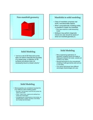
1. 3D modeling systems,
lecture topics:
• terminology used in examining and
comparing systems
• applying geometric modeling (especially
solids) to engineering design
• introduction to solid concepts
3D models create analogous
representations of an object.
• Analogous implies similar, but different.
• Therefore, 3D models are very similar to
the “real world” objects they are
representing but not necessarily identical.
Model is an approximation of
real object.
• Term for the “quality of approximation”
is faithfulness.
• Faithful model incorporates those
attributes necessary to the design or to
the analysis being performed.
• A model need not include all physical
real world features to be “faithful”
Model database
• As previously noted, the heart of a
geometric model is the model database.
• The database can be considered as an
organized form of the information which
describes the model.
• Database information for solids divided
into two general categories, geometric
and topological.
Geometry
• Geometric data relates to dimensional
information, e.g.
– the location of points in space
– the shape and size of geometric features.
Topology
• Topology: refers to the connectivity of
the elements which make up the model,
e.g.
– two faces intersect at an edge
• Inclusion of topological data makes
solid models computationally verifiable.
2. Two objects with the same
topology but different
geometry.
Data format
• model data may be stored:
– explicitly (evaluated data)
• Complete mathematical entity definitions are
stored in the database
– or implicitly (unevaluated data)
• Definitions not stored, but rather computed as
needed
• For example, the curve defined by intersection
of two surfaces or…
• an edge computed for display, then discarded
when not needed (recomputed at next display)
Data / Format
• In practice, database not strictly
evaluated or unevaluated but some
combination
Primary vs. Secondary models
• Systems typically maintain multiple data
representations
• The data used by fundamental modeling
operations is the primary model
• Other representations (which may or
may not be solid) are referred to as
secondary models
Secondary models
• Secondary models derived from primary
model for use is specific applications:
– display, analysis (FEA), manufacturing,
documentation (drawings), data exchange
• Secondary models are maintained to
reduce regeneration times when models
are required.
• Some modelers maintain a log of steps
performed. This log may be considered
a secondary model.
Associativity
• One form of associativity is the direct
connection of primary to secondary
models.
• Associativity can permit alteration of
one model when another is modified
– e.g. “top-down” associativity: alter primary,
secondary documentation file changes
3. Associativity
• An example of this would be the update
of display information when a change to
model geometry is made.
• This concept (associativity) also
appears in the relationship between
parent and child geometry and in the
extraction of mechanical drawings from
a solid model.
Model evaluation factors:
• domain and expressive power
• uniqueness
• validity.
Domain and Expressive
power
• domain refers to the range of model
geometries which may be generated by
a particular modeler.
• some modeling system supply the user
with broader domain
• expressive power: is the primary model
exact or approximate representation?
Uniqueness
• Concept of singularity between model
and database
• Two types of uniqueness may be
considered.
– Interpretation: Can the database represent
more than one object.
– Expression: Can more than one database
represent the same object?
Validity
• whether or not the model represents an
object which can exist in the real world.
• many solid modeling systems include
checks of model validity in their
architecture.
• validity checks often involve topological
checks
Manifold vs.
Non-manifold geometry
• Mathematically manifold geometry
means every point on a surface has
“neighborhood” (infinitesimal sphere)
around it that can be deformed onto a
locally planar surface.
• More simply: manifold geometry rules
out objects which are not physically
realizable such as those with features
joined along a single edge or vertex.
4. Non-manifold geometry Manifolds in solid modeling
• Class of manifolds comprises real
world, manufacturable objects.
• When computationally modeling solids,
is possible to create non-manifolds.
– One case would be a self-intersecting
model.
• Software may perform diagnostic
checks but user should be aware of
what non-manifold geometry is.
Solid Modeling
• “Just as a set of 2D lines and curves
does not need to describe the boundary
of a closed area, a collection of 3D
surfaces and planes does not
necessarily bound a closed volume.”
Solid Modeling
– Many engineering applications of
geometric modeling require the ability to
distinguish between the inside, outside and
surface of an object.
– Several techniques for the computerized
modeling of solid geometries exist and are
in use today.
– The various techniques have different
advantages disadvantages and uses.
Solid Modeling
• What properties are considered important for
of an effective solid modeling system
– Bounded - the boundary must limit and contain the
interior of the solid.
– Finite - Finite in size, model can be defined by a
limited set of information
– Homogeneously 3-dimensional or more simply, no
dangling faces or edges, boundary must always
be in contact with the interior