This patent document describes a method and apparatus for vacuum die casting. It involves using a two-part hood or enclosure that surrounds the die members. The hood is evacuated prior to each casting operation to produce smooth, non-porous castings. The hood sections separate along the parting line between the die members. Passages allow coolant to circulate through the die members, and a manifold in the hood accommodates different inlet/outlet connections needed for different die member configurations.

![which are threaded through the top of the body in alignment with said
ports.
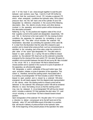
Each bore 107 and 108 has a hose conneetion at its outer end, that of
the bore 107 being slhownv at 115 in Fig. 6. The manifold is showin as
applied to the hood section 7 immediately to the rear of the flange
12. and one or more of the elbow fittings 112 of the manifold are
adapted to he connected with similar fittings of the underlying die
member througi-h loops :.f tubing designated 116 that are attached
livy unions to the fittins of the manifold and die member. Access to
the interior of the hood. for making the foregoing conneetions and for
other purposes. is had through one o-r me handl hole-. such as that
desiamited 11-. tie sae being shwv as liv'at- d n ilc top wall of thle
section 7. The}iiv i,le is c]os-d by a plate 119. sealed to, the
underlying wall 70 about the hand hole l, a aslket 120.
As previously mentioned, the cylinders 63, 70 and 75 are hneluded in a
pressure fluid systenm. desi.ayl hvlcraulie. In the cease of a
hydraulic system. there is the 75 usual tank from whi-ch the liquid is
drawn and to which it is ricuirnied. A pump.
usually operated by an electric motor, withdraws the liquid from the
tank and delivers it at the required pressure to the80 cylinders.
under the control of suitable valves. Since hy-draulic systems of this
sort are so well known it is regarded unnecessary to show the tank and
pump and the part of the system involving them. 85 The omission of
these parts simplifies considerably the dia'ra) of Fig. 10. This view
does include. hi xwever. hydraulic valves. preferably -l the spool
type. for controlling the adnii-ion of the liquid90 to the various
cylinders. adll the escape of the liquid thereArom Associated with the
respective cylinders 6t3 and 70 are valves 125 and 123. whlile two
v-alv-es, 127 and 128s. are assowit,1 with the cylindler 95 for a
reason that will] presently appear.
It may be explainedl at this point that relatively large sp,,l ralves
are used in conjunction with 1l, t lindlers 63 and 75.
because these lx ti are required to 100 handle liquid in eowisiderable
volume, this heinm indicated by ti, facet that. in practice, the
condfluits,a, pipes used therewith are in excess of,ie inch. Onl thle
other hand. a relativel- small spool valve is 105 used with the
eylinder 70. the pipes or conduits leading to and from the same being,
in practice. ltout one-half inch.
In the digranmmalea view of Fig. 10, however, relative sizes or
proportions are 110 ignored in favor of c]arity of illustration.
Beeause of the size ctf the valves 125, 127 and 128 an apprecill l,
molunt of power is required to shift tile spools thereof.
For this puirp,:,e I:aploay a pressure 115s fluid system. preferab l
pneumatic. Such system inhvolves, e-ide- a motor driven air pump or](https://image.slidesharecdn.com/zmkzfct9rwwqifsbo8kl-signature-04a9b2118fd45631bc78c881ec932a3e09a8557a2c01c89890c690eff6d9bb6f-poli-151225202706/85/780126-7-320.jpg)
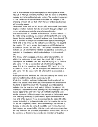
![and the die cavity closed, as il1nmlrited in Fig. 9.
Situated inii the ptju1 of the cam 156 is a so-called "die el-ed"
limit switch 185.70 This switch is bi;a-ecl to open position, and is
closed by szild -;iun when the piston 76 reaches the ritirh hand end
of its stroke. as abeoe explained. The switch is in a circiit 1-6 that
divides into75 four branches PS. 189, 190 and 191. The first of these
hraimhes, 188. includes a circuit closer 19:3 i id a solenoid 195.
associated with the previously mentioned pilot valve 130. Said pilbt
valv-e is biasedO80 to a position wherelin it directs compressed air
to Th, lower end of the hydrauLlic valve 12-, thereby to position the
spool of the litter valve so as to direct pressute fluid to the
bottom85 of the eylindlr 63 and lift the piston 62 thereiin.i thereby
effecting retraction of the clarging piston 58. However, when the
svlenod 195 is energized, these conclitions will be reversed and the o
pressure fluid will lie directed to the top of the cylinder 63 thereby
to depress the piston 62 and proje,-t lthe charging piston 58 toward
the hottim of the chargingcylinder 52, resulting in molten material0s
being displaced tihrouglh the gooseneek 54, nozzle 55 into the spae
between the die members.
The branch cir:uit 189 includes an electromagnetic me lnS or solenoid
196,100 that is operatively;a soeiated with the circuit closer 176. VA
ordingly, energization of this solenoid results in opening the circuit
167 and its branches 180 and 181. The branch cirenit 190 includes
anjos electric timer 197, that is operatively connected to the two
previously mentioned circuit closers 170 and 193 and functions, after
a relatively brief interval of time for which the instrument is set,
110 to open the circuit 166. with its branches 171 and 172. and the
circuit 188. In the branch circuit 191 is an electric timer 198 that
has operative connectionll with the circuit closer 152 in the circuit
150.115 Accordingly, a given interval of time after this final circuit
191 is energized, the circuit 150. thirolh which a cycle of operation
is initited, and all other circuits eontrolied ly the starting switch
120 146, will be opened thereby to conclude the cycle.
With the eharame.,nd performance of the control s-ystem in miind, the
operation of the apparatuin y -e revieweld)riefly 125 as ollows: The
p:r irtus is placed in operative condh-,. closing the main switch
1:37. Th!],_ ltishes communication between the uit pump 96 and the
tank 85, it being assumed that the motor 130 780,126 780,126 97 is
energized at al] times the die casting apparatus is in operation. A
cycle is started by momentarily depressing the button 146. The circuit
closed by the starting switch is locked in by the action of solenoid
149 and switch 148, as previously explained. Henceforth, the cycle
progresses automatically. The movable die member is advanced toward
the stationary die member 24 and is stopped with the die members](https://image.slidesharecdn.com/zmkzfct9rwwqifsbo8kl-signature-04a9b2118fd45631bc78c881ec932a3e09a8557a2c01c89890c690eff6d9bb6f-poli-151225202706/85/780126-11-320.jpg)