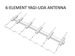
6 element yagi-uda antenna
•Download as PPTX, PDF•
1 like•1,301 views

UHF ANTENNA DESIGN
Report
Share
Report
Share

Recommended
Attenuators and phase shifters 24
This document discusses attenuators and phase shifters. It describes how attenuators are used to reduce signal power without distortion, and includes fixed and variable types. Fixed attenuators are commonly used where a fixed amount of power is needed, while variable attenuators provide continuous or stepwise adjustable attenuation using methods like flap or vane designs. Phase shifters are also discussed, including ferrite and semiconductor types. Applications of phase shifters include communication systems, radar, and industrial uses. Key specifications for digital phase shifters are provided.
Parameters of multipath channel
Naveen Kumar's document discusses small-scale fading in mobile wireless channels. It describes the effects of multipath propagation, Doppler shifts from mobility, and how these cause rapid fluctuations in signal strength over small distances and time periods. It also defines several key parameters that characterize mobile multipath channels, including coherence bandwidth, Doppler spread, coherence time, delay spread, and excess delay spread. These parameters quantify the time-dispersive and time-varying nature of wireless channels.
Optical fiber
Optical fibers experience various intrinsic and extrinsic losses that limit signal strength over long distances. Intrinsic losses include material absorption and scattering due to fiber imperfections. Absorption is caused by molecular vibrations and impurities, while scattering results from refractive index fluctuations. Extrinsic losses include bending, launching, and connector losses. Bending losses occur from macroscopic or microscopic bends, launching losses are from imperfect coupling into the fiber, and connector losses are due to core misalignments between joined fibers. Together these losses contribute to the overall attenuation of signals transmitted through optical fibers.
Ssb generation method
The document discusses three main methods for generating single-sideband suppressed carrier (SSB-SC) signals: the filter method, phase shift method, and Weaver method. The filter method uses a balanced modulator followed by a filter to remove the unwanted sideband. The phase shift method uses two balanced modulators with one audio input phase shifted 90 degrees. The Weaver method uses four balanced modulators, two audio filters, and two 90 degree phase shifters to generate the SSB signal without a filter or complex phase shifter.
Digital Communication 4
This document discusses bandwidth utilization and multiplexing techniques. It begins by explaining that bandwidth is a precious commodity in communication and that bandwidth utilization aims to make wise use of available bandwidth. It then discusses various multiplexing techniques including frequency-division multiplexing (FDM), time-division multiplexing (TDM), and wavelength-division multiplexing (WDM). For each technique, it provides examples and applications. It also covers digital carrier systems like T1, T2, T3 and discusses the North American digital multiplexing hierarchy.
Array antennas
The document discusses different types of antenna arrays, including broadside arrays, end-fire arrays, and binomial arrays. A broadside array consists of half-wave dipoles spaced by half wavelengths that produces a highly directional radiation pattern perpendicular to the array. An end-fire array uses two half-wave dipoles spaced by half a wavelength and radiates in the plane of the dipoles. A binomial array arranges radiating sources according to binomial coefficients to reduce side lobes and optimize directivity.
Optical Fiber Communication Part 3 Optical Digital Receiver
Current generated by photodetector is very weak and is adversely effected by random noises associated with photo detection process. When amplified, this signal further gets corrupted by amplifiers. Noise considerations are thus important in designing optical receivers.
Most meaningful criteria for measuring performance of a digital communication system is average error probability, and in analog system, it is peak signal to rms noise ratio. ...
YAGI UDA Antenna
The document discusses the Yagi-Uda antenna, which consists of multiple parallel dipole elements including a reflector, driven element, and multiple directors. It operates in the HF to UHF bands and provides a directional radiation pattern with moderate gain. Key advantages are its directionality and ability to operate at high frequencies. Common applications include television reception and radar systems where its directional properties and moderate gain are beneficial.
Plasma ANTENNA ppt
This document discusses plasma antennas as an alternative to traditional antennas. Plasma antennas employ ionized gas or solid-state plasma as a conductive medium to transmit and receive electromagnetic signals. They have advantages over traditional antennas such as being smaller, lighter, more compact, and able to transmit signals at higher frequencies. However, plasma antennas also have higher power consumption and stability issues. Potential applications of plasma antennas include military communications, electronic warfare, wireless internet, and space communications due to their unique properties.
[Year 2012-13] Mimo technology
MIMO systems use multiple antennas at both the transmitter and receiver to improve wireless communication performance. By utilizing spatial diversity and spatial multiplexing, MIMO can increase data rates and spectral efficiency without additional bandwidth or power. It also provides diversity gain to combat fading and improve quality of service. Key techniques of MIMO include spatial multiplexing to increase capacity through multiple parallel data streams, and spatial diversity to improve signal quality through redundant transmission paths. MIMO systems show promise to achieve high data rates over wireless channels and help meet the growing demand for wireless network performance.
Receivers
Radio receivers pick up desired signals, reject unwanted signals, and demodulate carrier signals to recover original modulating signals. They intercept incoming modulated signals, select desired signals while rejecting others, amplify the selected RF signal, detect the modulated signal, amplify the modulating frequency signal. Receivers can be classified based on the application (AM, FM, communication, television, radar) or design (tuned radio frequency (TRF), super-heterodyne). The super-heterodyne receiver overcomes limitations of TRF receivers by downconverting RF signals to a lower intermediate frequency, allowing for better stability, selectivity and consistent bandwidth over frequency ranges.
Bpsk ppt
Binary phase shift keying (BPSK) is a digital modulation scheme that encodes data by changing the phase of carrier waves. BPSK uses two phases that are separated by 180 degrees, where one phase encodes a binary 1 and the other phase encodes a binary 0. It is a common modulation scheme used in wireless communications and other applications where data must be transmitted over a band-limited channel.
Yagi Uda Antenna
The Yagi-Uda antenna consists of a driven element connected to a transmission line and one or more passive parasitic elements. The reflector element is longer than the driven element to make it inductive, while the director elements are shorter than the driven element to make them capacitive. Together the elements produce a unidirectional beam with moderate directivity and gains of around 8dB. Adding more director elements increases the directivity. It has advantages of simple construction, low cost, and ease of feeding but has limitations of limited bandwidth and requiring additional elements for higher gains over longer distances.
Microstrip TL 1st 3
Microstrip transmission lines are used extensively in microwave integrated circuits. They consist of a conducting strip separated from a ground plane by a dielectric substrate and support a quasi-TEM wave. Microstrip lines can be easily fabricated using printed circuit board technology. Their characteristic impedance depends on the strip width, thickness, distance to the ground plane, and dielectric constant of the substrate material. Microstrip lines are used for interconnecting high-speed circuits due to their uniform signal paths and ability to be fabricated automatically, though they have higher radiation losses than other transmission line types.
EC6602-Antenna fundamentals new
This document provides an overview of electromagnetic radiation, antenna fundamentals, and wave propagation. It discusses antennas as the linkage between circuits and electromagnetic fields. Key concepts covered include the electromagnetic spectrum, frequency-wavelength relationships, antenna radiation patterns, gain, directivity, polarization, and near, intermediate, and far field regions. Common antenna types for mobile communication like dipoles, monopoles, and arrays are also mentioned. Baluns are described as devices that convert between balanced and unbalanced signals.
MicroStrip Antenna
MicroStrip Antenna
Introduction .
Micro-Strip Antennas Types .
Micro-Strip Antennas Shapes .
Types of Substrates (Dielectric Media) .
Comparison of various types of flat profile printed antennas .
Advantages & DisAdvantages of MSAs .
Applications of MSAs .
Radiation patterns of MSAs .
How to Optimizing the Substrate Properties for Increased Bandwidth ?
Comparing the different feed techniques .
Frequency translation
In this ppt we learn about the method of frquency translation.How it can be done , what are their benefits etc.
Antenna Basics
By completing this presentation will be have a clear idea about Antenna's working principles, Antenna's Types & Antenna's Parameters. At the end to this document you'll have a brief idea about Antenna's Tilt vs Distance Calculation & Cluster wise optimum Antenna Selection procedure. Impact of antenna PIM & VSWR have been described elaborately in this document as well.
Microstrip Patch Antenna Design
Design & Study of Microstrip Patch Antenna.The project here provides a detailed study of how to design a probe-fed Square Micro-strip Patch Antenna using HFSS, v11.0 software and study the effect of antenna dimensions Length (L), and substrate parameters relative Dielectric constant (εr), substrate thickness (t) on the Radiation parameters of Bandwidth and Beam-width.
M ary psk and m ary qam ppt
M-ary encoding allows for digital signals with multiple possible conditions or voltage levels through the use of multiple binary variables. The number of conditions possible is represented by M, while the number of bits needed to produce those conditions is given by the logarithmic relationship N = log2M. M-ary PSK and M-ary QAM are two common types of M-ary encoding. M-ary PSK varies the phase of a carrier signal, while M-ary QAM varies both the amplitude and phase, allowing for greater power efficiency but identical bandwidth efficiency as M-ary PSK. Both modulation schemes use a constellation diagram to represent the multiple symbol states.
Multiple Access Techniques
Multiple Access Techniques:
Pre-assigned FDMA,
Demand-assigned FDMA,
Spade System,
TDMA,
Frame and burst formats of TDMA,
Reference burst,
On-board signal processing,
Network Synchronization,
Satellite-Switched TDMA
Antennas and Wave Propagation
1. The document discusses various topics related to antenna parameters and radiation patterns. It describes the radiation mechanism of single wire, two wire, and dipole antennas.
2. Current distribution on thin wire antennas is explained. Parameters like radiation patterns, patterns in principal planes, main lobe and side lobes, beam widths, and polarization are discussed.
3. Key points about radiation patterns, coordinate systems, principal plane patterns, and definitions of main lobe, side lobes, half power beamwidth and first null beamwidth are provided.
Dipole Antenna
A dipole antenna is the simplest antenna but its radiation characteristics are very good. The main drawback of a dipole antenna is very narrow bandwidth. The analysis of a dipole antenna can be performed with integration of Hertzian dipoles.
Gmsk
Gaussian Minimum Shift Keying (GMSK) is a form of continuous-phase frequency shift keying that uses a Gaussian filter to generate a constant envelope signal. It provides better spectral efficiency than MSK through bandwidth reduction while maintaining low intersymbol interference. GMSK is used widely in wireless technologies like GSM and CDPD due to its power efficiency and good bit error rate performance compared to other modulation schemes. While more spectrally efficient than MSK, GMSK also has slightly higher error rates and requires more complex receivers.
Dipole antenna
The document describes the design and simulation of a basic half-wave dipole antenna. Key points:
1) The aim is to design a dipole antenna for a given frequency of 3.3 GHz and study the effects of varying the dielectric constant and substrate thickness on the radiation properties and frequency response.
2) Important antenna characteristics to consider include radiation patterns, gain, and frequency response.
3) The half-wave dipole antenna is designed with each arm measuring 22.725mm to operate at the target frequency, and each arm width is 4.545mm.
4) Simulation shows the antenna operates at 2.8GHz with a return loss of -14.50dB and gain of
Antenna array
The document discusses concepts of antenna arrays and their applications. It provides an overview of antenna arrays, including their need, types, parameters that influence their radiation patterns, and applications. The key points are:
1) An antenna array consists of multiple antenna elements arranged to form a single antenna with controllable radiation patterns. This allows for increased directivity, narrower beams, and electronic beam steering.
2) Common array types include linear, circular, and planar arrays. Parameters like element spacing, excitation amplitudes and phases shape the overall radiation pattern.
3) Applications of antenna arrays include radar systems, wireless communications, and radio astronomy due to their ability to focus signals in desired directions without mechanical movement.
Antenna
This document describes different types of antennas used for transmitting and receiving electromagnetic waves. It discusses transmitter and receiver antennas. Specific antenna types covered include Yagi-Uda antennas, log-periodic antennas, helix antennas, parabolic antennas, loop antennas, and antenna arrays. Each antenna type has distinct characteristics that make it suitable for different frequency ranges and applications.
More Related Content
What's hot
Plasma ANTENNA ppt
This document discusses plasma antennas as an alternative to traditional antennas. Plasma antennas employ ionized gas or solid-state plasma as a conductive medium to transmit and receive electromagnetic signals. They have advantages over traditional antennas such as being smaller, lighter, more compact, and able to transmit signals at higher frequencies. However, plasma antennas also have higher power consumption and stability issues. Potential applications of plasma antennas include military communications, electronic warfare, wireless internet, and space communications due to their unique properties.
[Year 2012-13] Mimo technology
MIMO systems use multiple antennas at both the transmitter and receiver to improve wireless communication performance. By utilizing spatial diversity and spatial multiplexing, MIMO can increase data rates and spectral efficiency without additional bandwidth or power. It also provides diversity gain to combat fading and improve quality of service. Key techniques of MIMO include spatial multiplexing to increase capacity through multiple parallel data streams, and spatial diversity to improve signal quality through redundant transmission paths. MIMO systems show promise to achieve high data rates over wireless channels and help meet the growing demand for wireless network performance.
Receivers
Radio receivers pick up desired signals, reject unwanted signals, and demodulate carrier signals to recover original modulating signals. They intercept incoming modulated signals, select desired signals while rejecting others, amplify the selected RF signal, detect the modulated signal, amplify the modulating frequency signal. Receivers can be classified based on the application (AM, FM, communication, television, radar) or design (tuned radio frequency (TRF), super-heterodyne). The super-heterodyne receiver overcomes limitations of TRF receivers by downconverting RF signals to a lower intermediate frequency, allowing for better stability, selectivity and consistent bandwidth over frequency ranges.
Bpsk ppt
Binary phase shift keying (BPSK) is a digital modulation scheme that encodes data by changing the phase of carrier waves. BPSK uses two phases that are separated by 180 degrees, where one phase encodes a binary 1 and the other phase encodes a binary 0. It is a common modulation scheme used in wireless communications and other applications where data must be transmitted over a band-limited channel.
Yagi Uda Antenna
The Yagi-Uda antenna consists of a driven element connected to a transmission line and one or more passive parasitic elements. The reflector element is longer than the driven element to make it inductive, while the director elements are shorter than the driven element to make them capacitive. Together the elements produce a unidirectional beam with moderate directivity and gains of around 8dB. Adding more director elements increases the directivity. It has advantages of simple construction, low cost, and ease of feeding but has limitations of limited bandwidth and requiring additional elements for higher gains over longer distances.
Microstrip TL 1st 3
Microstrip transmission lines are used extensively in microwave integrated circuits. They consist of a conducting strip separated from a ground plane by a dielectric substrate and support a quasi-TEM wave. Microstrip lines can be easily fabricated using printed circuit board technology. Their characteristic impedance depends on the strip width, thickness, distance to the ground plane, and dielectric constant of the substrate material. Microstrip lines are used for interconnecting high-speed circuits due to their uniform signal paths and ability to be fabricated automatically, though they have higher radiation losses than other transmission line types.
EC6602-Antenna fundamentals new
This document provides an overview of electromagnetic radiation, antenna fundamentals, and wave propagation. It discusses antennas as the linkage between circuits and electromagnetic fields. Key concepts covered include the electromagnetic spectrum, frequency-wavelength relationships, antenna radiation patterns, gain, directivity, polarization, and near, intermediate, and far field regions. Common antenna types for mobile communication like dipoles, monopoles, and arrays are also mentioned. Baluns are described as devices that convert between balanced and unbalanced signals.
MicroStrip Antenna
MicroStrip Antenna
Introduction .
Micro-Strip Antennas Types .
Micro-Strip Antennas Shapes .
Types of Substrates (Dielectric Media) .
Comparison of various types of flat profile printed antennas .
Advantages & DisAdvantages of MSAs .
Applications of MSAs .
Radiation patterns of MSAs .
How to Optimizing the Substrate Properties for Increased Bandwidth ?
Comparing the different feed techniques .
Frequency translation
In this ppt we learn about the method of frquency translation.How it can be done , what are their benefits etc.
Antenna Basics
By completing this presentation will be have a clear idea about Antenna's working principles, Antenna's Types & Antenna's Parameters. At the end to this document you'll have a brief idea about Antenna's Tilt vs Distance Calculation & Cluster wise optimum Antenna Selection procedure. Impact of antenna PIM & VSWR have been described elaborately in this document as well.
Microstrip Patch Antenna Design
Design & Study of Microstrip Patch Antenna.The project here provides a detailed study of how to design a probe-fed Square Micro-strip Patch Antenna using HFSS, v11.0 software and study the effect of antenna dimensions Length (L), and substrate parameters relative Dielectric constant (εr), substrate thickness (t) on the Radiation parameters of Bandwidth and Beam-width.
M ary psk and m ary qam ppt
M-ary encoding allows for digital signals with multiple possible conditions or voltage levels through the use of multiple binary variables. The number of conditions possible is represented by M, while the number of bits needed to produce those conditions is given by the logarithmic relationship N = log2M. M-ary PSK and M-ary QAM are two common types of M-ary encoding. M-ary PSK varies the phase of a carrier signal, while M-ary QAM varies both the amplitude and phase, allowing for greater power efficiency but identical bandwidth efficiency as M-ary PSK. Both modulation schemes use a constellation diagram to represent the multiple symbol states.
Multiple Access Techniques
Multiple Access Techniques:
Pre-assigned FDMA,
Demand-assigned FDMA,
Spade System,
TDMA,
Frame and burst formats of TDMA,
Reference burst,
On-board signal processing,
Network Synchronization,
Satellite-Switched TDMA
Antennas and Wave Propagation
1. The document discusses various topics related to antenna parameters and radiation patterns. It describes the radiation mechanism of single wire, two wire, and dipole antennas.
2. Current distribution on thin wire antennas is explained. Parameters like radiation patterns, patterns in principal planes, main lobe and side lobes, beam widths, and polarization are discussed.
3. Key points about radiation patterns, coordinate systems, principal plane patterns, and definitions of main lobe, side lobes, half power beamwidth and first null beamwidth are provided.
Dipole Antenna
A dipole antenna is the simplest antenna but its radiation characteristics are very good. The main drawback of a dipole antenna is very narrow bandwidth. The analysis of a dipole antenna can be performed with integration of Hertzian dipoles.
Gmsk
Gaussian Minimum Shift Keying (GMSK) is a form of continuous-phase frequency shift keying that uses a Gaussian filter to generate a constant envelope signal. It provides better spectral efficiency than MSK through bandwidth reduction while maintaining low intersymbol interference. GMSK is used widely in wireless technologies like GSM and CDPD due to its power efficiency and good bit error rate performance compared to other modulation schemes. While more spectrally efficient than MSK, GMSK also has slightly higher error rates and requires more complex receivers.
Dipole antenna
The document describes the design and simulation of a basic half-wave dipole antenna. Key points:
1) The aim is to design a dipole antenna for a given frequency of 3.3 GHz and study the effects of varying the dielectric constant and substrate thickness on the radiation properties and frequency response.
2) Important antenna characteristics to consider include radiation patterns, gain, and frequency response.
3) The half-wave dipole antenna is designed with each arm measuring 22.725mm to operate at the target frequency, and each arm width is 4.545mm.
4) Simulation shows the antenna operates at 2.8GHz with a return loss of -14.50dB and gain of
Antenna array
The document discusses concepts of antenna arrays and their applications. It provides an overview of antenna arrays, including their need, types, parameters that influence their radiation patterns, and applications. The key points are:
1) An antenna array consists of multiple antenna elements arranged to form a single antenna with controllable radiation patterns. This allows for increased directivity, narrower beams, and electronic beam steering.
2) Common array types include linear, circular, and planar arrays. Parameters like element spacing, excitation amplitudes and phases shape the overall radiation pattern.
3) Applications of antenna arrays include radar systems, wireless communications, and radio astronomy due to their ability to focus signals in desired directions without mechanical movement.
Antenna
This document describes different types of antennas used for transmitting and receiving electromagnetic waves. It discusses transmitter and receiver antennas. Specific antenna types covered include Yagi-Uda antennas, log-periodic antennas, helix antennas, parabolic antennas, loop antennas, and antenna arrays. Each antenna type has distinct characteristics that make it suitable for different frequency ranges and applications.
What's hot (20)
Demodulation of fm slope and balanced slope detector
Demodulation of fm slope and balanced slope detector