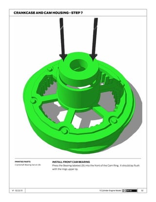
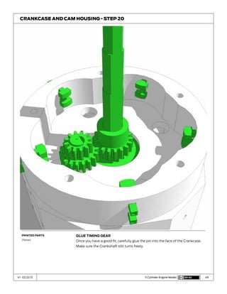
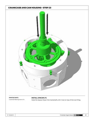
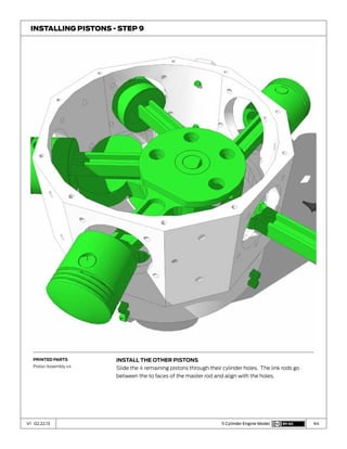
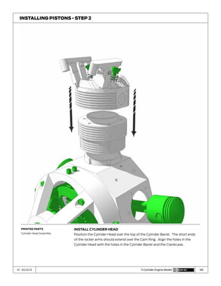
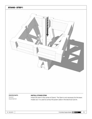
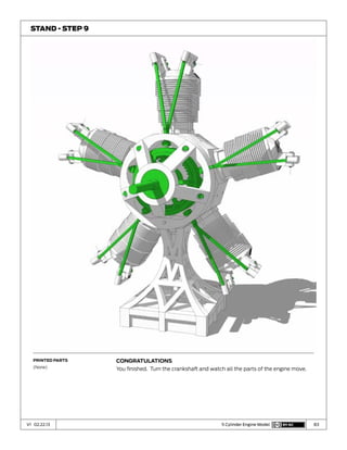
The document provides assembly instructions for building a 5 cylinder radial engine model from 3D printed parts. It begins with an inventory of the 260+ printed parts needed and their print settings. It then outlines the step-by-step assembly process for the cylinders, cylinder heads, crankcase and cam housing. The instructions include pressing bearings and pins into place and ensuring moving parts fit freely. Proper positioning of parts is emphasized to ensure correct assembly.
Blending of traditional hot forging practice with the latest technologies in computational simulation,sensing and closed loop controls,to improve process efficiency.
There are 8 types of moulding sand that I have explained in this PPT.
Moulding sand types such as green sand, dry sand, parting sand, loam sand, facing sand, backing sand, core sand and system sand.
The document provides instructions for visually inspecting and servicing disc brake calipers. It describes how to disassemble a caliper, check components for wear, clean and lubricate parts, and reassemble the caliper. Key steps include removing the caliper, inspecting pads and pistons, cleaning the caliper bore, replacing seals, lubricating with brake fluid, and reinstalling the caliper. Common issues like worn caliper mounts and stuck pistons are also discussed.
The document summarizes different types of clutch friction materials and components. It describes organic, heavy duty, semi-metallic, and copper ceramic discs, as well as carbon-carbon materials. It also discusses diaphragm style pressure plates, clutch release bearings and forks, and linkage, cable, and hydraulic clutch release mechanisms.
The document discusses the manufacturing process of engine components. It describes the steps as:
1. Casting of the engine block using conventional or expendable patterns. Other components like cylinder heads, crankshafts and connecting rods are also cast or forged.
2. The castings undergo machining and heat treatment processes. Pistons are manufactured through gravity casting, squeeze casting, and then machined.
3. Valves are upset forged and heat treated to improve strength and wear resistance. Cylinder liners and piston rings are also manufactured to complete the engine assembly.
The document provides information on the front and rear axle systems for LCV vehicles. It discusses the objectives, agenda, and general information about the front axle 709/909 type. The document outlines the process for overhauling the front axle, including removal from the vehicle, inspection, and removal and assembly of wheel hub and stub axle components. It also discusses technical specifications, adjustments and settings for the front axle. For the rear axle, it provides information on the 407/709 type including removal, disassembly, inspection and reassembly processes.
The document discusses the components and functions of a crankshaft. It lists the group members and defines a crankshaft as a shaft that transmits power from the engine and converts the reciprocating motion of the piston into rotational motion. It describes the main parts of the crankshaft including the throws, journals, webs, counterweights, big end bearings and main bearings. It explains that counterweights are needed to balance the crankshaft and prevent vibrations from damaging the engine.
This document discusses idlers and pulleys used in conveyor systems. It describes different types of idlers like carry idlers and return idlers, and their purposes in shaping the belt load and supporting the belt. It discusses CEMA classifications for idlers and common idler diameters. It also describes factors involved in selecting idlers like idler load, belt tension, and misalignment load. For pulleys, it discusses types like drum and wing pulleys and their purpose in transmitting power and changing belt direction. It covers CEMA duty classifications and describes pulley lagging used to increase traction. The document concludes with discussing belt tensions at different locations and how to select pulley diameter based on wrap angle and belt tension.
The Classification of Rubber Calenders is based on (1) The Number of rolls, and (2) The Position or Orientation of the rolls. Here is a quick info-sheet to help you grasp the different rubber calenders quickly.
The engine block is a critical component that houses the internal parts of an engine. It is typically made of cast iron or aluminum alloys due to their ability to withstand high stresses and temperatures. The manufacturing process involves pattern making, casting, and machining. Patterns are used to create molds for casting the block. The block is then machined to final specifications. Proper material selection and manufacturing processes are needed to produce an engine block that can withstand combustion pressures and temperatures for the life of the vehicle.
Bearings are used to support rotating shafts and come in different types depending on whether they are designed to withstand axial thrusts, radial loads, or both. The main bearing types are ball bearings, which use spheres, and cylindrical roller bearings, which use cylinders, with each type having different capacities for loads and misalignment. Deep groove ball bearings can withstand both radial and axial loads, while angular contact ball bearings have increased axial load capacity and self-aligning ball bearings are very tolerant of misalignment.
This document provides an overview of forging and press working processes. It defines forging as plastically deforming metal at elevated temperatures using compressive forces. The document classifies forging methods as open die, closed die, drop, hammer, and press forging based on the process and equipment used. It also defines press working and classifies press types and operations including cutting operations like blanking and punching, and forming operations like bending and drawing. Key tools for forging like hammers, tongs, and dies are also introduced.
The document discusses that there are two kinds of people in the world and prompts the reader to identify which one they are. It then provides suggestions for using this idea in a classroom setting by showing evocative picture prompts to trigger discussion among students about which category they fall into. Contact information is given for further questions.
This document discusses various components and classifications of vehicle suspension systems. It describes common suspension links like control arms, radius rods, and trailing arms. It explains suspension types such as double wishbone, MacPherson strut, swing axle, live axle with leaf springs, and de Dion tube suspensions. It also covers rear suspension configurations including live-axle with coil springs and independent rear suspension with shocks. In summary, the document provides an overview of key suspension links and classifications of front and rear suspension designs used in automobiles.
Cams are devices that convert rotary, oscillating, or linear motion into reciprocating or linear motion and come in various types including plate, cylindrical, face, and end cams. Common cam followers include wedge, roller, and flat ended followers. The motion profile of the cam determines the motion of the follower and includes profiles like uniform velocity, uniform acceleration/retardation, and simple harmonic motion.
Pistons, rings, and connecting rods are essential components that transfer force between the combustion chamber and crankshaft. Pistons seal the combustion chamber and are attached to connecting rods. Pistons are constructed of cast or forged aluminum alloys and operate at high speeds, transferring force twice per crankshaft revolution. Piston rings include compression rings that seal the combustion chamber from the cylinder wall and an oil control ring that separates oil from the combustion gases. Proper piston, ring, and connecting rod assembly and maintenance are critical for engine performance and efficiency.
The document discusses different types of flow that can occur when discharging bulk solids from storage bins. Funnel flow occurs when only the material near the outlet flows, leaving stagnant zones near the walls that are discharged last. Mass flow is ideal, occurring when the entire contents of the bin are in motion during discharge, resulting in first-in, first-out flow and a uniform discharge rate. Design factors like bin geometry, outlet size and shape, and material properties determine whether mass or funnel flow occurs. The key advantages of mass flow are a consistent discharge rate and the ability to fully empty the bin.
Kubota d1005 e3 bg diesel engine service repair manualfusjjfksekmme
This document provides specifications for KUBOTA 05-E3B and 05-E3BG series diesel engines, including dimensions, displacement, power output, engine speed, injection timing, and other technical details. It lists specifications for multiple engine models, noting variations in items like number of cylinders, bore size, power ratings, and dimensions. The specifications provided are for standard engines of each base model. Conversions from kilowatts to horsepower are given.
The document discusses the requirements and components of a clutch mechanism. It provides details on:
1. The key requirements of a clutch include transmitting maximum engine torque without slippage, dissipating large amounts of heat generated, engaging gradually without jerks, being dynamically balanced, damping vibrations, having minimum inertia when disengaged, and requiring minimal force to disengage.
2. The main components of a clutch are the clutch plate, friction facings, pressure plate, springs, throwout bearing, and release levers. The clutch plate transfers torque via friction facings attached to its steel plate. The pressure plate applies pressure to the clutch plate via springs.
3. Different types of clutches include single
The document discusses piston manufacturing processes and materials. It describes how pistons transform thermal energy from combustion into rotational motion. Various piston head and skirt designs are presented. Pistons can be made of aluminum via casting or forging, with different properties for each. Piston rings are often made of heat-treated nodular cast iron, chromium steel, or molybdenum alloys to provide durability and reduce wear and scuffing. Cylinder liners are centrifugally cast from materials like iron and aluminum alloys to form the inner cylinder surface with properties like wear resistance.
The document summarizes various types of machinery used for crushing and grinding materials. It describes jaw crushers, gyratory crushers, hammer mills, roller mills, ball mills, and other equipment. The key components and operating principles of each type are explained, including how they employ compressive, impact, or shear forces to reduce the size of materials.
This document discusses different types of clutches. It begins by defining a clutch as a mechanical device that connects and disconnects two rotating shafts to transmit or disengage power. It then describes several types of clutches including disc clutches, cone clutches, centrifugal clutches, and positive contact clutches. The document also provides details on single plate and multi-plate clutch designs, materials, and operating principles. It explains how clutches transmit torque via friction between contacting surfaces.
This document summarizes the metal forming process of rolling. It describes how rolling works by passing metal between rolls, subjecting it to compressive and shear stresses. It discusses different types of rolling mills and explains how hot and cold rolling differ, with hot rolling reducing size at high temperatures and cold rolling providing better surface finish. The document also outlines defects that can occur during rolling such as surface irregularities, inclusions, and edge cracking or center splitting.
This document discusses sheet metal forming processes. It introduces various sheet metal forming methods like bending, stretching, deep drawing, and identifies common defects. The objectives are to describe sheet metal forming processes, discuss variables that affect formability, and emphasize defects and solutions. Various forming equipment, stresses involved, and classifications of sheet metal parts and processes are outlined over several pages.
1. The document provides design procedures and formulas for selecting various transmission system components from a design data book, including:
2. Procedures are given for designing flat belts, v-belts, chain drives, wire ropes, spur gears, and helical gears using steps that include selecting standard component sizes, calculating speeds and power ratings, and checking safety factors.
3. Formulas are drawn from the design data book to calculate values like belt speed and load rating, chain breaking load and bearing stress, wire rope bending load, and initial gear design torque. Standard values are then selected based on these calculations.
This document provides an overview of the Technician Level 2 Module 5 training program which focuses on brake and suspension systems for LCV vehicles. The objectives are to understand S-cam air brake systems, perform inspections and overhauls of brake components, and understand hydraulic brake and suspension systems. The agenda covers S-cam brakes, hydraulic brakes, park brakes, and suspension systems.
1. Общая характеристика и классификация соединительных тканей.Эмбриональный гистогенез.
2. Кровь. Компоненты крови. Химический состав плазмы крови.
3. Классификация форменных элементов крови. Гемограмма.
4. Эритроциты. Строение(форма, размеры в норме,при старении и патологических изменениях).Плазмолемма и премембранный цитоскелет эритроцитов.Ретикулоциты. Функции.
5. Лейкоциты. Классификация лейкоцитов. Лейкоцитарная формула.
6. Нейтрофильные гранулоциты. Световая и электронная микроскопия(строение
ядра, цитоплазмы, цитоплазматических гранул). Функции.
7. Эозинофильные гранулоциты. Световая и электронная микроскопия(строение
ядра, цитоплазмы, специфические и азурофильные гранулы). Функции.
8. Базофильные гранулоциты. Световая и электронная микроскопия(строение ядра, цитоплазмы, специфические и азурофильные гранулы). Функции.
9. Агранулоциты. Моноциты. Световая и электронная микроскопия(строение ядра и цитоплазмы). Роль в системе мононуклеарных фагоцитов.
10. Агранулоциты. Лимфоциты. Классификация по морфологическому и
функциональному признаку. Световая и электронная микроскопия.Функции.
11. Тромбоциты. Световая и электронная микроскопия (строение гиаломера и
грануломера). Функции.
12. Лимфа. Состав лимфы. Связь с кровью, понятие о рециркуляции лимфоцитов
This document appears to be a training report submitted by Raj Pareek to the Department of Mechanical Engineering at Dr. K.N. Modi University. It provides an overview of Raj's one month training at the National Bearing Company (NBC). The report includes details about NBC's manufacturing processes, departments, products, quality standards and international collaborations. It also discusses bearing types, designations, material composition and the heat treatment process. The objective of Raj's training was to learn engineering production methods and better understand the theoretical knowledge through practical observations.
Threats to mobile devices are more prevalent and increasing in scope and complexity. Users of mobile devices desire to take full advantage of the features
available on those devices, but many of the features provide convenience and capability but sacrifice security. This best practices guide outlines steps the users can take to better protect personal devices and information.
Driving Business Innovation: Latest Generative AI Advancements & Success StorySafe Software
Are you ready to revolutionize how you handle data? Join us for a webinar where we’ll bring you up to speed with the latest advancements in Generative AI technology and discover how leveraging FME with tools from giants like Google Gemini, Amazon, and Microsoft OpenAI can supercharge your workflow efficiency.
During the hour, we’ll take you through:
Guest Speaker Segment with Hannah Barrington: Dive into the world of dynamic real estate marketing with Hannah, the Marketing Manager at Workspace Group. Hear firsthand how their team generates engaging descriptions for thousands of office units by integrating diverse data sources—from PDF floorplans to web pages—using FME transformers, like OpenAIVisionConnector and AnthropicVisionConnector. This use case will show you how GenAI can streamline content creation for marketing across the board.
Ollama Use Case: Learn how Scenario Specialist Dmitri Bagh has utilized Ollama within FME to input data, create custom models, and enhance security protocols. This segment will include demos to illustrate the full capabilities of FME in AI-driven processes.
Custom AI Models: Discover how to leverage FME to build personalized AI models using your data. Whether it’s populating a model with local data for added security or integrating public AI tools, find out how FME facilitates a versatile and secure approach to AI.
We’ll wrap up with a live Q&A session where you can engage with our experts on your specific use cases, and learn more about optimizing your data workflows with AI.
This webinar is ideal for professionals seeking to harness the power of AI within their data management systems while ensuring high levels of customization and security. Whether you're a novice or an expert, gain actionable insights and strategies to elevate your data processes. Join us to see how FME and AI can revolutionize how you work with data!
UiPath Test Automation using UiPath Test Suite series, part 5DianaGray10
Welcome to UiPath Test Automation using UiPath Test Suite series part 5. In this session, we will cover CI/CD with devops.
Topics covered:
CI/CD with in UiPath
End-to-end overview of CI/CD pipeline with Azure devops
Speaker:
Lyndsey Byblow, Test Suite Sales Engineer @ UiPath, Inc.
“An Outlook of the Ongoing and Future Relationship between Blockchain Technologies and Process-aware Information Systems.” Invited talk at the joint workshop on Blockchain for Information Systems (BC4IS) and Blockchain for Trusted Data Sharing (B4TDS), co-located with with the 36th International Conference on Advanced Information Systems Engineering (CAiSE), 3 June 2024, Limassol, Cyprus.
Goodbye Windows 11: Make Way for Nitrux Linux 3.5.0!SOFTTECHHUB
As the digital landscape continually evolves, operating systems play a critical role in shaping user experiences and productivity. The launch of Nitrux Linux 3.5.0 marks a significant milestone, offering a robust alternative to traditional systems such as Windows 11. This article delves into the essence of Nitrux Linux 3.5.0, exploring its unique features, advantages, and how it stands as a compelling choice for both casual users and tech enthusiasts.
Infrastructure Challenges in Scaling RAG with Custom AI modelsZilliz
Building Retrieval-Augmented Generation (RAG) systems with open-source and custom AI models is a complex task. This talk explores the challenges in productionizing RAG systems, including retrieval performance, response synthesis, and evaluation. We’ll discuss how to leverage open-source models like text embeddings, language models, and custom fine-tuned models to enhance RAG performance. Additionally, we’ll cover how BentoML can help orchestrate and scale these AI components efficiently, ensuring seamless deployment and management of RAG systems in the cloud.
Cosa hanno in comune un mattoncino Lego e la backdoor XZ?Speck&Tech
ABSTRACT: A prima vista, un mattoncino Lego e la backdoor XZ potrebbero avere in comune il fatto di essere entrambi blocchi di costruzione, o dipendenze di progetti creativi e software. La realtà è che un mattoncino Lego e il caso della backdoor XZ hanno molto di più di tutto ciò in comune.
Partecipate alla presentazione per immergervi in una storia di interoperabilità, standard e formati aperti, per poi discutere del ruolo importante che i contributori hanno in una comunità open source sostenibile.
BIO: Sostenitrice del software libero e dei formati standard e aperti. È stata un membro attivo dei progetti Fedora e openSUSE e ha co-fondato l'Associazione LibreItalia dove è stata coinvolta in diversi eventi, migrazioni e formazione relativi a LibreOffice. In precedenza ha lavorato a migrazioni e corsi di formazione su LibreOffice per diverse amministrazioni pubbliche e privati. Da gennaio 2020 lavora in SUSE come Software Release Engineer per Uyuni e SUSE Manager e quando non segue la sua passione per i computer e per Geeko coltiva la sua curiosità per l'astronomia (da cui deriva il suo nickname deneb_alpha).
UiPath Test Automation using UiPath Test Suite series, part 6DianaGray10
Welcome to UiPath Test Automation using UiPath Test Suite series part 6. In this session, we will cover Test Automation with generative AI and Open AI.
UiPath Test Automation with generative AI and Open AI webinar offers an in-depth exploration of leveraging cutting-edge technologies for test automation within the UiPath platform. Attendees will delve into the integration of generative AI, a test automation solution, with Open AI advanced natural language processing capabilities.
Throughout the session, participants will discover how this synergy empowers testers to automate repetitive tasks, enhance testing accuracy, and expedite the software testing life cycle. Topics covered include the seamless integration process, practical use cases, and the benefits of harnessing AI-driven automation for UiPath testing initiatives. By attending this webinar, testers, and automation professionals can gain valuable insights into harnessing the power of AI to optimize their test automation workflows within the UiPath ecosystem, ultimately driving efficiency and quality in software development processes.
What will you get from this session?
1. Insights into integrating generative AI.
2. Understanding how this integration enhances test automation within the UiPath platform
3. Practical demonstrations
4. Exploration of real-world use cases illustrating the benefits of AI-driven test automation for UiPath
Topics covered:
What is generative AI
Test Automation with generative AI and Open AI.
UiPath integration with generative AI
Speaker:
Deepak Rai, Automation Practice Lead, Boundaryless Group and UiPath MVP
Communications Mining Series - Zero to Hero - Session 1DianaGray10
This session provides introduction to UiPath Communication Mining, importance and platform overview. You will acquire a good understand of the phases in Communication Mining as we go over the platform with you. Topics covered:
• Communication Mining Overview
• Why is it important?
• How can it help today’s business and the benefits
• Phases in Communication Mining
• Demo on Platform overview
• Q/A
Let's Integrate MuleSoft RPA, COMPOSER, APM with AWS IDP along with Slackshyamraj55
Discover the seamless integration of RPA (Robotic Process Automation), COMPOSER, and APM with AWS IDP enhanced with Slack notifications. Explore how these technologies converge to streamline workflows, optimize performance, and ensure secure access, all while leveraging the power of AWS IDP and real-time communication via Slack notifications.
Full-RAG: A modern architecture for hyper-personalizationZilliz
Mike Del Balso, CEO & Co-Founder at Tecton, presents "Full RAG," a novel approach to AI recommendation systems, aiming to push beyond the limitations of traditional models through a deep integration of contextual insights and real-time data, leveraging the Retrieval-Augmented Generation architecture. This talk will outline Full RAG's potential to significantly enhance personalization, address engineering challenges such as data management and model training, and introduce data enrichment with reranking as a key solution. Attendees will gain crucial insights into the importance of hyperpersonalization in AI, the capabilities of Full RAG for advanced personalization, and strategies for managing complex data integrations for deploying cutting-edge AI solutions.
Best 20 SEO Techniques To Improve Website Visibility In SERPPixlogix Infotech
Boost your website's visibility with proven SEO techniques! Our latest blog dives into essential strategies to enhance your online presence, increase traffic, and rank higher on search engines. From keyword optimization to quality content creation, learn how to make your site stand out in the crowded digital landscape. Discover actionable tips and expert insights to elevate your SEO game.
Unlock the Future of Search with MongoDB Atlas_ Vector Search Unleashed.pdfMalak Abu Hammad
Discover how MongoDB Atlas and vector search technology can revolutionize your application's search capabilities. This comprehensive presentation covers:
* What is Vector Search?
* Importance and benefits of vector search
* Practical use cases across various industries
* Step-by-step implementation guide
* Live demos with code snippets
* Enhancing LLM capabilities with vector search
* Best practices and optimization strategies
Perfect for developers, AI enthusiasts, and tech leaders. Learn how to leverage MongoDB Atlas to deliver highly relevant, context-aware search results, transforming your data retrieval process. Stay ahead in tech innovation and maximize the potential of your applications.
#MongoDB #VectorSearch #AI #SemanticSearch #TechInnovation #DataScience #LLM #MachineLearning #SearchTechnology
2. 2V1 02.22.13 5 Cylinder Engine Model
3 - Introduction
4 - Sources and License information
5 - Inventory of parts
11 - Building the Cylinders
18 - Building the Cylinder Heads
25 - Building the Crankcase and Cam housing
55 - Installing the pistons
66 - Installing the Cylinders
74 - The stand
84 - grease
Table of Contents
3. 3V1 02.22.13 5 Cylinder Engine Model
Welcome to the most ambitious mechanical 3D printing
project you have ever attempted.
The 5 Cylinder Radial Engine is made up of more than 260 printed parts.
Working continually with a single printer, you can expect to spend more than
two weeks printing and several more days assembling.
Since the first Radial Engine was built in 1901, the technology has been
synonymous with aviation. The first flight across the English Channel was
powered by a 3 cylinder 12 hp radial engine built by Italian engine designer
Alessandro Anzani. The heavy bombers of the Second World War were
powered by massive 28 cylinder 4,300 hp radial monsters built by Pratt &
Whitney. The basic operating principle illustrated by this model is accurate to
both. Radial engines have largely been supplanted in aviation by gas turbines,
but are still found today on specialized acrobatic aircraft.
This 5 Cylinder Radial Engine Model is based on the Forest Edwards Radial 5, a
radial model aircraft engine.
Notes
- Parts in these plans are represented in two colors, white and green. These
colors correspond to the colors used in my models. In general, green parts are
moving and attachment parts, while white parts are structural or case parts.
- PLA is a material that wears very quickly. During assembly, when you find
parts that are too snug, forcing them through their motions several times will
usually wear away enough excess material to ensure a good fit. After assembly,
it’s critical to use some kind of grease on the cam surfaces and timing gears to
keep them from wearing away.
-PTFE or Silicon grease should be used to lubricate the Engine
- Most parts of this model are designed to be attached with snap-pins.
- Some parts of the model need to be glued, and in some cases glue may
need to be used to supplement the strength of the snap-pins. When gluing,
remember to be patient and wait for the glue to fully dry. The last thing you
want is to accidentally get super glue all over the inner working of the model.
- I recommend gel style super glue, it’s less likely to drip and run.
- A small tack hammer, hobby knife and sandpaper will be extremely useful
during assembly.
Introduction
4. 4V1 02.22.13 5 Cylinder Engine Model
Source
This engine started from excellent paper plans drawn by Robert Sigler. The
engine described in Roberts’s plans is intended to be machined from metal, and
had to be extensively modified to work with desktop 3d printing technology.
Some pieces, like the cylinder barrels and cam ring, had to be subdivided into
printable sub-units. Other parts were re-designed or had their tolerances
altered in order to create a working mechanical model. Windows cut into the
cam ring and cam housing make the moving parts of the cam system visible.
Robert Sigler’s original plans for the Forest Edwards Radial 5 can be found by
doing a Google search for the term ‘forest edwards 5 cylinder radial engine’.
Mr. Sigler asked that I not include a link to his document
License:
This work is licensed under the Creative Commons Attribution-NonCommercial
3.0 Unported License. To view a copy of this license, visit:
http://creativecommons.org/licenses/by-nc/3.0/.
Questions:
skimbal@makerbot.com
The Engine described in this plan is only a model. It won’t run on fuel.
If you put fuel in it, you’re a moron.
Sources and License information
5. 5V1 02.22.13 5 Cylinder Engine Model
Inventory of Parts
Lower cylinder Rings.stl Print 10 times
MakerWare - Medium
.270 mm layer height
Upper cylinder Rings.stl Print 10 times
MakerWare - Medium
.270 mm layer height
Cylinder Liner.stl Print 5 times
MakerWare - High
.100 mm layer height
Cylinder Barrel Base.stl Print 5 times
MakerWare - High
.100 mm layer height
Cylinder Head.stl Print 5 times
MakerWare - High
.100 mm layer height
Valve Sleeve.stl Print 3 times
MakerWare - High
.100 mm layer height
6. 6V1 02.22.13 5 Cylinder Engine Model
Inventory of Parts
Valves.stl Print 3 times
MakerWare - High
.100 mm layer height
Rocker Arms.stl Print 5 times
MakerWare - High
.100 mm layer height
Cam Housing.stl Print once
MakerWare - High
.100 mm layer height
Cam followers.stl Print once
MakerWare - High
.100 mm layer height
Cam Case.stl Print once
MakerWare - High
.100 mm layer height
Cam Ring Pins.stl Print 2 times
MakerWare - High
.100 mm layer height
7. 7V1 02.22.13 5 Cylinder Engine Model
Inventory of Parts
Crankcase Pins.stl Print 2 times
MakerWare - High
.100 mm layer height
Crankcase.stl Print once
MakerWare - High
.100 mm layer height
Crankshaft Bearing Set.stl Print once
MakerWare - High
.100 mm layer height
Crankshaft Pin.stl Print once
MakerWare - High
.100 mm layer height
Crankshaft.stl Print once
MakerWare - High
.100 mm layer height
20% Infill
Lower Cam Ring.stl Print once
MakerWare - High
.100 mm layer height
8. 8V1 02.22.13 5 Cylinder Engine Model
Inventory of Parts
Upper Cam Ring.stl Print once
MakerWare - High
.100 mm layer height
Timing Gears.stl Print once
MakerWare - High
.100 mm layer height
5 pistons.stl Print once
MakerWare - High
.100 mm layer height
Link Rods.stl Print once
MakerWare - High
.100 mm layer height
Master Rod Bearing.stl Print once
MakerWare - High
.100 mm layer height
Master Rod.stl Print once
MakerWare - High
.100 mm layer height
9. 9V1 02.22.13 5 Cylinder Engine Model
Inventory of Parts
Piston pins.stl Print once
MakerWare - High
.100 mm layer height
Cylinder pins.stl Print 5 times
MakerWare - Meduim
.270 mm layer height
Push rods.stl Print 5 times
MakerWare - Medium
.270 mm layer height
Stand.stl Print once
MakerWare - Meduim
.270 mm layer height
Stand Base Plate.stl Print once
MakerWare - Meduim
.270 mm layer height
Stand Stem.stl Print once
MakerWare - Medium
.270 mm layer height
10. 10V1 02.22.13 5 Cylinder Engine Model
Inventory of Parts
Clips.stl Print once
MakerWare - Medium
.270 mm layer height
Clip Covers.stl Print once
MakerWare - Medium
.270 mm layer height
Bracket.stl Print once
MakerWare - Medium
.270 mm layer height
Springs 10 Total
9/32” Outer Diameter x 1/2” Length
compression springs, 24 gauge wire
(Commonly found in spring bulk packs)
Grease
PTFE or Silicon grease.
Available at most hardware stores
12. 12V1 02.22.13 5 Cylinder Engine Model
Preparation
Put the Cylinder Liner on a stable flat surface, with the lip end down.
Cylinder Barrel - Step 1
Printed Parts
Cylinder Liner.stl
13. 13V1 02.22.13 5 Cylinder Engine Model
Add the first Upper cylinder ring
With the lip of the Cylinder Ring pointing up, slide the ring down the exterior of
the Cylinder Liner. Push straight down, applying even pressure on all sides.
Cylinder Barrel - Step 2
Printed Parts
Upper Cylinder Rings.stl x1
14. 14V1 02.22.13 5 Cylinder Engine Model
First Cylinder Ring
Keep sliding the ring down until it butts snugly against the lip of the Cylinder
Liner.
Cylinder Barrel - Step 3
Printed Parts
15. 15V1 02.22.13 5 Cylinder Engine Model
The Next ring
Add the next ring, using the same method. Make sure the holes on the two rings
are aligned. Keep adding Upper Cylinder Rings to the Cylinder Liner until you
have a stack of 6 of them.
Cylinder Barrel - Step 4
Printed Parts
Upper Cylinder Rings.stl x5
16. 16V1 02.22.13 5 Cylinder Engine Model
Lower Cylinder Rings
The Lower Cylinder Rings are similar to the Upper Rings, but with a smaller
outer diameter. Slide the Lower Cylinder Ring down the Cylinder Liner. Make
sure the holes on all the cylinder rings line up. Add 6 Lower Cylinder Rings to the
stack
Cylinder Barrel - Step 5
Printed Parts
Lower Cylinder Rings.stl x6
17. 17V1 02.22.13 5 Cylinder Engine Model
Adding th e Base
Align the Cylinder Barrel Base with the Cylinder Liner. Make sure the 5 notches
in the Base line up with the 5 holes in the Rings. If any of the rings are miss-
aligned, twist them into position so you can see clearly through the holes.
When you’re satisfied that the holes are aligned, slide the Cylinder Barrel Base
down to meet the rings. Give it a few taps with a small hammer to lock all the
parts together.
Cylinder Barrel - Step 6
Printed Parts
Cylinder Barrel Base.stl
19. 19V1 02.22.13 5 Cylinder Engine Model
Add the Valve Sleeves
Use a small drop of Super Glue to attach the Valve Sleeves to the top of the
cylinder liner. Make sure the glue is fully dry before proceeding.
Cylinder head - Step 1
Printed Parts
Valve Sleeve.stl
20. 20V1 02.22.13 5 Cylinder Engine Model
Install the Valves
Slide the Valves into the Valve Sleeves. Make sure the Valves move freely in
their sleeves. If they bind, remove them and sand the valve stem until it moves
freely.
Cylinder head - Step 2
Printed Parts
Valves.stl x2
21. 21V1 02.22.13 5 Cylinder Engine Model
Add the springs
Slide the springs over the tops of the Valves and Valve stems.
Cylinder head - Step 3
Printed Parts
(None)
Non-Printed Parts
Spring x2
22. 22V1 02.22.13 5 Cylinder Engine Model
Add Spring Retainers
Push the tops of the springs down and slide the spring retainers onto the tops
of the Valves. Twist them to lock them in place. The Spring should push up on
the Retainer, keeping it in place. Push down on the top of each valve to make
sure they open and close easily.
Cylinder head - Step 4
Printed Parts
Valves.stl x2
23. 23V1 02.22.13 5 Cylinder Engine Model
Assemble Rocker Arm
Slide the Rocker Arm into its supporting bracket. Make sure there is enough
space for the Rocker Arm to move freely. If not, use sandpaper to adjust the fit.
Once you have the fit right, align the holes and use a small hammer to push the
pin though. Then build the second Rocker Arm.
Cylinder head - Step 5
Printed Parts
Rocker Arms.stl
24. 24V1 02.22.13 5 Cylinder Engine Model
Install Rocker Arm Assembly
Press the Rocker Arm Assembly into the square hole on the Cylinder head. The
long side of the rocker arm should make contact with the top of the valve stem.
Lifting up on the back of the Rocker Arm should open its valve. The valve should
close when the arm is released. Maker sure the assembly is secure in its hole.
If the fit is too loose, put a small drop of glue in the hole and then re-insert the
assembly.
Cylinder head - Step 6
Printed Parts
(None)
26. 26V1 02.22.13 5 Cylinder Engine Model
Install Crankcase bearing
Find Bearing (A). Press it onto the center of the crankcase.
Crankcase and Cam Housing - Step 1
Printed Parts
Crankcase.stl
Crankshaft Bearing Set.stl (A)
27. 27V1 02.22.13 5 Cylinder Engine Model
Assemble the Crankshaft
Press the body of the Crankshaft down onto the Counterweight. A Small
hammer may be needed to get the parts fully seated.
Crankcase and Cam Housing - Step 2
Printed Parts
Crankshaft.stl
28. 28V1 02.22.13 5 Cylinder Engine Model
Install Crankshaft Pin
Press the pin into the hole on the crankshaft until it is flush with the back side.
Crankcase and Cam Housing - Step 3
Printed Parts
Crankshaft Pin.stl
29. 29V1 02.22.13 5 Cylinder Engine Model
Building the Cam Ring
Put the Lower Cam Ring on the table with the flat surface up. Use a small file or
sandpaper to smooth down defects that would interfere with the movement of
the gears.
Crankcase and Cam Housing - Step 4
Printed Parts
Lower Cam Ring.stl
30. 30V1 02.22.13 5 Cylinder Engine Model
Place Upper Cam Ring
Put the Upper Cam Ring on top of the Lower Cam Ring. Align the 6 holes.
Crankcase and Cam Housing - Step 5
Printed Parts
Upper Cam Ring.stl
31. 31V1 02.22.13 5 Cylinder Engine Model
Pin the Cam Ring
Use a small hammer to Drive the 6 pins and lock to two halves of the Cam Ring
together.
Crankcase and Cam Housing - Step 6
Printed Parts
Cam Ring Pins.stl
32. 32V1 02.22.13 5 Cylinder Engine Model
Install Front Cam Bearing
Press the Bearing labeled (B) into the front of the Cam Ring. It should lay flush
with the rings upper lip.
Crankcase and Cam Housing - Step 7
Printed Parts
Crankshaft Bearing Set.stl (B)
33. 33V1 02.22.13 5 Cylinder Engine Model
Install Rear Cam Bearing
Press the other Bearing labeled (B) into the back of the Cam Ring. It should lay
flush with the bottom surface of the Upper Cam Ring.
Crankcase and Cam Housing - Step 8
Printed Parts
Crankshaft Bearing Set.stl
34. 34V1 02.22.13 5 Cylinder Engine Model
Install the Cam Followers
Fit the Cam Followers into their holes in the Cam Ring. The Followers need to
move freely in their holes. If they don’t, use sandpaper or a small file to adjust
the followers and holes until they can move freely.
Crankcase and Cam Housing - Step 9
Printed Parts
Cam Followers.stl
Cam Housing.stl
35. 35V1 02.22.13 5 Cylinder Engine Model
Open hole in Cam Case
Use a small knife or drill bit to remove the thin skin of plastic blocking the 4
holes in the Cam Case.
Crankcase and Cam Housing - Step 10
Printed Parts
Cam Case.stl
36. 36V1 02.22.13 5 Cylinder Engine Model
Install Cam Case Bearing
Press Bearing (C) into the front of the Cam Case. The surface of the Bearing
should be flush with the surface of the Cam Case.
Crankcase and Cam Housing - Step 11
Printed Parts
Crankshaft Bering Set.stl (C)
37. 37V1 02.22.13 5 Cylinder Engine Model
Crankcase Assembly
Put the Crankcase on the table with the flat side up.
Crankcase and Cam Housing - Step 12
Printed Parts
Crankcase.stl
38. 38V1 02.22.13 5 Cylinder Engine Model
Position Cam Housing
The Cam Followers need to be on the upper side of the Cam Ring.
Crankcase and Cam Housing - Step 13
Printed Parts
Cam Housing.stl
39. 39V1 02.22.13 5 Cylinder Engine Model
Double Check Position!
Make sure the Cam Housing is properly positioned. The large gap needs to be
between the Crankcase and the Cam Followers. It’s easy to get backwards and
will be very hard to correct later.
Crankcase and Cam Housing - Step 13b
Printed Parts
Cam Housing.stl
Small Gap
Large Gap
40. 40V1 02.22.13 5 Cylinder Engine Model
Pin Cam Ring to Crankcase
Flip the Assembly over and align the holes in the Crankcase with the holes in the
back of the Cam Ring. Press the Crankcase Pins through the holes and use a
small hammer to lock them into place.
Crankcase and Cam Housing - Step 14
Printed Parts
Crankcase Pins.stl x5
41. 41V1 02.22.13 5 Cylinder Engine Model
Install crankshaft
Flip the Crankcase over and slide the Crankshaft into place. Make sure it turns
freely. If not, use sandpaper to adjust the crankshaft on until it turns with ease.
Crankcase and Cam Housing - Step 15
Printed Parts
Crankshaft
42. 42V1 02.22.13 5 Cylinder Engine Model
Install Spacer D
Slide Spacer (D) down the crankshaft until it’s resting on the surface of bearing
A. Spacer (D) can be found in the Crankshaft Bearings set. Make sure the
Crankshaft still turns freely.
Crankcase and Cam Housing - Step 16
Printed Parts
Crankshaft Bearings.stl (D)
43. 43V1 02.22.13 5 Cylinder Engine Model
Install First Timing Gear
Slide the Crankshaft Gear down the Crankshaft. This gear is keyed to the flat
side of the crankshaft. Push it down the Crankshaft until it rest on top of Spacer
(B). Make sure the Crankshaft still turns freely.
Crankcase and Cam Housing - Step 17
Printed Parts
Timing Gears.stl
44. 44V1 02.22.13 5 Cylinder Engine Model
Install Spacer (e)
Slide Spacer (E) down the crankshaft until it’s resting on the surface of bearing
A. Spacer (E) can be found in the Crankshaft Bearings set. Make sure the
Crankshaft still turns freely.
Crankcase and Cam Housing - Step 18
Printed Parts
Crankshaft Bearings.stl (E)
45. 45V1 02.22.13 5 Cylinder Engine Model
Install timing Gears
Slide the Timing Gears onto their pin. Make sure they rotate freely on the pin,
adjusting with sandpaper if needed. Test fit the pin into its hole on the face of
the crankcase. The Timing gear’s teeth should engage with the teeth in the
crankshaft gear. Make sure everything moves freely.
Crankcase and Cam Housing - Step 19
Printed Parts
Timing Gears.stl
46. 46V1 02.22.13 5 Cylinder Engine Model
Glue Timing Gear
Once you have a good fit, carefully glue the pin into the face of the Crankcase.
Make sure the Crankshaft still turns freely.
Crankcase and Cam Housing - Step 20
Printed Parts
(None)
47. 47V1 02.22.13 5 Cylinder Engine Model
Install The Cam Ring
Slide the Cam Ring Assembly down the crankshaft. Push all of the Cam
Followers back so the ring can slide into place. It should rest on top of Spacer
(E) and engage the teeth of the Timing Gear.
Crankcase and Cam Housing - Step 21
Printed Parts
Cam Ring Assembly
48. 48V1 02.22.13 5 Cylinder Engine Model
Install The Cam Ring
Now turn the Crankshaft. The Cam Ring should rotate in the opposite direction.
The Cam Followers should be positioned over the Cams on the outside of the
Cam Ring.
Crankcase and Cam Housing - Step 22
Printed Parts
(None)
49. 49V1 02.22.13 5 Cylinder Engine Model
Install spacer (F)
Slide the Spacer Down the Crankshaft until it rest on top of the Cam Ring.
Crankcase and Cam Housing - Step 23
Printed Parts
Crankshaft Bearing Set.stl (F)
50. 50V1 02.22.13 5 Cylinder Engine Model
Install the Cam Case
Slide the Cam Case down the Crankshaft. The missing leg of the Cam Case
should be on the opposite side of the Timing Gear. Hold the Cam Case in place
with your hand, and make sure the Crankshaft rotates freely and the Cam Ring
rotates in the opposite direction.
Crankcase and Cam Housing - Step 24
Printed Parts
Cam Case Assembly
51. 51V1 02.22.13 5 Cylinder Engine Model
Pin Cam case to Cam ring
Aline the four hole in the Cam Case with the holes in the top of the Cam Ring.
Use a small hammer to drive the four Crankcase Pins and lock the two parts
together.
Crankcase and Cam Housing - Step 25
Printed Parts
Crankcase Pins.stl x4
52. 52V1 02.22.13 5 Cylinder Engine Model
Position Bracket
Position the Bracket on the side of the Crankcase. It should be located directly
below the missing leg of the Cam Case.
Crankcase and Cam Housing - Step 26
Printed Parts
Bracket.stl
53. 53V1 02.22.13 5 Cylinder Engine Model
Pin Bracket to Crankcase
Use two Cam Ring Pins to attach the Bracket to the side of the Crankcase.
Crankcase and Cam Housing - Step 27
Printed Parts
Cam Ring Pins.stl
54. 54V1 02.22.13 5 Cylinder Engine Model
Take a breath
Turn the crankshaft. The Cam Ring should rotate in the opposite direction, and
the Cam followers should move up and down.
You’ve reached the half-way point and completed the most complex part of
this engine.
Crankcase and Cam Housing - Step 28
Printed Parts
(None)
56. 56V1 02.22.13 5 Cylinder Engine Model
Build the master rod
Press the center of the Master Rod onto the key in on one of the Master Rod
Faces.
Installing Pistons - Step 1
Printed Parts
Master Rod.stl
57. 57V1 02.22.13 5 Cylinder Engine Model
Install Rocker Arm Assembly
Press the other key of the other Master Rod Face onto the Master Rod.
Installing Pistons - Step 2
Printed Parts
Master Rod.stl
58. 58V1 02.22.13 5 Cylinder Engine Model
Install the Master Rod Bearing
Align the Master Rod Bearing with the hole in the center of the Master Rod. Use
a small hammer to drive the bearing into the hole, and lock all the elements of
the Master Rod together.
Installing Pistons - Step 3
Printed Parts
Master Rod Bearing.stl
59. 59V1 02.22.13 5 Cylinder Engine Model
Install Piston
Slide the Piston onto the end of the Master Rod and align the holes.
Installing Pistons - Step 4
Printed Parts
5 Piistons.stl
60. 60V1 02.22.13 5 Cylinder Engine Model
Pin the Piston
Use one of the long Piston Pins to attach the piston to the Master Rod. The pin
should fit loosely, and the Piston should move freely.
Installing Pistons - Step 5
Printed Parts
Piston Pins.stl
61. 61V1 02.22.13 5 Cylinder Engine Model
Install Piston
Slide the Piston onto the end of the Link Rod and align the holes. The Link
Rod’s two holes are different sizes. The piston needs to go on the side with the
smaller hole.
Installing Pistons - Step 6
Printed Parts
Link Rod.stl
5 Piston.stl
62. 62V1 02.22.13 5 Cylinder Engine Model
Pin the Piston
Use one of the long Piston Pins to attach the piston to the Link Rod. The pin
should fit loosely, and the Piston should move freely.
Repeat these steps to build the other three Pistons.
Installing Pistons - Step 7
Printed Parts
Piston Pins
63. 63V1 02.22.13 5 Cylinder Engine Model
Install the Master Rod
Slide the Master Rod’s piston through the top cylinder hole, opposite the
Mounting Bracket. Slide the Master Rod Bearing over the Crankshaft Pin. When
you turn the Crankshaft the piston should move up and down.
Installing Pistons - Step 8
Printed Parts
Master Rod Assembly
64. 64V1 02.22.13 5 Cylinder Engine Model
Install the other Pistons
Slide the 4 remaining pistons through their cylinder holes. The link rods go
between the to faces of the master rod and align with the holes.
Installing Pistons - Step 9
Printed Parts
Piston Assembly x4
65. 65V1 02.22.13 5 Cylinder Engine Model
Attach the pistons
Use the 4 short Piston Pins to attach the link rods to the Master Rod. If you’re
having trouble getting the pin to go through, make sure you have assembled
pistons with the smaller hole of the link rod inside the piston.
Installing Pistons - Step 10
Printed Parts
Piston Pins.stl
67. 67V1 02.22.13 5 Cylinder Engine Model
Install the first Cylinder
Slide the Cylinder over the Piston and down to the Crankcase Align the hole
in the Cylinder Barrel fins with the holes in the Crankcase. When the holes are
aligned, press the Cylinder Barrel into the Crankcase until the Cylinder Barrel
Base is flush with the surface of the Crankcase.
Installing Pistons - Step 1
Printed Parts
Cylinder Barrel Assembly
68. 68V1 02.22.13 5 Cylinder Engine Model
Install Cylinder Head
Position the Cylinder Head over the top of the Cylinder Barrel. The short ends
of the rocker arms should extend over the Cam Ring. Align the holes in the
Cylinder Head with the holes in the Cylinder Barrel and the Crankcase.
Installing Pistons - Step 2
Printed Parts
Cylinder Head Assembly
69. 69V1 02.22.13 5 Cylinder Engine Model
Insert the Cylinder Pins
Push the 5 cylinder pins through the Cylinder Head and Cylinder Barrel until they
rest on top of the holes in the Crankcase
Installing Pistons - Step 3
Printed Parts
Cylinder Pins.stl x5
70. 70V1 02.22.13 5 Cylinder Engine Model
Pin the Cylinder together
Us a small hammer and a punch to drive the 5 cylinder pins into the crankcase.
Installing Pistons - Step 4
Printed Parts
(None)
71. 71V1 02.22.13 5 Cylinder Engine Model
Install Remaining Cylinders
Repeat the last several steps to install the remaining 4 cylinders. When driving
the pins on the last two cylinders, rest the crankcase on top of something, like
piece of 2x4, so you not hammering against the completed cylinders.
Installing Pistons - Step 5
Printed Parts
Cylinder Head Assembly
Cylinder Barrel Assembly
Cylinder Pins.stl x20
72. 72V1 02.22.13 5 Cylinder Engine Model
Install Push Rods
Install the Push rods that run from the Cam Followers to the Rocker Arms.
Install them by lifting the Rocker Arm, putting the tip of the rod into the back
of the Cam Follower, align the other end of the Push Rod with the divot in the
Rocker arm, and release the arm. The force of the spring should keep the arm in
place.
Installing Pistons - Step 6
Printed Parts
Push Rods.stl x2
73. 73V1 02.22.13 5 Cylinder Engine Model
Install Remaining Push Rods
Add the Push Rods to the other 4 cylinders.
The push rods come in 3 different lengths. Variances in printers and
construction may result in the cylinders being slightly different heights. Find the
correct length of push rod that will work in you engine.
Installing Pistons - Step 7
Printed Parts
Push Rod
75. 75V1 02.22.13 5 Cylinder Engine Model
Install Stand Stem
Install the stem in the center of Stand. The Stem is not necessary for the basic
model, but it is used to convey the power cable in the electrical sub-kit.
Stand - Step 1
Printed Parts
Stand.stl
Stand Stem.stl
76. 76V1 02.22.13 5 Cylinder Engine Model
Place the Stem
Make sure the tip of the Stem comes out aligned with the slot in the top of the
stand.
Stand - Step 2
Printed Parts
(None)
77. 77V1 02.22.13 5 Cylinder Engine Model
Aline Base Plate
Position the Stand Base Plate over the bottom of the Stand.
Stand - Step 3
Printed Parts
Stand Base Plate.stl
78. 78V1 02.22.13 5 Cylinder Engine Model
Install Base Plate
Press the Base Plate into the bottom of stand.
Stand - Step 4
Printed Parts
(None)
79. 79V1 02.22.13 5 Cylinder Engine Model
Place the Clips
Place the two clips in the cavities on the top of the stand. They should fit
loosely.
Stand - Step 4
Printed Parts
Clips.stl
80. 80V1 02.22.13 5 Cylinder Engine Model
Install Clip Covers
Press the Clip Covers into the tops of the cavities above the clips. Make sure
they end up flush with or below the surface of the Stand.
Stand - Step 5
Printed Parts
Clip Covers.stl
81. 81V1 02.22.13 5 Cylinder Engine Model
Clip engine onto the stand
Clip the Engine onto the stand. Align the Bracket on the Crankcase with the slot
in the top of the stand. Push back firmly until the Engine snaps into place.
Stand - Step 7
Printed Parts
(None)
82. 82V1 02.22.13 5 Cylinder Engine Model
Clipped into place
Done.
Stand - Step 8
Printed Parts
(None)
83. 83V1 02.22.13 5 Cylinder Engine Model
Congratulations
You finished. Turn the crankshaft and watch all the parts of the engine move.
Stand - Step 9
Printed Parts
(None)
85. 85V1 02.22.13 5 Cylinder Engine Model
Crankshaft pin
Put a small about of grease in the cavity created by the flat side of the
Crankshaft pin.
Grease - Step 1
Printed Parts
(None)
86. 86V1 02.22.13 5 Cylinder Engine Model
Cam Followers and Cam Surface
Put a dab of grease at the point where the Cam Followers contact the Cam
Ring. When you turn the engine, the grease will be spread around the Cam Ring.
Grease - Step 2
Printed Parts
(None)
87. 87V1 02.22.13 5 Cylinder Engine Model
Timing Gears
Put grease between the Crankshaft Gear and the Timing Gears. Turn the engine
to spread the grease onto the gears.
Grease - Step 3
Printed Parts
(None)
88. 88V1 02.22.13 5 Cylinder Engine Model
Cam Ring Teeth
Spread grease at various points along toothed inner surface of the Cam Ring. .
Turn the engine to spread the grease onto the gears.
Grease - Step 4
Printed Parts
(None)
89. 89V1 02.22.13 5 Cylinder Engine Model
Pistons
When each piston is at the bottom of its stroke, smear a little grease around the
exposed lower surface.
Grease - Step 5
Printed Parts
(None)
90. 90V1 02.22.13 5 Cylinder Engine Model
Turn the Crankshaft
The engine should now be much easy to turn, and move much more quietly.
Re-grease whenever the engine starts to become hard to turn, and don’t be
stingy.
Stand - Step 9
Printed Parts
(None)