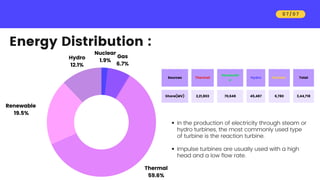
PES College of Engg.
EME Assignment
Impulse Turbines
Presented by Ishan Sharma
Contents
01
01
03
03
02
02
04
04
05
05
Introduction
Build of an Impulse
turbine
Principle and Operation
of Impluse steam turbine
Pressure-Velocity curve
of De-Laval turbine
Thank you
0 2 / 0 7
Introduction
A steam turbine is a machine that extracts thermal
energy from pressurized steam and uses it to do
mechanical work on a rotating output shaft.
Steam turbine can be classified into two types:
• Impulse turbine:
It works on the principle of impulse where kinetic
energy of the force impenges on the blades and
produces force which results in the change in
momentum
• Ex: De laval turbine,curtis turbine
• Reaction turbine:
• It works on the principle of reaction, a reaction
force is developed along with the development of
centrifugal force
•Ex: Parsons turbine
0 3 / 0 7
Build of an
Impulse turbine
0 4 / 0 7
➤ PENSTOCK- It is a large size conduit which conveys water from
high level reservoir to the turbine. The penstock may be of wood,
concrete, or steel.
➤ SPEAR AND NOZZLE-Nozzle is used to convert hydraulic energy
into kinetic energy Spear is so arranged that it can move forward
or backward there by decreasing or increasing the annular area of
nozzle passage.
➤ CASING-Casing is provided to prevent strong splash of
water,which scatter in all directions and to guide the water to the
tail race.
This casing also acts as a safeguard against accidents.
➤ RUNNER WITH BUCKET- The turbine rotor, called the runner, is a
circular disk carrying a number of cup shaped buckets which are
arranged equidistantly around the periphery of the disk.
For low heads the buckets are made of cast iron,but for
higher heads they are made of bronze cast steel,or
stainless steel.
➤ BREAKING JET-when the nozzle is completely closed, the amount
of water striking the runner reduces to zero. But the runner due to
inertia goes on revolving for long time. To stop the runner in short
time, a small nozzle is provided which directs the jet of water on
the back of vanes. This jet of water is called breaking jet.
A centrifugal force is exerted along the curved surfaces
of the blades due to the high kinetic energy of the
steam.
Centrifugal forces cause the blade to move in a circular
manner.
Rotor is a device in which the blades are arranged on
the circumference of the wheel and it converts the
kinetic energy of the steam to rotational energy.
The Rotor is connected to a shaft and when the rotor
starts rotating, it rotates the shaft as well.
The shaft is connected to a generator which convets
the mechanical energy to electrical energy.
Principle and Operation
0 5 / 0 7
Impulse turbine:
Pressure-Velocity
diagram
In the turbine steam initially expands in the nozzle and
pressure decreases and velocity increases,
The high-velocity jet of steam coming out of the
nozzle is then impinge over the curved blades.
The high-velocity of steam transfers it's momentum to
the blades and this causes the blades to rotate.
The change in momentum is caused by centrifugal
force.
0 6 / 0 7
Energy Distribution :
0 7 / 0 7
Thermal
59.6%
Renewable
19.5%
Hydro
12.1%
Gas
6.7%
Nuclear
1.9%
Sources Thermal
Renewabl
e
Hydro Nuclear Total
Share(MV) 2,21,803 70,648 45,487 6,780 3,44,718
In the production of electricity through steam or
hydro turbines, the most commonly used type
of turbine is the reaction turbine.
Impulse turbines are usually used with a high
head and a low flow rate.
THANK
YOU
By: Ishan Sharma
USN-4PS21CS036
Pes Colledge of Engineering
Email-Sharmaishan617@hmail.com

4PS21CS036.pdf

  • 1.
    PES College ofEngg. EME Assignment Impulse Turbines Presented by Ishan Sharma
  • 2.
    Contents 01 01 03 03 02 02 04 04 05 05 Introduction Build of anImpulse turbine Principle and Operation of Impluse steam turbine Pressure-Velocity curve of De-Laval turbine Thank you 0 2 / 0 7
  • 3.
    Introduction A steam turbineis a machine that extracts thermal energy from pressurized steam and uses it to do mechanical work on a rotating output shaft. Steam turbine can be classified into two types: • Impulse turbine: It works on the principle of impulse where kinetic energy of the force impenges on the blades and produces force which results in the change in momentum • Ex: De laval turbine,curtis turbine • Reaction turbine: • It works on the principle of reaction, a reaction force is developed along with the development of centrifugal force •Ex: Parsons turbine 0 3 / 0 7
  • 4.
    Build of an Impulseturbine 0 4 / 0 7 ➤ PENSTOCK- It is a large size conduit which conveys water from high level reservoir to the turbine. The penstock may be of wood, concrete, or steel. ➤ SPEAR AND NOZZLE-Nozzle is used to convert hydraulic energy into kinetic energy Spear is so arranged that it can move forward or backward there by decreasing or increasing the annular area of nozzle passage. ➤ CASING-Casing is provided to prevent strong splash of water,which scatter in all directions and to guide the water to the tail race. This casing also acts as a safeguard against accidents. ➤ RUNNER WITH BUCKET- The turbine rotor, called the runner, is a circular disk carrying a number of cup shaped buckets which are arranged equidistantly around the periphery of the disk. For low heads the buckets are made of cast iron,but for higher heads they are made of bronze cast steel,or stainless steel. ➤ BREAKING JET-when the nozzle is completely closed, the amount of water striking the runner reduces to zero. But the runner due to inertia goes on revolving for long time. To stop the runner in short time, a small nozzle is provided which directs the jet of water on the back of vanes. This jet of water is called breaking jet.
  • 5.
    A centrifugal forceis exerted along the curved surfaces of the blades due to the high kinetic energy of the steam. Centrifugal forces cause the blade to move in a circular manner. Rotor is a device in which the blades are arranged on the circumference of the wheel and it converts the kinetic energy of the steam to rotational energy. The Rotor is connected to a shaft and when the rotor starts rotating, it rotates the shaft as well. The shaft is connected to a generator which convets the mechanical energy to electrical energy. Principle and Operation 0 5 / 0 7
  • 6.
    Impulse turbine: Pressure-Velocity diagram In theturbine steam initially expands in the nozzle and pressure decreases and velocity increases, The high-velocity jet of steam coming out of the nozzle is then impinge over the curved blades. The high-velocity of steam transfers it's momentum to the blades and this causes the blades to rotate. The change in momentum is caused by centrifugal force. 0 6 / 0 7
  • 7.
    Energy Distribution : 07 / 0 7 Thermal 59.6% Renewable 19.5% Hydro 12.1% Gas 6.7% Nuclear 1.9% Sources Thermal Renewabl e Hydro Nuclear Total Share(MV) 2,21,803 70,648 45,487 6,780 3,44,718 In the production of electricity through steam or hydro turbines, the most commonly used type of turbine is the reaction turbine. Impulse turbines are usually used with a high head and a low flow rate.
  • 8.
    THANK YOU By: Ishan Sharma USN-4PS21CS036 PesColledge of Engineering Email-Sharmaishan617@hmail.com