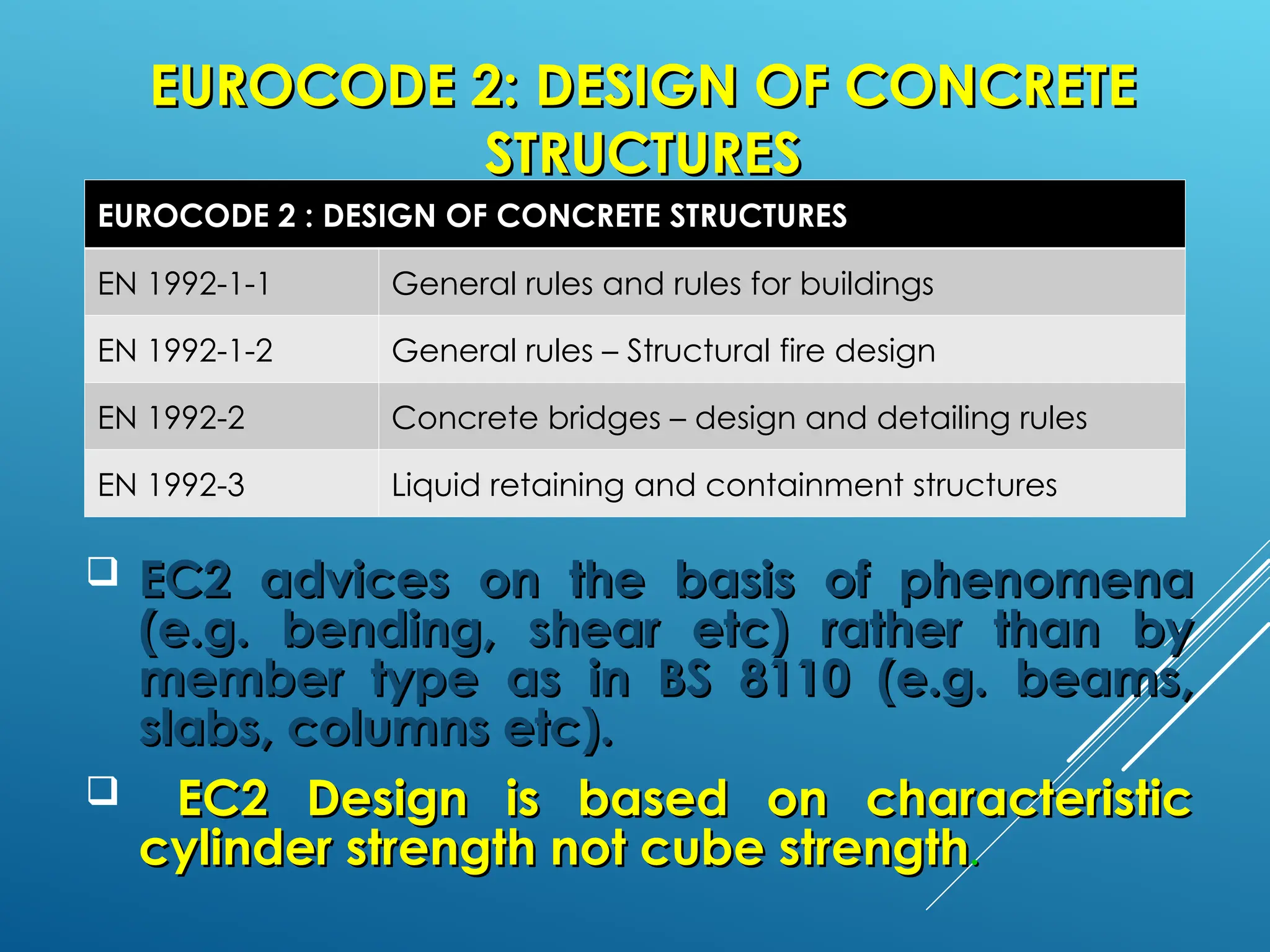
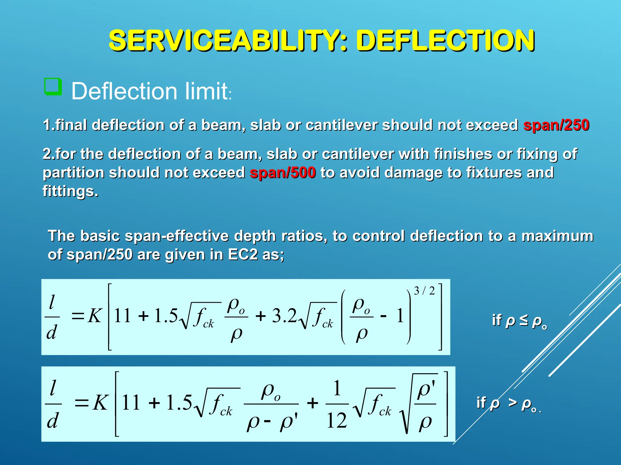
INTRODUCTION
INTRODUCTION
Prepared by:
Prepared by:
Ir.Ts.Dr. Renga Rao Krishnamoorthy
 Get to know your EUROCODE ……..EC2
Get to know your EUROCODE ……..EC2
 Describe Design Philosophies in
Describe Design Philosophies in
accordance to Eurocode 2
 Define SERVICEABILITY LIMIT STATE (SLS)
Define SERVICEABILITY LIMIT STATE (SLS)
 Explain the design criteria addressing SLS
Explain the design criteria addressing SLS
 Calculate the deflection for checking
Calculate the deflection for checking
INTRODUCTION: EUROCODES
The Eurocode Family
EN 1990 Eurocode Basis of structural design
EN 1991 Eurocode 1 Actions on structures
EN 1992 Eurocode 2 Design of concrete structures
EN 1993 Eurocode 3 Design of steel structures
EN 1994 Eurocode 4
Design of composite steel and concrete
structures
EN 1995 Eurocode 5 Design of timber structures
EN 1996 Eurocode 6 Design of masonry structures
EN 1997 Eurocode 7 Geotechnical design
EN 1998 Eurocode 8 Design of structures for earthquake resistance
EN 1999 Eurocode 9 Design of aluminium alloy structures
INTRODUCTION: EUROCODES
 Eurocode underpins all structural design irrespective of the
material of construction. It establishes principles and requirements
for safety, serviceability and durability of structures
EUROCODE 2:
EUROCODE 2: DESIGN OF CONCRETE
DESIGN OF CONCRETE
STRUCTURES
STRUCTURES
 EC2 advices on the basis of phenomena
EC2 advices on the basis of phenomena
(e.g. bending, shear etc) rather than by
member type as in BS 8110 (e.g. beams,
slabs, columns etc).
 EC2 Design is based on characteristic
EC2 Design is based on characteristic
cylinder strength not cube strength
cylinder strength not cube strength.
.
EUROCODE 2 : DESIGN OF CONCRETE STRUCTURES
EN 1992-1-1 General rules and rules for buildings
EN 1992-1-2 General rules – Structural fire design
EN 1992-2 Concrete bridges – design and detailing rules
EN 1992-3 Liquid retaining and containment structures
EUROCODE 2:
EUROCODE 2: DESIGN OF CONCRETE
DESIGN OF CONCRETE
STRUCTURES
STRUCTURES
 The benefits of using EC2 can be
The benefits of using EC2 can be
summarized as followings;
 Technically advanced codes in the world
Technically advanced codes in the world
 Economical compared to BS8110
Economical compared to BS8110
 Logical and avoids repetitions
Logical and avoids repetitions
 More Extensive
More Extensive
 Standardizes design regulations across Europe
Standardizes design regulations across Europe
REINFORCED CONCRETE
REINFORCED CONCRETE
 It is a composite material combining best
It is a composite material combining best
features of
features of concrete
concrete and
and steel
steel
 Invented by Joseph Monier, a French
Invented by Joseph Monier, a French
gardener in 1849 and was patented in 1867
 Why Reinforced Concrete?
Why Reinforced Concrete?
 Strong
Strong
 Durable
Durable
 Formable
Formable
Concrete Steel
Tensile strength
Compressive strength
Shear strength
Durability
Fire resistance
Poor
Good
Fair
Good
Good
Good
Good depending on slenderness
Good
Corrodes
Poor – suffers rapid loss of strength at high
temperatures
MATERIAL PROPERTIES: CONCRETE
 What is concrete?
What is concrete?
Cement + Coarse Aggregate + Fine Aggregate + water
 The quality of concrete depends on the mix-
The quality of concrete depends on the mix-
proportions, types of cement, cement/water ratio
 The concrete strength is measured by crushing
The concrete strength is measured by crushing
strength (compressive test) of cubes or cylinder
 Concrete of a given strength is identified by its
Concrete of a given strength is identified by its
‘class’ – i.e. Class 25/30; where cylinder crushing
strength is 25N/mm
strength is 25N/mm2
2
and cube compressive
strength is 30N/mm
strength is 30N/mm2
2
 Table below shows the class of concrete strength
Table below shows the class of concrete strength
used in EC2
used in EC2
MATERIAL PROPERTIES: CONCRETE
Concrete
strength class
Characteristic
cylinder strength
f ck (N/mm
2
)
Characteristic
cube strength
f ck,cube (N/mm
2
)
Modulus of
elasticity E cm
(kN/mm
2
)
C20/25 20 25 30
C25/30 25 30 31
C30/37 30 37 33
C35/45 35 45 34
C40/50 40 50 35
C45/55 45 55 36
C50/55 50 60 37
C55/67 55 67 38
C60/75 60 75 39
Concrete strength classes and modulus of elasticity
MATERIAL PROPERTIES: STEEL
 Steel strength is assessed by measuring the tensile strength of
Steel strength is assessed by measuring the tensile strength of
steel.
steel.
 A characteristic yield strength (f
A characteristic yield strength (fyk
yk) of 500 N/mm
) of 500 N/mm2
2
which
which
normally denotes as Grade 500 has been adopted by the UK
 The nominal size of a bar is the diameter of an equivalent
The nominal size of a bar is the diameter of an equivalent
circular area.
circular area.
 High-yield bars are manufactured with ribbed surface or in
High-yield bars are manufactured with ribbed surface or in
the form of a twisted square to have a mechanical bond with
the concrete
the concrete
STRESS-STRAIN RELATIONS
 Reinforced concrete
Reinforced concrete
(Concrete + steel
(Concrete + steel
reinforcement) structure
may distorts with resulting
stress and strain when
loaded
loaded
 Stress-strain relation of
Stress-strain relation of
concrete linear at first
(elastic) and eventually
becomes non-linear
becomes non-linear
(plastic)
(plastic)
 The ultimate strain for most
The ultimate strain for most
structural concretes tends
to be constant of 0.0035
Stress-strain Relations
 Compared to concrete,
Compared to concrete,
steel is a high strength
material with a yield
strength between 400 to
600 MPa
600 MPa
 Steel behaves as an
Steel behaves as an
elastic material up to the
yield stress, after which
behaves as a plastic
material
material
 Steel have a elastic
Steel have a elastic
modulus (E
modulus (Es
s) of 200
) of 200
kN/mm
kN/mm2
2
 A design philosophy is a set of assumptions and procedures
which are used to meet the conditions of serviceability,
safety, economy and functionality of the structure. Several
design philosophies have been introduced from different
parts of the world.
Design Philosophy
Design Philosophy
SOME ENGINEERS HAVE ADOPTED THE DESIGN PHILOSOPHY STATED BELOW;
 Working Stress Method(WSM)/ Allowable Stress
Design (ASD)
 Ultimate Load Method (ULM)
Limit State Method(LSM).
LIMIT STATE METHOD (EUROCODE)
dy
nt effects
ormal use
s
Ultimate and serviceability limit states
• Limit states - states beyond which the structure no longer fulfils the
relevant design (performance) criteria
• Ultimate limit states
– loss of equilibrium of the structure as a rigid bo
– failure, collapse, loss of stability
– failure caused by fatigue or other time depende
• Serviceability limit states
- the functioning of the structure under n
- the comfort of people
- the appearance of the construction work
 Deflection limit:
1.
1.final deflection of a beam, slab or cantilever should not exceed
final deflection of a beam, slab or cantilever should not exceed span/250
span/250
2.
2.for the deflection of a beam, slab or cantilever with finishes or fixing of
for the deflection of a beam, slab or cantilever with finishes or fixing of
partition should not exceed
partition should not exceed span/500
span/500 to avoid damage to fixtures and
to avoid damage to fixtures and
fittings.
fittings.
SERVICEABILITY: DEFLECTION
The basic span-effective depth ratios, to control deflection to a maximum
of span/250 are given in EC2 as;




















2
/
3
1
2
.
3
5
.
1
11



 o
ck
o
ck f
f
K
d
l














 '
12
1
'
5
.
1
11 ck
o
ck f
f
K
d
l
if
if ρ
ρ ≤
≤ ρ
ρo
o
if
if ρ
ρ >
> ρ
ρo .
o .
where:
where:
l/d
l/d is the limiting span/depth
is the limiting span/depth
K
K is the factor to take into account the different in structural system
is the factor to take into account the different in structural system
ρ
ρo
ois the reference reinforcement ratio =
is the reference reinforcement ratio = (f
(fck
ck)
) 0.5
0.5
x 10
x 10-3
-3
ρ
ρ is the required tension reinforcement ratio =
is the required tension reinforcement ratio = 100
100A
As,req
s,req /
/ bd
bd
ρ
ρ’
’ is the required compression reinforcement ratio =
is the required compression reinforcement ratio = 100
100A
As
s
’
’
,req
,req /
/ bd
bd
SERVICEABILITY: DEFLECTION
Structural System K
Basic span-effective depth ratio
Concrete highly
stressed, ρ =
1.5%
Concrete lightly
stressed, ρ =
0.5%
1. Simply supported beam, one/two way
simply supported slab
1.0 14 20
2. End span of continuous beam or one-way
continuous slab or two way spanning slab
continuous over one long side
1.3 18 26
3. Interior span of beam or one way or two
way spanning slab
1.5 20 30
4. Slab supported on columns without beam
(flat slab) based on longer span
1.2 17 24
5. Cantilever
0.4 6 8
Table: Basic span/effective depth ratio (fyk
= 500 N/mm2
, C30/35 Concrete)
SERVICEABILITY: DEFLECTION
The basic ratios are modified in particular cases as
follows:
follows:
For flange section where the ratio of the flange width to
For flange section where the ratio of the flange width to
the web width exceeds 3, the values should be multiplied
by 0.8.
by 0.8.
 For beam and slabs, other than flat slab, with spans
For beam and slabs, other than flat slab, with spans
exceeding 7 m, which support partitions liable to be
damaged by excessive deflection, the values should be
multiplied by 7/span.
 Where more tension reinforcement is provided (
Where more tension reinforcement is provided (A
As
s,
,prov
prov)
)
than that calculated (
than that calculated (A
As
s,
, req
req), multiply the values by
), multiply the values by
A
As
s,
,prov
prov/
/A
As,req
s,req. (upper limit = 1.5)
. (upper limit = 1.5)
SERVICEABILITY: DEFLECTION
Example
Example
Think about these!
Think about these!
What if the deflection check failed?
What if the deflection check failed?
How to rectify this problem?
How to rectify this problem?
What are the factors affecting deflection
What are the factors affecting deflection
behavior of a RC beam?
Serviceability: Cracking
Cracks are induced in reinforced concrete
elements as a result of:
flexural tensile stress due to bending under applied
flexural tensile stress due to bending under applied
loads;
loads;
diagonal tension stress due to shear under applied
diagonal tension stress due to shear under applied
load;
load;
volume changes due to shrinkage, creep, thermal and
volume changes due to shrinkage, creep, thermal and
chemical effects; and
splitting along reinforcement due to bond and
splitting along reinforcement due to bond and
anchorage failure.
anchorage failure.
 The primary objective of crack control is to limit the
The primary objective of crack control is to limit the
width of individual cracks.
 This is required not only for aesthetic reasons, but
This is required not only for aesthetic reasons, but
more importantly, for durability and particularly for
corrosion protection of reinforcement.
Serviceability: Cracking
For control of crack, two alternative methods are
described in EC2 clause 7.3.
1.
1. Control of cracking without direct calculation,
Control of cracking without direct calculation,
(Clause 7.3.3)
(Clause 7.3.3)
2.
2. Calculation of crack widths (Clause 7.3.4)
Calculation of crack widths (Clause 7.3.4)
Limiting crack width :
In the absence of specific requirements (e.g. water tightness) the
In the absence of specific requirements (e.g. water tightness) the
crack width may be limited to 0.3 mm in all exposure classes under
quasi-permanent combination of loads.
 In the absence of requirements for appearance, this limit may be
In the absence of requirements for appearance, this limit may be
relaxed to 0.4 mm for exposure classes X0 and XC1.
Serviceability: Cracking
Control of cracking without direct calculation
 Minimum reinforcement area
Minimum reinforcement area
A
As, min
s, min =
= k
kc
c k
k f
fct
ct,
, eff
eff A
Act
ct /
/ f
fyk
yk
 Maximum spacing of reinforcement
Maximum spacing of reinforcement
 Maximum bar size
Maximum bar size
Steel stress
(N/mm2
)
Maximum bar spacing (mm)
wk = 0.4 mm wk = 0.3 mm
160 300 300
200 300 250
240 250 200
280 200 150
320 150 100
360 100 50
Table: Maximum bar spacing for crack control

1
)
5
.
1
35
.
1
(
3
.
0
x
15
.
1 k
k
k
k
yk
s
Q
G
Q
G
f
f



Serviceability: Cracking
Steel stress
(N/mm2
)
Maximum bar size (mm)
wk = 0.4 mm wk = 0.3 mm
160 40 32
200 32 25
240 20 16
280 16 12
320 12 10
360 10 8
400 8 6
450 6 5
Table: Maximum bar diameters for crack control

1
)
5
.
1
35
.
1
(
3
.
0
x
15
.
1 k
k
k
k
yk
s
Q
G
Q
G
f
f



Serviceability: Cracking
CONCLUSION
CONCLUSION
› UNDERSTAND The Type of Eurocodes
UNDERSTAND The Type of Eurocodes
› Materials – Concrete and Reinforcing Steel
Materials – Concrete and Reinforcing Steel
› Stress-strain Relations
Stress-strain Relations
› Design Philosophy
Design Philosophy
› UNDERSTAND LIMIT STATES
UNDERSTAND LIMIT STATES
› Serviceability
Serviceability
 Deflection
Deflection
 Cracking
Cracking
THANK YOU
THANK YOU

407006426-Reinforced-Concrete-Design.ppt

  • 1.
    INTRODUCTION INTRODUCTION Prepared by: Prepared by: Ir.Ts.Dr.Renga Rao Krishnamoorthy Ir.Ts.Dr. Renga Rao Krishnamoorthy
  • 2.
     Get toknow your EUROCODE ……..EC2 Get to know your EUROCODE ……..EC2  Describe Design Philosophies in Describe Design Philosophies in accordance to Eurocode 2 accordance to Eurocode 2  Define SERVICEABILITY LIMIT STATE (SLS) Define SERVICEABILITY LIMIT STATE (SLS)  Explain the design criteria addressing SLS Explain the design criteria addressing SLS  Calculate the deflection for checking Calculate the deflection for checking
  • 7.
    INTRODUCTION: EUROCODES INTRODUCTION: EUROCODES TheEurocode Family EN 1990 Eurocode Basis of structural design EN 1991 Eurocode 1 Actions on structures EN 1992 Eurocode 2 Design of concrete structures EN 1993 Eurocode 3 Design of steel structures EN 1994 Eurocode 4 Design of composite steel and concrete structures EN 1995 Eurocode 5 Design of timber structures EN 1996 Eurocode 6 Design of masonry structures EN 1997 Eurocode 7 Geotechnical design EN 1998 Eurocode 8 Design of structures for earthquake resistance EN 1999 Eurocode 9 Design of aluminium alloy structures
  • 8.
    INTRODUCTION: EUROCODES INTRODUCTION: EUROCODES Eurocode underpins all structural design irrespective of the material of construction. It establishes principles and requirements for safety, serviceability and durability of structures
  • 9.
    EUROCODE 2: EUROCODE 2:DESIGN OF CONCRETE DESIGN OF CONCRETE STRUCTURES STRUCTURES  EC2 advices on the basis of phenomena EC2 advices on the basis of phenomena (e.g. bending, shear etc) rather than by (e.g. bending, shear etc) rather than by member type as in BS 8110 (e.g. beams, member type as in BS 8110 (e.g. beams, slabs, columns etc). slabs, columns etc).  EC2 Design is based on characteristic EC2 Design is based on characteristic cylinder strength not cube strength cylinder strength not cube strength. . EUROCODE 2 : DESIGN OF CONCRETE STRUCTURES EN 1992-1-1 General rules and rules for buildings EN 1992-1-2 General rules – Structural fire design EN 1992-2 Concrete bridges – design and detailing rules EN 1992-3 Liquid retaining and containment structures
  • 10.
    EUROCODE 2: EUROCODE 2:DESIGN OF CONCRETE DESIGN OF CONCRETE STRUCTURES STRUCTURES  The benefits of using EC2 can be The benefits of using EC2 can be summarized as followings; summarized as followings;  Technically advanced codes in the world Technically advanced codes in the world  Economical compared to BS8110 Economical compared to BS8110  Logical and avoids repetitions Logical and avoids repetitions  More Extensive More Extensive  Standardizes design regulations across Europe Standardizes design regulations across Europe
  • 11.
    REINFORCED CONCRETE REINFORCED CONCRETE It is a composite material combining best It is a composite material combining best features of features of concrete concrete and and steel steel  Invented by Joseph Monier, a French Invented by Joseph Monier, a French gardener in 1849 and was patented in 1867 gardener in 1849 and was patented in 1867  Why Reinforced Concrete? Why Reinforced Concrete?  Strong Strong  Durable Durable  Formable Formable Concrete Steel Tensile strength Compressive strength Shear strength Durability Fire resistance Poor Good Fair Good Good Good Good depending on slenderness Good Corrodes Poor – suffers rapid loss of strength at high temperatures
  • 12.
    MATERIAL PROPERTIES: CONCRETE MATERIALPROPERTIES: CONCRETE  What is concrete? What is concrete? Cement + Coarse Aggregate + Fine Aggregate + water Cement + Coarse Aggregate + Fine Aggregate + water  The quality of concrete depends on the mix- The quality of concrete depends on the mix- proportions, types of cement, cement/water ratio proportions, types of cement, cement/water ratio  The concrete strength is measured by crushing The concrete strength is measured by crushing strength (compressive test) of cubes or cylinder strength (compressive test) of cubes or cylinder  Concrete of a given strength is identified by its Concrete of a given strength is identified by its ‘class’ – i.e. Class 25/30; where cylinder crushing ‘class’ – i.e. Class 25/30; where cylinder crushing strength is 25N/mm strength is 25N/mm2 2 and cube compressive and cube compressive strength is 30N/mm strength is 30N/mm2 2  Table below shows the class of concrete strength Table below shows the class of concrete strength used in EC2 used in EC2
  • 13.
    MATERIAL PROPERTIES: CONCRETE MATERIALPROPERTIES: CONCRETE Concrete strength class Characteristic cylinder strength f ck (N/mm 2 ) Characteristic cube strength f ck,cube (N/mm 2 ) Modulus of elasticity E cm (kN/mm 2 ) C20/25 20 25 30 C25/30 25 30 31 C30/37 30 37 33 C35/45 35 45 34 C40/50 40 50 35 C45/55 45 55 36 C50/55 50 60 37 C55/67 55 67 38 C60/75 60 75 39 Concrete strength classes and modulus of elasticity Concrete strength classes and modulus of elasticity
  • 14.
    MATERIAL PROPERTIES: STEEL MATERIALPROPERTIES: STEEL  Steel strength is assessed by measuring the tensile strength of Steel strength is assessed by measuring the tensile strength of steel. steel.  A characteristic yield strength (f A characteristic yield strength (fyk yk) of 500 N/mm ) of 500 N/mm2 2 which which normally denotes as Grade 500 has been adopted by the UK normally denotes as Grade 500 has been adopted by the UK  The nominal size of a bar is the diameter of an equivalent The nominal size of a bar is the diameter of an equivalent circular area. circular area.  High-yield bars are manufactured with ribbed surface or in High-yield bars are manufactured with ribbed surface or in the form of a twisted square to have a mechanical bond with the form of a twisted square to have a mechanical bond with the concrete the concrete
  • 15.
    STRESS-STRAIN RELATIONS STRESS-STRAIN RELATIONS Reinforced concrete Reinforced concrete (Concrete + steel (Concrete + steel reinforcement) structure reinforcement) structure may distorts with resulting may distorts with resulting stress and strain when stress and strain when loaded loaded  Stress-strain relation of Stress-strain relation of concrete linear at first concrete linear at first (elastic) and eventually (elastic) and eventually becomes non-linear becomes non-linear (plastic) (plastic)  The ultimate strain for most The ultimate strain for most structural concretes tends structural concretes tends to be constant of 0.0035 to be constant of 0.0035
  • 16.
    Stress-strain Relations Stress-strain Relations Compared to concrete, Compared to concrete, steel is a high strength steel is a high strength material with a yield material with a yield strength between 400 to strength between 400 to 600 MPa 600 MPa  Steel behaves as an Steel behaves as an elastic material up to the elastic material up to the yield stress, after which yield stress, after which behaves as a plastic behaves as a plastic material material  Steel have a elastic Steel have a elastic modulus (E modulus (Es s) of 200 ) of 200 kN/mm kN/mm2 2
  • 17.
     A designphilosophy is a set of assumptions and procedures which are used to meet the conditions of serviceability, safety, economy and functionality of the structure. Several design philosophies have been introduced from different parts of the world. Design Philosophy Design Philosophy
  • 18.
    SOME ENGINEERS HAVEADOPTED THE DESIGN PHILOSOPHY STATED BELOW;  Working Stress Method(WSM)/ Allowable Stress Design (ASD)  Ultimate Load Method (ULM) Limit State Method(LSM).
  • 19.
    LIMIT STATE METHOD(EUROCODE) dy nt effects ormal use s Ultimate and serviceability limit states • Limit states - states beyond which the structure no longer fulfils the relevant design (performance) criteria • Ultimate limit states – loss of equilibrium of the structure as a rigid bo – failure, collapse, loss of stability – failure caused by fatigue or other time depende • Serviceability limit states - the functioning of the structure under n - the comfort of people - the appearance of the construction work
  • 20.
     Deflection limit: 1. 1.finaldeflection of a beam, slab or cantilever should not exceed final deflection of a beam, slab or cantilever should not exceed span/250 span/250 2. 2.for the deflection of a beam, slab or cantilever with finishes or fixing of for the deflection of a beam, slab or cantilever with finishes or fixing of partition should not exceed partition should not exceed span/500 span/500 to avoid damage to fixtures and to avoid damage to fixtures and fittings. fittings. SERVICEABILITY: DEFLECTION SERVICEABILITY: DEFLECTION The basic span-effective depth ratios, to control deflection to a maximum The basic span-effective depth ratios, to control deflection to a maximum of span/250 are given in EC2 as; of span/250 are given in EC2 as;                     2 / 3 1 2 . 3 5 . 1 11     o ck o ck f f K d l                ' 12 1 ' 5 . 1 11 ck o ck f f K d l if if ρ ρ ≤ ≤ ρ ρo o if if ρ ρ > > ρ ρo . o .
  • 21.
    where: where: l/d l/d is thelimiting span/depth is the limiting span/depth K K is the factor to take into account the different in structural system is the factor to take into account the different in structural system ρ ρo ois the reference reinforcement ratio = is the reference reinforcement ratio = (f (fck ck) ) 0.5 0.5 x 10 x 10-3 -3 ρ ρ is the required tension reinforcement ratio = is the required tension reinforcement ratio = 100 100A As,req s,req / / bd bd ρ ρ’ ’ is the required compression reinforcement ratio = is the required compression reinforcement ratio = 100 100A As s ’ ’ ,req ,req / / bd bd SERVICEABILITY: DEFLECTION SERVICEABILITY: DEFLECTION
  • 22.
    Structural System K Basicspan-effective depth ratio Concrete highly stressed, ρ = 1.5% Concrete lightly stressed, ρ = 0.5% 1. Simply supported beam, one/two way simply supported slab 1.0 14 20 2. End span of continuous beam or one-way continuous slab or two way spanning slab continuous over one long side 1.3 18 26 3. Interior span of beam or one way or two way spanning slab 1.5 20 30 4. Slab supported on columns without beam (flat slab) based on longer span 1.2 17 24 5. Cantilever 0.4 6 8 Table: Basic span/effective depth ratio (fyk = 500 N/mm2 , C30/35 Concrete) SERVICEABILITY: DEFLECTION SERVICEABILITY: DEFLECTION
  • 23.
    The basic ratiosare modified in particular cases as The basic ratios are modified in particular cases as follows: follows: For flange section where the ratio of the flange width to For flange section where the ratio of the flange width to the web width exceeds 3, the values should be multiplied the web width exceeds 3, the values should be multiplied by 0.8. by 0.8.  For beam and slabs, other than flat slab, with spans For beam and slabs, other than flat slab, with spans exceeding 7 m, which support partitions liable to be exceeding 7 m, which support partitions liable to be damaged by excessive deflection, the values should be damaged by excessive deflection, the values should be multiplied by 7/span. multiplied by 7/span.  Where more tension reinforcement is provided ( Where more tension reinforcement is provided (A As s, ,prov prov) ) than that calculated ( than that calculated (A As s, , req req), multiply the values by ), multiply the values by A As s, ,prov prov/ /A As,req s,req. (upper limit = 1.5) . (upper limit = 1.5) SERVICEABILITY: DEFLECTION SERVICEABILITY: DEFLECTION
  • 24.
  • 26.
    Think about these! Thinkabout these! What if the deflection check failed? What if the deflection check failed? How to rectify this problem? How to rectify this problem? What are the factors affecting deflection What are the factors affecting deflection behavior of a RC beam? behavior of a RC beam?
  • 27.
    Serviceability: Cracking Serviceability: Cracking Cracksare induced in reinforced concrete Cracks are induced in reinforced concrete elements as a result of: elements as a result of: flexural tensile stress due to bending under applied flexural tensile stress due to bending under applied loads; loads; diagonal tension stress due to shear under applied diagonal tension stress due to shear under applied load; load; volume changes due to shrinkage, creep, thermal and volume changes due to shrinkage, creep, thermal and chemical effects; and chemical effects; and splitting along reinforcement due to bond and splitting along reinforcement due to bond and anchorage failure. anchorage failure.
  • 28.
     The primaryobjective of crack control is to limit the The primary objective of crack control is to limit the width of individual cracks. width of individual cracks.  This is required not only for aesthetic reasons, but This is required not only for aesthetic reasons, but more importantly, for durability and particularly for more importantly, for durability and particularly for corrosion protection of reinforcement. corrosion protection of reinforcement. Serviceability: Cracking Serviceability: Cracking For control of crack, two alternative methods are For control of crack, two alternative methods are described in EC2 clause 7.3. described in EC2 clause 7.3. 1. 1. Control of cracking without direct calculation, Control of cracking without direct calculation, (Clause 7.3.3) (Clause 7.3.3) 2. 2. Calculation of crack widths (Clause 7.3.4) Calculation of crack widths (Clause 7.3.4)
  • 29.
    Limiting crack width: Limiting crack width : In the absence of specific requirements (e.g. water tightness) the In the absence of specific requirements (e.g. water tightness) the crack width may be limited to 0.3 mm in all exposure classes under crack width may be limited to 0.3 mm in all exposure classes under quasi-permanent combination of loads. quasi-permanent combination of loads.  In the absence of requirements for appearance, this limit may be In the absence of requirements for appearance, this limit may be relaxed to 0.4 mm for exposure classes X0 and XC1. relaxed to 0.4 mm for exposure classes X0 and XC1. Serviceability: Cracking Serviceability: Cracking Control of cracking without direct calculation Control of cracking without direct calculation  Minimum reinforcement area Minimum reinforcement area A As, min s, min = = k kc c k k f fct ct, , eff eff A Act ct / / f fyk yk  Maximum spacing of reinforcement Maximum spacing of reinforcement  Maximum bar size Maximum bar size
  • 30.
    Steel stress (N/mm2 ) Maximum barspacing (mm) wk = 0.4 mm wk = 0.3 mm 160 300 300 200 300 250 240 250 200 280 200 150 320 150 100 360 100 50 Table: Maximum bar spacing for crack control  1 ) 5 . 1 35 . 1 ( 3 . 0 x 15 . 1 k k k k yk s Q G Q G f f    Serviceability: Cracking Serviceability: Cracking
  • 31.
    Steel stress (N/mm2 ) Maximum barsize (mm) wk = 0.4 mm wk = 0.3 mm 160 40 32 200 32 25 240 20 16 280 16 12 320 12 10 360 10 8 400 8 6 450 6 5 Table: Maximum bar diameters for crack control  1 ) 5 . 1 35 . 1 ( 3 . 0 x 15 . 1 k k k k yk s Q G Q G f f    Serviceability: Cracking Serviceability: Cracking
  • 32.
    CONCLUSION CONCLUSION › UNDERSTAND TheType of Eurocodes UNDERSTAND The Type of Eurocodes › Materials – Concrete and Reinforcing Steel Materials – Concrete and Reinforcing Steel › Stress-strain Relations Stress-strain Relations › Design Philosophy Design Philosophy › UNDERSTAND LIMIT STATES UNDERSTAND LIMIT STATES › Serviceability Serviceability  Deflection Deflection  Cracking Cracking
  • 33.