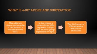
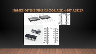
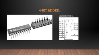
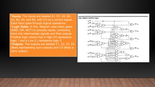
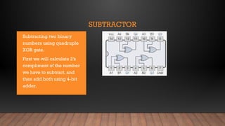
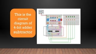
4-Bit Adder
Subtractor
INTRODUCTION:
Abdul Rehman Ansari
Roll no # 241585
Ali Akbar
Roll no #241481
Haider Mustafa
Roll no # 242380
WHAT IS 4-BIT ADDER AND SUBTRACTOR :
This adds two
binary numbers also
it can subtract a
number from the
other.
In this system a
group of four LEDs
represent 1st
input
and an other group
represents 2nd
input.
The third group of
LEDs shows the
result of the
calculation
COMPONENTS:
• Bread boards
• Power supply of 5V
• Jumper wires
• Resisters
• LEDs
• Dip switches
• 4-bit adder
• Quadruple XOR
NAMES OF THE PINS OF XOR AND 4-BIT ADDER
4-BIT ADDER:
Logical symbol:
FUNCTION TABLE Click icon to add picture
•Inputs: Columns labeled A1, B1, A2, and B2 represent
the binary input combinations (L for Low or logic 0, H for
High or logic 1).
•Control Signals (CO): CO indicates the state of a
control input (L or H).
•Outputs: Σ1, Σ2, C2, and others describe the output
behavior under different input and control signal
conditions.
•Inputs: The inputs are labeled A1, B1, A2, B2,
A3, B3, A4, and B4, with CO as a control signal.
Each input goes through logical operations.
•Logic Gates: In this diagram uses basic gates
(AND, OR, NOT) to process inputs, combining
them into intermediate signals and final outputs.
Positive logic means that a High (H) represents
logic 1 and a Low (L) represents logic 0.
•Outputs: The outputs are labeled Σ1, Σ2, Σ3, Σ4
(likely representing sum outputs) and C4 (likely a
carry output).
QUADRUPLE XOR
Input :
It take two inputs per XOR
gate . So, total it requires 8
inputs
Process:
Each XOR processes
inputs by comparing
their logics
Output :
It gives high
output when
inputs differ and
low when they
match
SUBTRACTOR
• Subtracting two binary
numbers using quadruple
XOR gate.
• First we will calculate 2’s
compliment of the number
we have to subtract, and
then add both using 4-bit
adder.
This is the
logical
diagram of
4-bit adder
subtractor
This is the
circuit
diagram of
4-bit adder
subtractor
TINKERCAD 3D MODEL
• https://www.tinkercad.com/things/3ZiugKDvyHb
• This can help us to understand properly.
THANK YOU

4 bit adder and subtractor using 2's complement

  • 1.
  • 2.
    INTRODUCTION: Abdul Rehman Ansari Rollno # 241585 Ali Akbar Roll no #241481 Haider Mustafa Roll no # 242380
  • 3.
    WHAT IS 4-BITADDER AND SUBTRACTOR : This adds two binary numbers also it can subtract a number from the other. In this system a group of four LEDs represent 1st input and an other group represents 2nd input. The third group of LEDs shows the result of the calculation
  • 4.
    COMPONENTS: • Bread boards •Power supply of 5V • Jumper wires • Resisters • LEDs • Dip switches • 4-bit adder • Quadruple XOR
  • 5.
    NAMES OF THEPINS OF XOR AND 4-BIT ADDER
  • 6.
  • 7.
    FUNCTION TABLE Clickicon to add picture •Inputs: Columns labeled A1, B1, A2, and B2 represent the binary input combinations (L for Low or logic 0, H for High or logic 1). •Control Signals (CO): CO indicates the state of a control input (L or H). •Outputs: Σ1, Σ2, C2, and others describe the output behavior under different input and control signal conditions.
  • 8.
    •Inputs: The inputsare labeled A1, B1, A2, B2, A3, B3, A4, and B4, with CO as a control signal. Each input goes through logical operations. •Logic Gates: In this diagram uses basic gates (AND, OR, NOT) to process inputs, combining them into intermediate signals and final outputs. Positive logic means that a High (H) represents logic 1 and a Low (L) represents logic 0. •Outputs: The outputs are labeled Σ1, Σ2, Σ3, Σ4 (likely representing sum outputs) and C4 (likely a carry output).
  • 9.
    QUADRUPLE XOR Input : Ittake two inputs per XOR gate . So, total it requires 8 inputs Process: Each XOR processes inputs by comparing their logics Output : It gives high output when inputs differ and low when they match
  • 10.
    SUBTRACTOR • Subtracting twobinary numbers using quadruple XOR gate. • First we will calculate 2’s compliment of the number we have to subtract, and then add both using 4-bit adder.
  • 11.
    This is the logical diagramof 4-bit adder subtractor
  • 12.
    This is the circuit diagramof 4-bit adder subtractor
  • 13.
    TINKERCAD 3D MODEL •https://www.tinkercad.com/things/3ZiugKDvyHb • This can help us to understand properly.
  • 14.