Download as PDF, PPTX

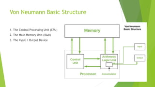
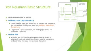

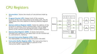
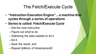
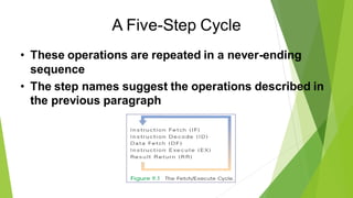
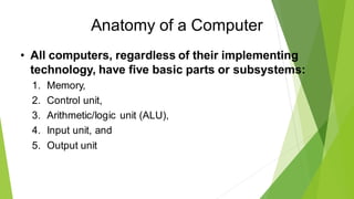
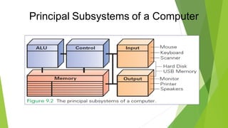

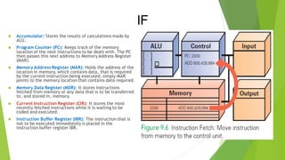
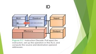

The document provides an overview of computer organization, detailing the core components such as the CPU, memory, and input/output devices, while explaining the fetch/execute cycle through which computers perform operations. It highlights the roles of the arithmetic logic unit, control unit, and various CPU registers, as well as the function of buses in data transmission. Additionally, it touches upon the limitations of computers in terms of creativity and the nature of instruction execution.