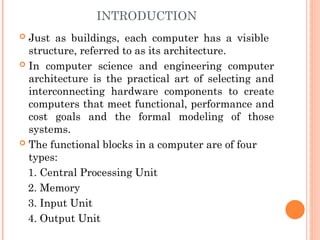
INTRODUCTION
Just asbuildings, each computer has a visible
structure, referred to as its architecture.
In computer science and engineering computer
architecture is the practical art of selecting and
interconnecting hardware components to create
computers that meet functional, performance and
cost goals and the formal modeling of those
systems.
The functional blocks in a computer are of four
types:
1. Central Processing Unit
2. Memory
3. Input Unit
4. Output Unit
4.
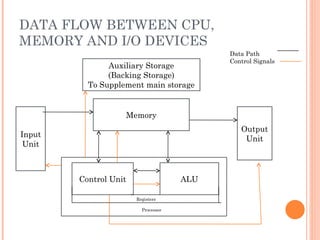
DATA FLOW BETWEENCPU,
MEMORY AND I/O DEVICES
Auxiliary Storage
(Backing Storage)
To Supplement main storage
Memory
Input
Unit
Control Unit ALU
Output
Unit
Registers
Processor
Data Path
Control Signals
5.
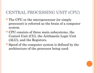
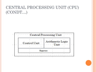
CENTRAL PROCESSING UNIT(CPU)
The CPU or the microprocessor (or simply
processor) is referred as the brain of a computer
system.
CPU consists of three main subsystems, the
Control Unit (CU), the Arithmetic Logic Unit
(ALU), and the Registers.
Speed of the computer system is defined by the
architecture of the processor being used.
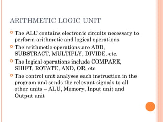
ARITHMETIC LOGIC UNIT
The ALU contains electronic circuits necessary to
perform arithmetic and logical operations.
The arithmetic operations are ADD,
SUBSTRACT, MULTIPLY, DIVIDE, etc.
The logical operations include COMPARE,
SHIFT, ROTATE, AND, OR, etc
The control unit analyses each instruction in the
program and sends the relevant signals to all
other units – ALU, Memory, Input unit and
Output unit
8.
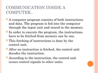
COMMUNICATION INSIDE A
COMPUTER..
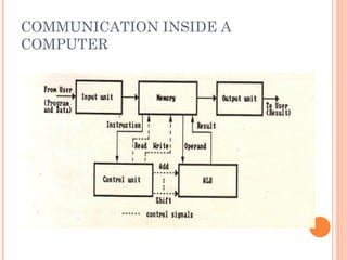
A computer program consists of both instructions
and data. The program is fed into the computer
through the input unit and stored in the memory.
In order to execute the program, the instructions
have to be fetched from memory one by one.
This fetching of instructions is done by the
control unit.
After an instruction is fetched, the control unit
decodes the instruction.
According to the instruction, the control unit
issues control signals to other units.
9.
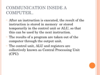
COMMUNICATION INSIDE A
COMPUTER..
oAfter an instruction is executed, the result of the
instruction is stored in memory or stored
temporarily in the control unit or ALU, so that
this can be used by the next instruction.
o The results of a program are taken out of the
computer through the output unit.
o The control unit, ALU and registers are
collectively known as Central Processing Unit
(CPU)
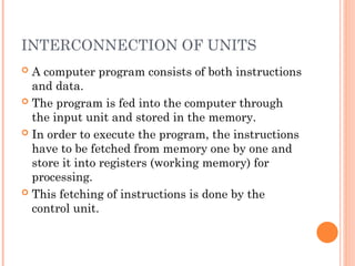
INTERCONNECTION OF UNITS
A computer program consists of both instructions
and data.
The program is fed into the computer through
the input unit and stored in the memory.
In order to execute the program, the instructions
have to be fetched from memory one by one and
store it into registers (working memory) for
processing.
This fetching of instructions is done by the
control unit.
12.
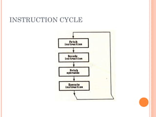
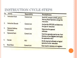
INSTRUCTION CYCLE
Instructionare fetched and executed by the
control unit one by one. The sequences involved
for the fetch of one instruction and its execution
are known as instruction cycle.
REGISTERS
It isa special temporary storage location within the CPU.
Registers quickly accept, store and transfer data and
instructions that are being used immediately.
To execute an instruction, the control unit of the CPU
retrieves it from main memory and places it onto a
register.
The typical operations that take place in the processing of
instruction are part of the instruction cycle or execution
cycle.
The instruction cycle refers to the retrieval of the
instruction from main memory and its sub sequence at
decoding.
The time it takes to go through the instruction cycle is
referred to as I-time.
16.
ARITHMETIC LOGIC UNIT(ALU)
ALU performs all the arithmetic and logical
functions.
It performs arithmetic as well as logical
functions.
The speed of the computer system is defined by
the architecture of the processor being used.
17.
CONTROL UNIT
Itis responsible for directing and coordinating
most of the computer system activities.
It does not execute instructions by itself. It tells
other parts of the computer system what to do.
It determines the movement of electronic signals
between the main memory and arithmetic logic
unit as well as the control signals between the
CPU and input/output devices.
18.
CONTROL UNIT(CONDT…)
Tocomplete an event i.e. processing, control unit
repeats a set of four basic operations:
Fetching is the process of obtaining a program
instruction or data item from the memory
Decoding is the process of translating the
instruction into commands the computer can
execute.
Executing is the process of carrying out the
commands.
Storing is the process of writing the result to
memory.
19.
CONTROL UNIT(CONDT…)
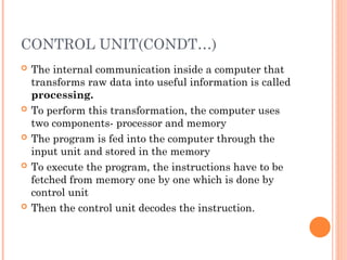
Theinternal communication inside a computer that
transforms raw data into useful information is called
processing.
To perform this transformation, the computer uses
two components- processor and memory
The program is fed into the computer through the
input unit and stored in the memory
To execute the program, the instructions have to be
fetched from memory one by one which is done by
control unit
Then the control unit decodes the instruction.
20.
CONTROL UNIT(CONDT…)
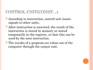
Accordingto instruction, control unit issues
signals to other units.
After instruction is executed, the result of the
instruction is stored in memory or stored
temporarily in the registry, so that this can be
used by the next instruction.
The results of a program are taken out of the
computer through the output unit.
21.
MEMORY
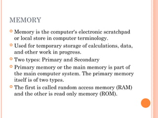
Memory isthe computer's electronic scratchpad
or local store in computer terminology.
Used for temporary storage of calculations, data,
and other work in progress.
Two types: Primary and Secondary
Primary memory or the main memory is part of
the main computer system. The primary memory
itself is of two types.
The first is called random access memory (RAM)
and the other is read only memory (ROM).
22.
RANDOM ACCESS MEMORY(RAM)
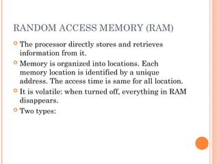
The processor directly stores and retrieves
information from it.
Memory is organized into locations. Each
memory location is identified by a unique
address. The access time is same for all location.
It is volatile: when turned off, everything in RAM
disappears.
Two types:
23.
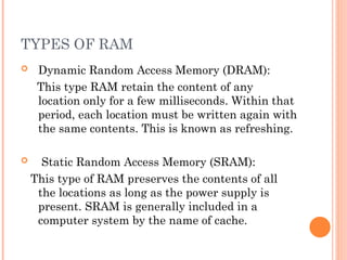
TYPES OF RAM
Dynamic Random Access Memory (DRAM):
This type RAM retain the content of any
location only for a few milliseconds. Within that
period, each location must be written again with
the same contents. This is known as refreshing.
Static Random Access Memory (SRAM):
This type of RAM preserves the contents of all
the locations as long as the power supply is
present. SRAM is generally included in a
computer system by the name of cache.
24.
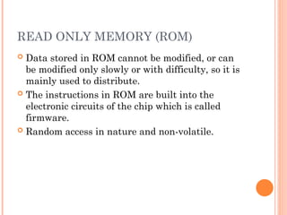
READ ONLY MEMORY(ROM)
Data stored in ROM cannot be modified, or can
be modified only slowly or with difficulty, so it is
mainly used to distribute.
The instructions in ROM are built into the
electronic circuits of the chip which is called
firmware.
Random access in nature and non-volatile.
25.
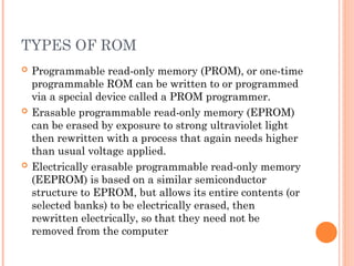
TYPES OF ROM
Programmable read-only memory (PROM), or one-time
programmable ROM can be written to or programmed
via a special device called a PROM programmer.
Erasable programmable read-only memory (EPROM)
can be erased by exposure to strong ultraviolet light
then rewritten with a process that again needs higher
than usual voltage applied.
Electrically erasable programmable read-only memory
(EEPROM) is based on a similar semiconductor
structure to EPROM, but allows its entire contents (or
selected banks) to be electrically erased, then
rewritten electrically, so that they need not be
removed from the computer
26.
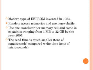
Modern typeof EEPROM invented in 1984.
Random access memories and are non-volatile.
Use one transistor per memory cell and come in
capacities ranging from 1 MB to 32 GB by the
year 2007.
The read time is much smaller (tens of
nanoseconds) compared write time (tens of
microseconds).
27.
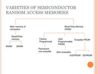
VARIETIES OF SEMICONDUCTOR
RANDOMACCESS MEMORIES
Main memory of
computers
Read Only Memory
(ROM)
Read/Write
memory Factory
Programmed
User
Programmable
PROM
Erasable PROM
SRAM DRAM
Permanent
non-erasable (Non-erasable)
UVEPROM EEPROM
28.
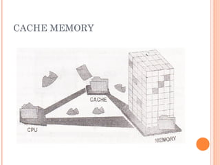
CACHE MEMORY
Highspeed memory kept in between processor
and RAM to increase the data execution speed.
Kept near to the processor.
Major reason for incorporating cache in the
system is that the CPU is much faster than the
DRAM and needs a place to store information
that can be accessed quickly.
Cache fetches the frequently used data from the
DRAM and buffers (stores) it for further
processor usage.
DIFFERENT LEVELS OFCACHE
L1-cache is the fastest cache and it usually comes
within the processor chip itself. L1 cache
typically ranges in size from 8KB to 64KB and
uses the high-speed SRAM instead of the slower
and cheaper DRAM used for main memory.
L2 cache comes between L1 and RAM and is
bigger than the primary cache.
L3 cache is not found nowadays as its function is
replaced by L2 cache. L3 caches are found on the
motherboard rather than the processor. It is kept
between RAM and L2 cache.
31.
PROCESSOR SPEED
Speedof a computer system is determined by
several factors, clock speed of the processor and
the speed and size of the data bus.
Clock speed is the rate at which the processor
processes information and this is measured in
millions of cycles per second(Megahertz)
The more the number of hertz, the faster is the
processing speed
The larger the bus width and the faster the bus
speed, the greater the amount of data can travel
on it in a given amount of time.
32.
INPUT DEVICES
Anyperipheral used to provide data and control
signals to an information processing system such
as a computer or other information appliance.
Common input devices: Keyboard, Mouse
Other devices: microphone, digital camera,
scanner.
33.
OUTPUT DEVICES
Anypiece of computer hardware equipment used
to communicate the results of processed data to
the user.
Examples: Monitors, Printers, Speakers, etc.
34.
LET US SUMMARISE..
Computer organization and architecture is defined
as the science of selecting and interconnecting
hardware components to create computers that
meet functional, performance and cost goals.
The central processing unit is the brain of the
computer system where all the computing is done.
It consists of three main components, the control
unit (CU), the arithmetic logic unit (ALU) and the
registers.
The control unit controls the Input/Output devices
and transfer of data to and from the primary
storage.
35.
ANSWER IN BRIEF
Write a note on computer architecture
What is a system bus? Name the various units of
the system bus.
What is the significance of main memory in
proper functioning of a processor.
What is an Instruction cycle?
36.
ANSWER IN DETAIL
What do you understand by Central Processing
Unit? Describe in details various units of the
CPU.
Write a detailed note on Instruction Cycle
describing the various steps involved.
Describe in details:
a. Processor to Memory Communication
b. Processor to I/O Devices Communication
37.
LET US SUMMARISE..
The Arithmetic Unit is responsible for carrying
out the arithmetic calculations such as addition,
subtraction, multiplication, and division.
The Logic Unit provides CPU the ability to make
logical operations like comparing two data items
and taking different actions based on the results
of the comparison.
Registers are special purpose, high-speed
temporary memory units used by the processor
for holding data.
38.
LET US SUMMARISE..
The System bus is a set of wires used for
interconnection of different units of a computer
system. The three logical units of a system bus
are the address bus, the data bus, and the control
bus.
A cache is a piece of very fast memory, made
from high-speed static RAM that reduces the
access time of the data. It is very expensive and
generally incorporated in the processor, where
valuable data and program segments are kept.
39.
LET US SUMMARISE..
Instructions comprise two parts, namely, the op-
code and the operand. They are transferred one at
a time into the processor, where they are decoded
and the executed.
The Instruction Cycle details the sequence of
events that takes place as an instruction is read
from memory and executed.
In a Fetch Cycle, instruction to be executed is
fetched from the memory to the processor.
The Decode Cycle is responsible for recognizing
which operation the instruction represents
activating the correct circuitry to perform that
operation.
40.
LET US SUMMARISE..
During the Execute Cycle, the operation specified
by the op-code is performed on user provided
data in the ALU.
In the Store Cycle, the results from the execution
cycle are stored back to the memory.
Processors are built with the ability to execute a
limited set of basic operations called the
Instruction Set.
The speed of the processor is measured in
millions of cycles per second or Megahertz (MHz).
41.
LET US SUMMARISE..
Two notables factors on which the speed of a
processor depends are the clock speed of the
processor and the speed and the size of the data
bus
42.
EMBEDDED SYSTEMS:
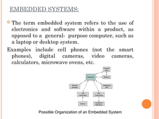
Theterm embedded system refers to the use of
electronics and software within a product, as
opposed to a general- purpose computer, such as
a laptop or desktop system.
Examples include cell phones (not the smart
phones), digital cameras, video cameras,
calculators, microwave ovens, etc.
Possible Organization of an Embedded System
43.
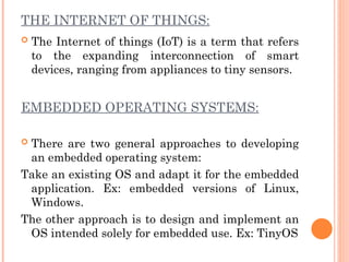
THE INTERNET OFTHINGS:
The Internet of things (IoT) is a term that refers
to the expanding interconnection of smart
devices, ranging from appliances to tiny sensors.
EMBEDDED OPERATING SYSTEMS:
There are two general approaches to developing
an embedded operating system:
Take an existing OS and adapt it for the embedded
application. Ex: embedded versions of Linux,
Windows.
The other approach is to design and implement an
OS intended solely for embedded use. Ex: TinyOS
44.
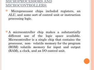
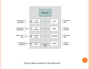
MICROPROCESSORS AND
MICROCONTROLLERS:
Microprocessorchips included registers, an
ALU, and some sort of control unit or instruction
processing logic.
A microcontroller chip makes a substantially
different use of the logic space available.
Microcontroller is a single chip that contains the
processor, non- volatile memory for the program
(ROM) volatile memory for input and output
(RAM), a clock, and an I/O control unit.
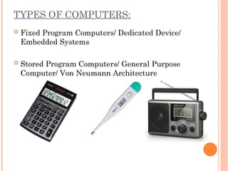
TYPES OF COMPUTERS:
Fixed Program Computers/ Dedicated Device/
Embedded Systems
Stored Program Computers/ General Purpose
Computer/ Von Neumann Architecture
47.
STORED PROGRAM COMPUTERS:
Stored-program computer, a computer that stores
instructions in its memory to enable it to perform
a variety of tasks in sequence or intermittently.
48.
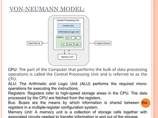
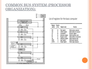
VON-NEUMANN MODEL:
CPU: Thepart of the Computer that performs the bulk of data processing
operations is called the Central Processing Unit and is referred to as the
CPU.
ALU: The Arithmetic and Logic Unit (ALU) performs the required micro-
operations for executing the instructions.
Registers: Registers refer to high-speed storage areas in the CPU. The data
processed by the CPU are fetched from the registers.
Bus: Buses are the means by which information is shared between the
registers in a multiple-register configuration system.
Memory Unit: A memory unit is a collection of storage cells together with
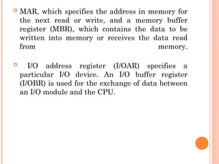
MAR, whichspecifies the address in memory for
the next read or write, and a memory buffer
register (MBR), which contains the data to be
written into memory or receives the data read
from memory.
I/O address register (I/OAR) specifies a
particular I/O device. An I/O buffer register
(I/OBR) is used for the exchange of data between
an I/O module and the CPU.
51.
INSTRUCTION CYCLE STATE
DIAGRAM:
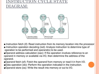
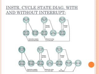
■Instruction fetch (if): Read instruction from its memory location into the processor
■ Instruction operation decoding (iod): Analyze instruction to determine type of
operation to be performed and operand(s) to be used.
■Operand address calculation (oac): If the operation involves reference to an
operand in memory or available via I/O, then determine the address of the
operand.
■Operand fetch (of): Fetch the operand from memory or read it in from I/O.
■Data operation (do): Perform the operation indicated in the instruction.
■Operand store (os): Write the result into memory or out to I/O.
52.
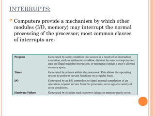
INTERRUPTS:
Computers providea mechanism by which other
modules (I/O, memory) may interrupt the normal
processing of the processor; most common classes
of interrupts are-
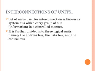
INTERCONNECTIONS OF UNITS..
Set of wires used for interconnection is known as
system bus which carry group of bits
(information) in a controlled manner.
It is further divided into three logical units,
namely the address bus, the data bus, and the
control bus.
57.
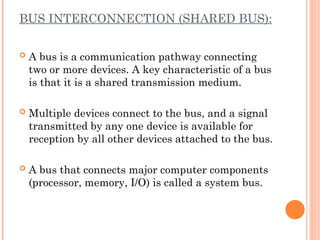
BUS INTERCONNECTION (SHAREDBUS):
A bus is a communication pathway connecting
two or more devices. A key characteristic of a bus
is that it is a shared transmission medium.
Multiple devices connect to the bus, and a signal
transmitted by any one device is available for
reception by all other devices attached to the bus.
A bus that connects major computer components
(processor, memory, I/O) is called a system bus.
58.
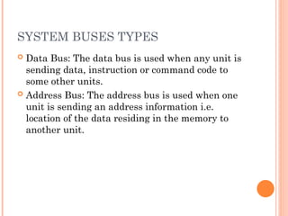
SYSTEM BUSES TYPES
Data Bus: The data bus is used when any unit is
sending data, instruction or command code to
some other units.
Address Bus: The address bus is used when one
unit is sending an address information i.e.
location of the data residing in the memory to
another unit.
59.
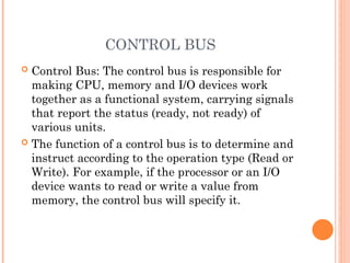
CONTROL BUS
ControlBus: The control bus is responsible for
making CPU, memory and I/O devices work
together as a functional system, carrying signals
that report the status (ready, not ready) of
various units.
The function of a control bus is to determine and
instruct according to the operation type (Read or
Write). For example, if the processor or an I/O
device wants to read or write a value from
memory, the control bus will specify it.
60.
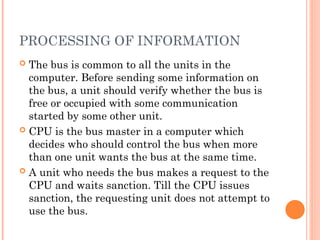
PROCESSING OF INFORMATION
The bus is common to all the units in the
computer. Before sending some information on
the bus, a unit should verify whether the bus is
free or occupied with some communication
started by some other unit.
CPU is the bus master in a computer which
decides who should control the bus when more
than one unit wants the bus at the same time.
A unit who needs the bus makes a request to the
CPU and waits sanction. Till the CPU issues
sanction, the requesting unit does not attempt to
use the bus.
61.
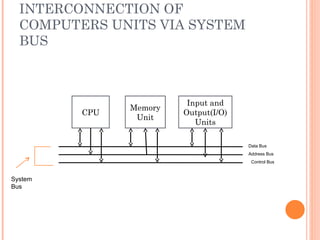
INTERCONNECTION OF
COMPUTERS UNITSVIA SYSTEM
BUS
CPU
Input and
Output(I/O)
Units
Memory
Unit
Data Bus
Address Bus
Control Bus
System
Bus
62.
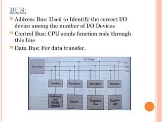
BUS:
Address Bus:Used to Identify the correct I/O
device among the number of I/O Devices
Control Bus: CPU sends function code through
this line
Data Bus: For data transfer.
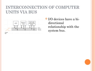
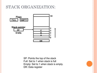
63.
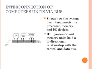
INTERCONNECTION OF
COMPUTERS UNITSVIA BUS
Shows how the system
bus interconnects the
processor, memory
and I/O devices.
Both processor and
memory units hold a
bi-directional
relationship with the
control and data bus.
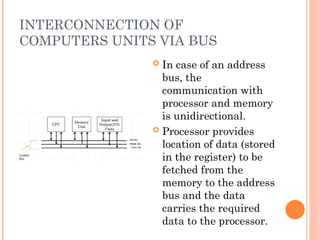
64.
INTERCONNECTION OF
COMPUTERS UNITSVIA BUS
In case of an address
bus, the
communication with
processor and memory
is unidirectional.
Processor provides
location of data (stored
in the register) to be
fetched from the
memory to the address
bus and the data
carries the required
data to the processor.
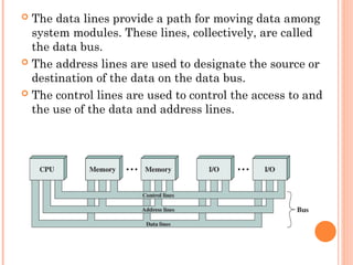
The datalines provide a path for moving data among
system modules. These lines, collectively, are called
the data bus.
The address lines are used to designate the source or
destination of the data on the data bus.
The control lines are used to control the access to and
the use of the data and address lines.
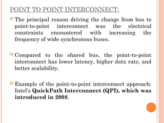
POINT TO POINTINTERCONNECT:
The principal reason driving the change from bus to
point-to-point interconnect was the electrical
constraints encountered with increasing the
frequency of wide synchronous buses.
Compared to the shared bus, the point-to-point
interconnect has lower latency, higher data rate, and
better scalability.
Example of the point-to-point interconnect approach:
Intel’s QuickPath Interconnect (QPI), which was
introduced in 2008.
69.
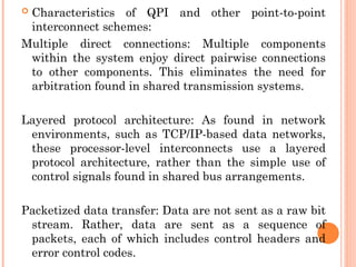
Characteristics ofQPI and other point-to-point
interconnect schemes:
Multiple direct connections: Multiple components
within the system enjoy direct pairwise connections
to other components. This eliminates the need for
arbitration found in shared transmission systems.
Layered protocol architecture: As found in network
environments, such as TCP/IP-based data networks,
these processor-level interconnects use a layered
protocol architecture, rather than the simple use of
control signals found in shared bus arrangements.
Packetized data transfer: Data are not sent as a raw bit
stream. Rather, data are sent as a sequence of
packets, each of which includes control headers and
error control codes.
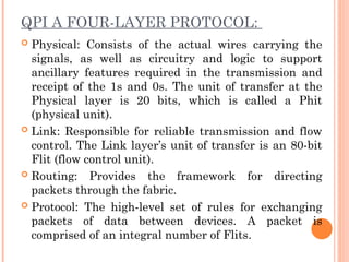
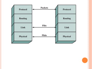
QPI A FOUR-LAYERPROTOCOL:
Physical: Consists of the actual wires carrying the
signals, as well as circuitry and logic to support
ancillary features required in the transmission and
receipt of the 1s and 0s. The unit of transfer at the
Physical layer is 20 bits, which is called a Phit
(physical unit).
Link: Responsible for reliable transmission and flow
control. The Link layer’s unit of transfer is an 80-bit
Flit (flow control unit).
Routing: Provides the framework for directing
packets through the fabric.
Protocol: The high-level set of rules for exchanging
packets of data between devices. A packet is
comprised of an integral number of Flits.
73.
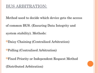
BUS ARBITRATION:
Method usedto decide which device gets the access
of common BUS. (Ensuring Data Integrity and
system stability). Methods:
Daisy Chaining (Centralised Arbitration)
Polling (Centralised Arbitration)
Fixed Priority or Independent Request Method
(Distributed Arbitration)
74.
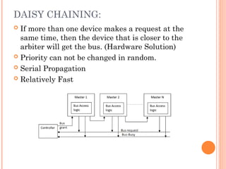
DAISY CHAINING:
Ifmore than one device makes a request at the
same time, then the device that is closer to the
arbiter will get the bus. (Hardware Solution)
Priority can not be changed in random.
Serial Propagation
Relatively Fast
75.
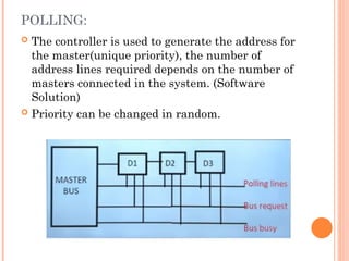
POLLING:
The controlleris used to generate the address for
the master(unique priority), the number of
address lines required depends on the number of
masters connected in the system. (Software
Solution)
Priority can be changed in random.
76.
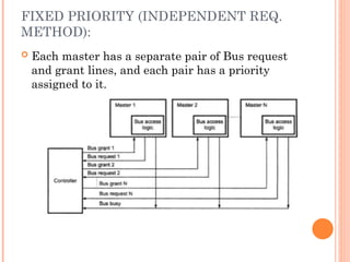
FIXED PRIORITY (INDEPENDENTREQ.
METHOD):
Each master has a separate pair of Bus request
and grant lines, and each pair has a priority
assigned to it.
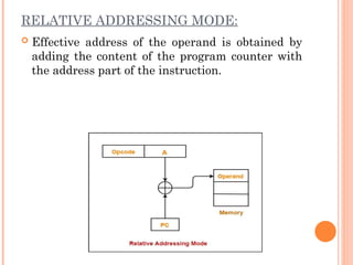
ADDRESSING MODE:
Specifiesdifferent ways possible in which
reference to the operand can be made.
Effective address: Final address of the location
where the operand is stored. Calculation of
effective address can be done in two ways:
1. Non computable addressing
2. Computable addressing (involves arithmetic)
83.
CRITERIA FOR DIFFERENT
ADDRESSINGMODE:
It should be fast
The length of the instruction must be small
They should support pointers
Should support looping constructs, indexing of
data structure.
Program relocation.
84.
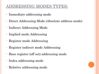
ADDRESSING MODES TYPES:
oImmediate addressing mode
o Direct Addressing Mode (Absolute address mode)
o Indirect Addressing Mode
o Implied mode Addressing
o Register mode Addressing
o Register indirect mode Addressing
o Base register (off set) addressing mode
o Index addressing mode
o Relative addressing mode
85.
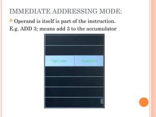
IMMEDIATE ADDRESSING MODE:
Operand is itself is part of the instruction.
E.g. ADD 3; means add 3 to the accumulator
86.
Advantages:
•Can be usedfor constants
•Extremely fast, no memory reference is required
Disadvantages:
•Cannot be used with variables
•Cannot be used for large constant values
Application:
•Mostly used when required data is directly moved
to required register or memory
87.
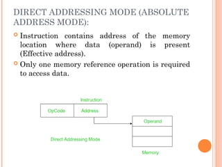
DIRECT ADDRESSING MODE(ABSOLUTE
ADDRESS MODE):
Instruction contains address of the memory
location where data (operand) is present
(Effective address).
Only one memory reference operation is required
to access data.
88.
Advantages:
•With variables, simplestaddressing mode
•No restriction on range of data.
•Can be used to access global variables whose
address is known at compile time.
Disadvantages:
•Relatively Slow
•Number of variables used are limited.
•In large calculation it will fail.
89.
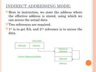
INDIRECT ADDRESSING MODE:
Here in instruction, we store the address where
the effective address is stored, using which we
can access the actual data.
Two references are required.
1st
is to get EA, and 2nd
reference is to access the
data.
90.
Advantages:
•No limitation onnumber of variable or size of
variable
•Implementation of pointer are feasible and
relatively more secure.
Disadvantage:
•Relatively slow as memory must be referred more
than one time.
91.
IMPLIED MODE ADDRESSING:
Operands are specified implicitly in the
definition of the instruction.
Register reference instructions use an
accumulator are implied mode
Zero address Instruction, also known as stack
addressing mode.
E.g. Increment accumulator, complement
accumulator.
92.
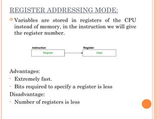
REGISTER ADDRESSING MODE:
Variables are stored in registers of the CPU
instead of memory, in the instruction we will give
the register number.
Advantages:
• Extremely fast.
• Bits required to specify a register is less
Disadvantage:
• Number of registers is less
93.
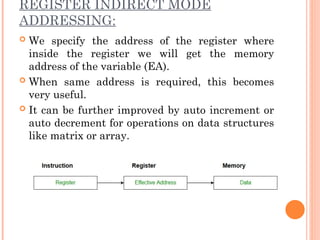
REGISTER INDIRECT MODE
ADDRESSING:
We specify the address of the register where
inside the register we will get the memory
address of the variable (EA).
When same address is required, this becomes
very useful.
It can be further improved by auto increment or
auto decrement for operations on data structures
like matrix or array.
94.
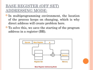
BASE REGISTER (OFFSET)
ADDRESSING MODE:
In multiprogramming environment, the location
of the process keeps on changing, which is why
direct address will create problem here.
To solve this, we save the starting of the program
address in a register (BR).
95.
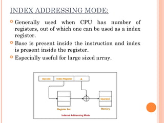
INDEX ADDRESSING MODE:
Generally used when CPU has number of
registers, out of which one can be used as a index
register.
Base is present inside the instruction and index
is present inside the register.
Especially useful for large sized array.
96.
RELATIVE ADDRESSING MODE:
Effective address of the operand is obtained by
adding the content of the program counter with
the address part of the instruction.
Editor's Notes
#12 In all computer languages, expressions consist of two types of components: operands and operators. Operands are the objects that are manipulated and operators are the symbols that represent specific actions. For example, in the expression
5 + x
X and 5 are operands and + is an operator. All expressions have at least one operand.
#13 In all computer languages, expressions consist of two types of components: operands and operators. Operands are the objects that are manipulated and operators are the symbols that represent specific actions. For example, in the expression
5 + x
X and 5 are operands and + is an operator. All expressions have at least one operand.