SlideShare a Scribd company logo
1 of 35
Download to read offline
QEG SYSTEM DESCRIPTION 3-25-2014
The Quantum Electric Generator system (QEG) is an adaptation of one of Nikola Tesla’s many patented electrical
generator / dynamo / alternator designs. The particular patent referenced is No. 511,916, titled simply “Electric
Generator”, and dated January 2, 1894 (see back of this manual). The adaptation is a conversion from a linear
system, to a rotary system.
The QEG prototype is scaled to produce electrical power in the range of 10-15 kW (kilowatts) continuously, and
can be set up to provide either 120 Volt or 230-240 Volt single phase output. We are also planning future
designs to provide 3-phase power.
Service life of the device is limited only by certain replaceable components, such as bearings, v-belts, and
capacitors. The basic machine should operate trouble-free (with minimal maintenance) for as long as any good
quality electro-mechanical appliance, such as a quality washing machine or refrigerator. Heavy-duty mechanical
components are used throughout for reliability.
The QEG is not a complicated device, as it is designed (like Tesla’s other ‘discoveries’), to work in harmony with
natural laws, rather than with the power-wasting symmetric motor and generator designs used in today’s
mainstream industry.
An effective way to understand the operating principle of the QEG is to think of it as a high-powered, self-
resonant oscillator (a power tank circuit), which generates high-voltage AC (15 to 25kV). These HV oscillations
are then transformed into line voltage AC output, at current levels up to approximately 85 A. In today’s
alternative energy terminology, it would be called a type of resonance machine.
The circuitry that develops high power in this device is really based on an existing but under-utilized power
oscillator configuration, however, the ‘quantum’ part of the design has to do with how the generator output is
tuned for maximum power. Conventional alternators (AC generators) consume more input power than the
output power they provide. For example, one brand of power take off (PTO) alternator uses 18,000 watts (24
horsepower) to develop 13,000 watts of output power. In the QEG, input power is used only to maintain
resonance in the core, which uses a small fraction of the output power (under 1000 watts to produce 10,000
watts), and once running, the QEG provides this power to its own 1 horsepower motor. This is known as over-
unity. Once the machine builds up to the resonant frequency, it powers itself (self-running).
In the QEG, the exciter coil is used to provide a conduction path through the quantum field (zero point) into the
generator core. This has the effect of polarizing the core, which increases power output over time.
James M. Robitaille
NOTICE
TO BE READ AND UNDERSTOOD BY ALL QEG PROJECT CREWS
Fix the World (FTW) is not responsible for the actions of others. We can only tell you our
experience. We have discovered it is essential that those wishing to build a QEG use careful
thinking, patience, and consideration for the greater good.
The inhabitants of planet Earth are entering into a new paradigm and a new way of doing
business. In honor of Nikola Tesla, the QEG is a gift freely given to the world, and FTW’s
involvement is strictly altruistic.
The QEG is an electromechanical device and as such, safety for the individual and end user should
always be of prime concern. It is therefore essential that persons assembling the device are
experienced in the field of electro-mechanical assembly. A considerable level of knowledge in
quantum physics is also required.
IF YOU ARE TRAINED IN TRADITIONAL PHYSICS, AND HAVE NOT BEEN DOING THIS WORK
FOR MANY YEARS, YOU MUST FIRST DO YOUR RESEARCH ON BASIC QUANTUM ENERGY
DEVICES AND HOW THEY WORK (e.g. resonance and tuning).
Electrical / Mechanical devices are inherently dangerous. Electrical shock hazards can cause
serious injury and in some cases death. Mechanical hazards can result in dismemberment and in
some cases death.
Due diligence has been applied to ensure that the QEG instructions are complete and correct. All
local and country-specific electrical and mechanical code implications, by which a QEG might be
installed and operated, cannot possibly be known. Nor is it conceivable that any and all possible
hazards and/or results of each procedure or method have been accounted for.
It is for these reasons that the QEG must be either directly installed or supervised by an
experienced electromechanical engineer to ensure the installation is done safely and in
accordance with local electrical code, however, the QEG is installed the same way as any
commercial generator and does not violate any electrical codes. Anyone who uses the QEG
installation instructions (including but not limited to any procedure or method of installation)
must first satisfy themselves that neither their safety, nor the safety of the end user, will be
endangered over the course of the installation and operation of the QEG.
It is imperative to understand YOU NEED PROFESSIONALS AND EXPERT ADVICE to build a
QEG.
The installation instructions are designed to show how we have found the building of the device to
be accomplished, and any negative outcomes that result are completely the responsibility of the
person/company building it; FTW provides no guarantee for the successful installation of the QEG.
This notice serves the purpose of communicating the serious nature of building a quantum
machine, as we are well aware that there have been severe restrictive agencies involved with their
suppression. Quantum free energy isn’t taught at University and most designers have heretofore
been unsuccessful at mass distribution. It is YOUR RESPONSIBILITY therefore to make certain you
are building the QEG with positive intentions for humanity, and lashing out legally or otherwise to
FTW, HopeGirl and/or the designer and his family, is a violation of goodwill and will in no way be
attended to. We know of no other way to do this but to go back to the “HONOR SYSTEM.”
In reading this notice I agree that:
1) I WILL NOT ATTEMPT TO BUILD A QEG UNLESS I DO SO APPROPRIATELY WITH AN
ELECTROMECHANCIAL ENGINEERING PROFESSIONAL.
2) I WILL NOT COMMISSION (TURN ON) OR INSTALL THE QEG WITHOUT AN
ELECTROMECHANICAL ENGINEERING PROFESSIONAL.
3) UNDER THE ABOVE CONDITIONS, I MAY USE THE QEG INSTALLATION INSTRUCTIONS FOR
PERSONAL USE, AND UNDERSTAND THE NEED FOR IMPECCABLE COMMITMENT TO THE
BETTERMENT OF HUMANITY. IN THE BEST INTEREST OF THE PEOPLE OF PLANET EARTH, I
WILL NOT ATTEMPT TO MISUSE OR MONOPOLIZE THE QEG INSTALLATION INSTRUCTIONS IN
ANY CAPACITY, NOR WILL I ATTEMPT TO MAKE A HUGE PROFIT AT THE EXPENSE OF ANOTHER
HUMAN BEING.
IMPORTANT – Please make certain that persons who are to use this equipment thoroughly
read and understand these instructions and any additional instructions prior to
construction, installation and operation. In addition, we require you to read this notice
again when you are ready to assemble the core.
Letter from the Editor 3-25-2014
Dear Builder,
It is no easy task to build the QEG, and we want to encourage you by offering a short treatise on
the importance of ‘consciousness’ in this endeavor. Many are becoming more familiar with
Nikola Tesla, his desire for all people to have access to free energy, and his failed attempt to
expose this technology to the world. Many have followed him with the same aspirations and,
similar to Tesla’s plight, have also been prevented by powers beyond their control. The “free”
energy movement is rife with horror stories ranging from government theft of patents, to
reputations destroyed, to the murder of untold numbers of brilliant scientists/inventors.
We must all consciously and constantly rise above these tyrannical infringements, and create an
environment for ourselves and our neighbors, and rediscover Nature’s Laws to be able to live
and thrive. We must leave off responding in incredulity to what was “done to us” when we were
told and believed we couldn’t create free energy. We are now awake to the point that we know
they were lying. Who’s they? The elite for starters – follow the money (watch THRIVE); J.P.
Morgan couldn’t put a meter on an energy plan for the world, and so destroyed any chance of
that happening through several vicious attacks on Tesla’s reputation and livelihood – basically
got Tesla’s ideas out of the way for his own profit and power – and maliciously destroyed the
man (youtube: Tesla’s Autobiography). While the electric companies have told the people theirs
is the only way to get electricity, and we are dependent on them, the truth is that we have been
deprived of this alternative (quantum) energy source for close to 130 years. Morgan’s grip on the
energy supply has not loosened one bit in all that time, in fact, you are probably paying more for
electricity than ever before, all things being equal.
So how do we effect our future now, and free ourselves and the generations to come after us
completely from energy tyranny? Building the QEG is one way. It is a journey that requires you
think deeply about processes that will, in turn, expand your senses to enable you to receive
information from the quantum field of consciousness, or God if you prefer this reference. We
believe we had Divine inspiration and help, which began with a burning desire to “get off the
grid” and also do something significant for humanity. The timing is wonderful because, as of the
writing of this, the entire planet is in turmoil as never before, and people will need to not only be
self-sufficient, we will all need to live according to what is good for all (Ubuntu), and help each
other for our continued evolution as species/planet.
It is with great love that the QEG is offered to the world, and as you take on the task of building
one, it is hoped that this becomes your path also: the mission of free energy for all! The next step
we ask you to take on your journey, before and during building, is to listen to the discussion
here: http://www.youtube.com/watch?v=3FqzTW7qh2U&feature=youtu.be with HopeGirl,
Ralph and Marsha Ring, Fernando Vossa and the 3D Global Network.
I am, in service to Gaia and its inhabitants, deeply grateful for this technology, and the
opportunity to share it!
Valerie Robitaille
IMPORTANT ADDITIONAL INFORMATION
We are not professional writers or photographers and didn’t always have opportunities to
document or photograph every step of development. Therefore, please take the level of
engineer/electrical experience required to build a QEG very seriously as we are giving
these to you under this premise. You will discover the advanced level of knowledge of
mechanical/electrical processes needed quickly enough. The correct construction of the
QEG requires patience and careful thought. We made several mistakes in development and
have given here the steps that were successful. You will probably still make mistakes – and
these will be your greatest learning opportunities as you gain more knowledge about this
type of energy.
Before beginning to build, consider how much you would like to outsource to one of the
cottage industry community units (CICUs) near you! In the US we recommend Polaris for
the steel stator/rotor construction, and Torelco for toroidal winding. As FTW continues to
roll out the distribution plan, and more connections across the world are made, we think
CICUs will be commonplace and hence, QEG parts accessible (many people will be making
them!)
When website URLs were available we provided links for the person reading this online.
You may certainly use your own sources for materials but it is imperative you do not alter
the instructions/parts herein if you are building a QEG. (We know with increased
knowledge you will discover many applications for this technology.) When photographs
can be shown to help you visualize a process, they are provided. Please remember, we are
not professional manual writers. What we offer you here is free of charge and our gift to
humanity – but it comes with great responsibility. Learn as much as you can, use
discernment and wisdom, share freely, and you will be privileged to know the secrets of
energy creation from the quantum field.
We would like to dedicate the success we’ve experienced to our first teacher, Sir Timothy
Thrapp, and WITTS Ministries, without whose guidance none of this would be available so
soon. We acknowledge and honor the work WITTS has done for over 200 years bringing
technology forward, and hope that you will consider making a donation to the ministry for
their great work.
We would also like to thank our greatest teacher and fellow humanitarian, Nikola Tesla. It
is our most gratifying honor to present modern plans for a quantum energy generator to
the world, based on Tesla’s discoveries, especially at a time when we the people are being
manipulated and controlled by a corrupt energy economy. Tesla wanted everyone on the
planet to have energy. We continue to carry out his vision.
SCHEMATIC
Parts List
Part Type, Model # or MFG PN Quantity
Capacitors
Ceramic Disc Capacitors 15pF 3150volts 2
Film Capacitors 2.5uF 2000V 12
End Plates and Shrouds
Fiberglass reinforced epoxy
laminate (for 2 end plates)
G10/FR4 (1) sheet ½ inch thick by 3
feet by 4 feet
Fiberglass reinforced epoxy
laminate (shrouds)
G10/FR4 (2) 1/8” x 5.875” diameter
Exciter Coil
Clear Cast Acrylic Tube 4-3/4” OD x 4-1/2” ID, 1’
Length
1
#10 Magnet wire (see
generator core)
V-Belts and Pulleys
Goodyear 4L430 V-Belt GDYR_4L430 1
1 Groove, 3” x 7/8” bore, type
A Pulley (Motor)
AK30 x 7/8 1
1 Groove 2.50” Pulley 7/8”
bore type A (Generator)
AK25X7/8 1
Drive Motor DC PM Variable Speed, 2500
RPM, 180V armature, 7/8”
shaft, with base
1
Generator Core
Spacer Blocks 1-1/2” x 1-1/2”
x 4-1/2”
Aluminum 6061-T6 16
Mica Tape 1.00” x 50YD MICA77956X1X50 1
Bonder for shaft/rotor LOCTITE 648 1
7387 Activator (use with
bonder)
1.75oz
Mica Plate NEMA 6 36” x 36” x .030 1
7/8” Three Bolt Flange
Bearings
SATRD205-14G 2
Magnet Wire #10 Round HPT
or HAPT
~620’
Magnet Wire #20 Round Pulse
Shield
HTAIHSD 6” SPL/060-Heavy
MW35, 73, 36
~5200’
Teflon tubing TFT20019 NA005 (Alpha
Wire)
8 pieces (12” each)
Fiberglass sleeving w/PVC for
#10 HAPT wire (tubing)
PF1308 8 pieces (12” each)
Tape, white, 1”fiberglass, hi-
temp (outer wrap) RG48 (Intertape)
2 rolls
Tape, black, 1” reinforced,
high-strength
60020719 (Von Roll) 2 rolls
Nomex Corner Insulation Torelco 16
Shafting 7/8” dia. x 11.0” long
w/standard 3/16” x 3/32”
keyway
C1045 TGP Trukey 7/8” dia. x 11”
8 inch Bolts, ¼ - 28 thread,
Grade 8
1050095555 (Instock
Fasteners)
8
Electrical Terminals
Assorted ring, spade, and
quick connect terminals
Additional Parts
Variac, 120/240V in, 0-280V
out, 9.5 Amps
Type 1520 (STACO) 1
Console Box w/panel 1456FG4BKBU (Hammond
Mfg.)
1
Plexiglass sheet for mounting
2.5uF capacitors
¼ inch thick by 12 inches sq. 1
Electrical box 4” x 4” 1
50 amp plug 1
50 amp receptacle 1
Switch, start/run DPDT center off, 15 amp,
240V
1
Bridge Rectifier 600 volt, 25 Amp., quick
connect terminals
1
Nuts ¼ - 28 Grade 8 8
Washers ¼ “ flat 16
Frame and Base
Angle aluminum 1 ½” x 1 ½” x 4 feet. 1/8” thk. 1
Suppliers and Parts/Service List
POLARIS LASER LAMINATIONS – Generator Core; Rotor
TORELCO – Toroidal winding service and complete core processing ready to ship
FASTENAL – Retaining (bonding) compound (Loctite 648: bonds rotor to shaft) with activator
EIS – Mica tape; 20 gauge Magnet wire
S & W – 10 gauge Magnet wire
INDUSTRIAL SENSORS AND CONTROLS (ebay) – Motor controller KBIC-240D variable speed DC
motor controller; Resistor
MOUSER – Capacitors, Enclosures, Variac, Rectifiers, Start/Run switch
JDS (ebay) – V belt; pulleys
EMCO PLASTICS – End plates
ASHEVILLE-SCHOONMAKER MICA – Mica plates
DISCOUNT STEEL – Aluminum squares (spacers)
BRIGHTON BEST – 8 in. bolts
MCMASTER-CARR – Clear acrylic tube for exciter coil
LAKE CITY ELECTRIC (ebay) – Variable speed DC Motor (1 hp)
THE BIG BEARING STORE – 7/8” Three Bolt Flange Bearing w/set screws
Additional Parts
High-temperature fiberglass tape (outer wrap)
4” x 4”electrical box
50 amp plug
50 amp receptacle
Black fiberglass sleeving (pvc-coated)
Black mylar insulating tape
Wood or welded steel tubular frame for base
12 - TPC Thomson / AVX Medium Power Film Capacitors
Angle aluminum
Start/run switch
MAJOR GENERATOR COMPONENTS
 Stator
 Rotor
 Bearings
 V belts
 Capacitors
 External exciter coil
 End panels/plates
 Magnet wire
 Drive motor
 Control box
 Frame and packaging
 Variac
 Inverter
 Pulleys
THE STATOR, or generator core, is made using 140 laminations of 24 gauge M19 C5 electrical steel
forming a stack of 3 - ½ inches, with a 4 pole configuration. Corresponding ROTOR with 2 poles. Both
STATOR and ROTOR are tig welded in 4 places.
Shaft
Shaft cont’d*
* We didn’t use the splines, rather, we used Loctite 648 retaining compound to bond the rotor to
the shaft. This technique works very well with a close slip fit between the parts.
End Plates
Fiberglass reinforced epoxy laminate (FR-4/G10) is used for end plate construction. End plates must be
constructed of insulating material, but must also be structurally strong as they support all generator components,
including bearings, shaft, rotor and stator. FR4 is the same material used to make circuit boards and is very
strong, machinable, and dimensionally stable. Dimensions: End Plates: .500” Thk. G10/FR-4 15” X 16.5” with
15” radius and 2.450” center hole.
Bearings
The bearings should have a narrow inner ring with set screws for attaching to the shaft. Housing is cast
iron with a grease zerk for re-lubing the bearing. We used a 3-bolt flange type mount, but 2-hole or 4-
hole can also be used. Bearings are mounted on the inside of the end plates toward the rotor.
Capacitors
The capacitors are a critical part of the system. The initial configuration on our prototype uses 12 caps,
2.5uF (microfarad) each. Each cap is rated for 2000V. These capacitors are wired in series in order to be
able to withstand up to 25,000V in the primary circuit. The value and quantity of these capacitors will be
adjusted to tune the frequency of the generator.
Variac
The variac is used to control the drive motor speed which effectively controls the system power. It’s
used during construction/tuning, and prior to self-running set-up when it can be replaced with the
smaller, lighter electronic motor drive circuit board.
Drive motor control circuit board
The drive motor control circuit board is an industry standard SCR type DC motor drive manufactured by
KB Electronics. The control board can be mounted in the console box we have included in the parts list,
and is provided with a speed control potentiometer for adjusting motor speed.
End Plate Layout
We used the bare core as a template to drill all the core mounting holes in the proper locations on the
end plates. After end plates are cut and finished, place one on a flat work surface that will support 100
lbs. Place the bare core over end plate, aligning the center bore of the core with the center hole in the
end plate. Make sure the pole pieces are right to the edge of the radius at the top of the end plate. We
used an extra long drill bit to drill the 8 mounting holes. Repeat this process for the other end plate.
Alternately, a long pin could be used as a center punch to mark hole locations and drill the holes using a
drill press. If using the core as a template be sure to make assembly marks on the core and the end plate
so that final assembly will have all the parts in the same orientation and the mounting bolts will go
through without binding. Be sure to mark the in-facing and out-facing sides of each panel.
CORE ASSEMBLY
This is the time to review the NOTICE and section on consciousness at
the beginning.
We highly recommend ordering your generator set (stator and rotor) from an experienced professional
lamination house. When your stator/rotor is welded and drilled, you are ready to bolt down the 8 spacers
and wrap the core with 2 types of tape: Wrap 2 layers mica tape around the steel core (round part)
followed by 1 layer of 1” reinforced, high-strength black tape. These 3 layers will bring the thickness
needed for insulation to 17 mil (be very mindful at the corners of the pole pieces making certain there is
no opening in the insulation for the wire to fall down into contact with the steel. If this happens, the coil
will be short-circuited).
Mica Plate Cuts (16 pieces)
Installing Mica Plates
After you’ve cut 16 c-shaped mica plates, install them on the top and bottom of each pole piece (front
and back). We used a small amount of contact cement to hold them in place for the rest of the
processing, but they can also be taped in place with the reinforced black mylar tape. These are installed
after core taping and before winding.
Wiring
You will need to commission a toroidal winding service. They might agree to process the entire core if
you supply the materials (mica tapes and plates, corner insulation, aluminum spacers, bolts, outer taping,
etc.). Proper winding is critical.
Teflon sleeving is installed on the first complete turn of each winding of the #20 wire, and
fiberglass/PVC sleeving on the #10 wire. Two coils of 3100 turns each of #20 wire are wound o’n
opposing sides (left and right), and 2 coils of 350 turns each of #10 wire on the other sides (top and
bottom). Leave about 3 feet of wire at the start of each winding and also at the finish for lead wires. Use
enough sleeving to make sure the lead wires are completely insulated where they come through the back
end panel. Be sure to secure the finish leads of each coil so that they don’t unravel during handling.
Outer Wrap Taping
Wrap a single layer of 1” white fiberglass tape tightly and securely around each coil making sure that all
wire is covered and tape is butted up against the 4 pole pieces.
Generator Assembly Steps
Rotor/Shaft/Shroud Assembly
Drawings are provided for the shaft showing an optional spline operation that can be used to mount the
rotor to the shaft, if desired. We used Loctite 648 industrial adhesive (with activator), which is effective
with close fitting parts.
Drill a 7/8” center hole, and two ¼” mounting holes into the shroud disks (mounting holes are lined up
with the holes in the rotor). Slide one disk onto the shaft on each side of the rotor. Bolt both shrouds to
the rotor using two 4” or 4-1/4” long ¼ - 28 through-bolts and nuts. These bolts should not be any
longer than necessary or a rotor imbalance can occur. Shrouds are used to quiet the windage noise
generated by the spinning rotor.
Bearings
Mount bearings to the inside of the front and rear end plates. Center each bearing on the 2.450” hole in
the center of the plate. Drill the holes oversize for the mounting bolts. This is done to provide
adjustability in the position of the shaft at final assembly. The bearings will have to be moved slightly to
center the rotor in the bore of the generator. The gap between rotor and stator is very small (.010”) and
the rotor will need to be positioned so it does not rub on the stator bore. Only tighten finger tight at this
time.
We opted to bring the leads from the coils out directly through holes drilled in the rear end plate. You
may decide to bring the leads out a different way. Here are the steps for our method:
1) Insert all 8 bolts into the rear end plate, then lay the plate down on a flat work surface with the bolts
pointing up. The work surface should have a hole under the center hole in the end plate to provide
clearance when the rotor is inserted. About 1 ½ inches of clearance is needed below the plate.
2) With an assistant or two, place the fully processed core (about 90 lbs.) down onto the bolts. Slide the
core all the way down into contact with the end plate.
3) Insert the short end of the rotor/shaft/shroud assembly through the stator bore and into the rear
bearing. Let the rotor assembly drop gently to the bottom and place the front end plate with bearing over
the bolts and shaft end. Tap into place with rubber mallet if necessary. Once plate is in contact with
stator assembly, install washers and nuts and tighten securely.
4) With assistance, place the assembly upright onto the raised portion of the base. We used 5 lag bolts
across the bottom of the end plates on each side to mount the assembly to the wood base/frame. Other
methods could be employed.
5) Mount the drive motor to the base/frame. We mounted the shaft end of the motor onto the aluminum
angle on the front of the base with one bolt to provide adjustability for belt tightening. We built a sliding
mount for the rear of the motor using sheet metal parts, but sliding motor bases are commercially
available that provide adjustability for proper belt tensioning.
6) When the motor is mounted to the base, install 3” pulley on motor shaft using set screws.
7) At this point the rotor position should be adjusted so that it spins freely inside the core without
rubbing. This is where you may need to adjust the bearing positions repeatedly until the rotor spins
freely. (The gap between the rotor and stator is .010” making this step a little delicate.) however, once
the rotor is tightened in position it does not tend to move. Place the 2 ½” pulley on the generator shaft at
this time; it can be used to turn the rotor by hand while adjusting its position.
8) Place the V-belt over both pulleys and position pulleys as close to the motor and the generator as
possible. Both pulleys should be positioned an equal distance from the faces of the motor and generator
to assure that the belt runs true.
9) The variac can be mounted on the base at this time. We used two 1/4 – 20 x 1” bolts with nuts to
mount the variac to the aluminum angle. After all the components are mounted on the base, wiring and
testing will be performed using the variac. (After set-up and testing is completed, the variac can be
replaced with the electronic motor control circuit board for less bulk and weight. The console box in the
parts list can be used as an enclosure/control panel for the motor speed control board, and for mounting
the DPDT start/run switch.)
10) With all components mounted on the base, wiring can begin. Please follow the schematic to make
connections. We mounted a 4” x 4” electrical box on the base to support a large (50 Amp) receptacle to
bring the power out of the generator.
Wiring Notes: The generator output can be wired in series (220, 230-240V), or parallel (110, 115,
120V). For the series connection shown on the schematic, the start leads from each coil are connected
together. This connection provides the highest voltage output from the windings. If using a parallel
connection for lower voltage/higher current, be careful to connect the four leads with polarity opposed
(start lead of one coil connected to finish lead of other coil).
The variac we used can be wired for 120 or 240 volt input, and provides 0-280 volts output, at up to 9.5
amps. This is a versatile variac and can be used with either a 120 or 240 volt system. The output of the
variac is connected to a 600 volt, 25 Amp full-wave bridge rectifier to power the variable speed DC
drive motor.
Set-up and testing
Starting with the wiring setup as shown in the schematic, disconnect the primary coils from the series
capacitor string on one end (disconnect capacitors). This will prevent resonance momentarily.
Connect input power to the variac. We started with a full 240 volt series wired system, but parallel 120
volt wiring can also be used.
Test mechanical assembly by spinning up the motor/rotor/belt and observing operation. Adjust variac
voltage from zero to about ¾ through its range. The active rpm range is under 2500 rpm, so we don’t
need to spin very fast. Assure there is no stack rub (rotor scrubbing on stator), or other mechanical issues
that need to be corrected for smooth operation.
When proper mechanical operation is assured, re-connect the series capacitor bank. The initial
configuration of 12 (twelve) 2.5 uF, 2000 volt capacitors gives us .208uF, that will withstand up to
24,000 volts. This initial value should be in the range to produce resonance.
As the machine spins up to resonance, the sound will change, and the rotor speed will lock into the
resonant frequency. At this point any further increase of the motor speed control will change the speed
only slightly, but the additional mechanical power (horsepower) will drive the core deeper into
resonance, thereby increasing the power output. With a single control, the voltage and current (power)
can be increased or decreased.
As previously mentioned, the exciter coil is used to provide a conduction path through the quantum field
(zero point) into the generator core. This has the effect of polarizing the core, which increases power
output over time. After the QEG is first built, the spark gap on the exciter coil should be adjusted (with
power off) to between .005” and .010”. Start the generator and let it spark for 2-3 seconds, and repeat
this 4 or 5 times. Do this whenever starting the generator for the first few weeks of operation.
Frequently Asked Questions
- Where is the energy this device is using coming from ?
The quantum field
- How much overall power does the QEG produce?
10 KW (same design scaled up can produce 40 KW)
- If ‘free’ energy devices work, why aren’t the electric companies using them?
This should be obvious but in case you need a reference, please see:
http://hopegirl2012.wordpress.com/
- How is the QEG started up if it doesn’t require fuel?
All that’s needed is to spin the machine up to resonance. At that point it will run itself. It can be
started using existing electrical power if available, or a crank mechanism, or a battery powered
motor-start system. A battery start system could also keep its own batteries fully charged, by
tapping some power from the generator.
- How long will the QEG run?
Indefinitely (or until parts wear out)
- How did the QEG improve upon Tesla’s work?
This design adapts the linear, reciprocating element of the Patent, to a rotating element, and
some electronics are employed for added stability; controlled amount of power and correct
frequency range.
- Does the QEG slow down when more of a load is added?
No – it’s not that type of energy.
- Does the QEG emit radiation?
No – it’s not that type of energy.
- What form of energy does QEG use?
Electromagnetic and atmospheric charge

More Related Content

What's hot

5 Analysis of ReGenX Generator Coil Load Current Delay
5 Analysis of ReGenX Generator Coil Load Current Delay5 Analysis of ReGenX Generator Coil Load Current Delay
5 Analysis of ReGenX Generator Coil Load Current DelayThane Heins
 
Stepper motor using monoshot
Stepper motor using monoshotStepper motor using monoshot
Stepper motor using monoshotAbhay Desai
 
Thane Heins Manning Innovation Nomination
Thane Heins Manning Innovation NominationThane Heins Manning Innovation Nomination
Thane Heins Manning Innovation NominationThane Heins
 
Re Gen X Innovation Summary
Re Gen X Innovation SummaryRe Gen X Innovation Summary
Re Gen X Innovation SummaryThane Heins
 
ReGenX Generator & Motor Prototypes 1, 2, & 3 for Performance Confirmation
ReGenX Generator & Motor Prototypes 1, 2, & 3 for Performance ConfirmationReGenX Generator & Motor Prototypes 1, 2, & 3 for Performance Confirmation
ReGenX Generator & Motor Prototypes 1, 2, & 3 for Performance ConfirmationThane Heins
 
ReGenX Generator and ReGenX Quantum Motor Test and Performance Protocol
ReGenX Generator and ReGenX Quantum Motor Test and Performance ProtocolReGenX Generator and ReGenX Quantum Motor Test and Performance Protocol
ReGenX Generator and ReGenX Quantum Motor Test and Performance ProtocolThane Heins
 
New Physics for a New Era of Electric Mobility and Clean Power Generation
New Physics for a New Era of Electric Mobility and Clean Power GenerationNew Physics for a New Era of Electric Mobility and Clean Power Generation
New Physics for a New Era of Electric Mobility and Clean Power GenerationThane Heins
 
ReGenX Generator E Core Prototype #1 Performance Test Data
ReGenX Generator E Core Prototype #1 Performance Test DataReGenX Generator E Core Prototype #1 Performance Test Data
ReGenX Generator E Core Prototype #1 Performance Test DataThane Heins
 
New Areas of Scientific Inquiry with Regards to ReGenX Generator and Bi-Toroi...
New Areas of Scientific Inquiry with Regards to ReGenX Generator and Bi-Toroi...New Areas of Scientific Inquiry with Regards to ReGenX Generator and Bi-Toroi...
New Areas of Scientific Inquiry with Regards to ReGenX Generator and Bi-Toroi...Thane Heins
 

What's hot (17)

5 Analysis of ReGenX Generator Coil Load Current Delay
5 Analysis of ReGenX Generator Coil Load Current Delay5 Analysis of ReGenX Generator Coil Load Current Delay
5 Analysis of ReGenX Generator Coil Load Current Delay
 
5 Analysis of ReGenX Generator Coil Load Current Delay
5 Analysis of ReGenX Generator Coil Load Current Delay5 Analysis of ReGenX Generator Coil Load Current Delay
5 Analysis of ReGenX Generator Coil Load Current Delay
 
Stepper motor using monoshot
Stepper motor using monoshotStepper motor using monoshot
Stepper motor using monoshot
 
Law of Creation of Energy and the History of US Patented ReGenX Generator Inn...
Law of Creation of Energy and the History of US Patented ReGenX Generator Inn...Law of Creation of Energy and the History of US Patented ReGenX Generator Inn...
Law of Creation of Energy and the History of US Patented ReGenX Generator Inn...
 
Thane Heins Manning Innovation Nomination
Thane Heins Manning Innovation NominationThane Heins Manning Innovation Nomination
Thane Heins Manning Innovation Nomination
 
Re Gen X Innovation Summary
Re Gen X Innovation SummaryRe Gen X Innovation Summary
Re Gen X Innovation Summary
 
ReGenX Generator Design Questions
ReGenX Generator Design QuestionsReGenX Generator Design Questions
ReGenX Generator Design Questions
 
HILLCREST PETROLEUM AND DESIGN 1ST ReGenX Generator Innovation History Intern...
HILLCREST PETROLEUM AND DESIGN 1ST ReGenX Generator Innovation History Intern...HILLCREST PETROLEUM AND DESIGN 1ST ReGenX Generator Innovation History Intern...
HILLCREST PETROLEUM AND DESIGN 1ST ReGenX Generator Innovation History Intern...
 
ReGenX Generator & Motor Prototypes 1, 2, & 3 for Performance Confirmation
ReGenX Generator & Motor Prototypes 1, 2, & 3 for Performance ConfirmationReGenX Generator & Motor Prototypes 1, 2, & 3 for Performance Confirmation
ReGenX Generator & Motor Prototypes 1, 2, & 3 for Performance Confirmation
 
New Physics for a New Era of Electric Mobility and Clean Power Generation
New Physics for a New Era of Electric Mobility and Clean Power GenerationNew Physics for a New Era of Electric Mobility and Clean Power Generation
New Physics for a New Era of Electric Mobility and Clean Power Generation
 
ReGenX Generator and ReGenX Quantum Motor Test and Performance Protocol
ReGenX Generator and ReGenX Quantum Motor Test and Performance ProtocolReGenX Generator and ReGenX Quantum Motor Test and Performance Protocol
ReGenX Generator and ReGenX Quantum Motor Test and Performance Protocol
 
Infinite Efficiency HILLCREST PETROLEUM AND DESIGN 1ST Potential Difference I...
Infinite Efficiency HILLCREST PETROLEUM AND DESIGN 1ST Potential Difference I...Infinite Efficiency HILLCREST PETROLEUM AND DESIGN 1ST Potential Difference I...
Infinite Efficiency HILLCREST PETROLEUM AND DESIGN 1ST Potential Difference I...
 
HILLCREST PETROLEUM AND DESIGN 1ST York Angel Investors Demonstration
HILLCREST PETROLEUM AND DESIGN 1ST York Angel Investors DemonstrationHILLCREST PETROLEUM AND DESIGN 1ST York Angel Investors Demonstration
HILLCREST PETROLEUM AND DESIGN 1ST York Angel Investors Demonstration
 
THE LAW OF CREATION OF ENERGY of 1820 - How Created Sub-Atomic Quantum Electr...
THE LAW OF CREATION OF ENERGY of 1820 - How Created Sub-Atomic Quantum Electr...THE LAW OF CREATION OF ENERGY of 1820 - How Created Sub-Atomic Quantum Electr...
THE LAW OF CREATION OF ENERGY of 1820 - How Created Sub-Atomic Quantum Electr...
 
New Physics for a New Era of Electric Mobility and Clean Power Generation
New Physics for a New Era of Electric Mobility and Clean Power GenerationNew Physics for a New Era of Electric Mobility and Clean Power Generation
New Physics for a New Era of Electric Mobility and Clean Power Generation
 
ReGenX Generator E Core Prototype #1 Performance Test Data
ReGenX Generator E Core Prototype #1 Performance Test DataReGenX Generator E Core Prototype #1 Performance Test Data
ReGenX Generator E Core Prototype #1 Performance Test Data
 
New Areas of Scientific Inquiry with Regards to ReGenX Generator and Bi-Toroi...
New Areas of Scientific Inquiry with Regards to ReGenX Generator and Bi-Toroi...New Areas of Scientific Inquiry with Regards to ReGenX Generator and Bi-Toroi...
New Areas of Scientific Inquiry with Regards to ReGenX Generator and Bi-Toroi...
 

Similar to QEG - Quantum Energy Generator Free Energy Device Blueprints Instruction Manual

Quantum energy generator user-manual-3-25-14
Quantum energy generator user-manual-3-25-14Quantum energy generator user-manual-3-25-14
Quantum energy generator user-manual-3-25-14Xian Demiurgo
 
Quantum energy generator (qeg) new paradigm distribution guidelines
Quantum energy generator (qeg)   new paradigm distribution guidelinesQuantum energy generator (qeg)   new paradigm distribution guidelines
Quantum energy generator (qeg) new paradigm distribution guidelinesPublicLeaks
 
Quantum energy generator (qeg) new paradigm distribution guidelines
Quantum energy generator (qeg)   new paradigm distribution guidelinesQuantum energy generator (qeg)   new paradigm distribution guidelines
Quantum energy generator (qeg) new paradigm distribution guidelinesPublicLeaker
 
Spintronic generator slides for indiegogo campaign 11 03-14 ( (1)
Spintronic generator slides for indiegogo campaign 11 03-14 ( (1)Spintronic generator slides for indiegogo campaign 11 03-14 ( (1)
Spintronic generator slides for indiegogo campaign 11 03-14 ( (1)IGVman
 
Foot step-power-generation-using-piezoelectric-material
Foot step-power-generation-using-piezoelectric-materialFoot step-power-generation-using-piezoelectric-material
Foot step-power-generation-using-piezoelectric-materialPrem Kumar
 
Physics of the clean & low cost energy
Physics of the clean & low cost energyPhysics of the clean & low cost energy
Physics of the clean & low cost energyCol Yogeshwar Dayal
 
Artigo impacts of distributed
Artigo impacts of distributedArtigo impacts of distributed
Artigo impacts of distributedJuliane Soares
 
How to Eliminate 100% of ALL the C02 and Air Pollution Produced During ALL Gl...
How to Eliminate 100% of ALL the C02 and Air Pollution Produced During ALL Gl...How to Eliminate 100% of ALL the C02 and Air Pollution Produced During ALL Gl...
How to Eliminate 100% of ALL the C02 and Air Pollution Produced During ALL Gl...Thane Heins
 
On analyzing electrical systems
On analyzing electrical systemsOn analyzing electrical systems
On analyzing electrical systemsDean White
 
Tesla switch
Tesla switchTesla switch
Tesla switchipascu
 
Engineering Practice Report
Engineering Practice ReportEngineering Practice Report
Engineering Practice ReportPaul Soko
 
Magnetic Energy - Free Energy.pdf
Magnetic Energy - Free Energy.pdfMagnetic Energy - Free Energy.pdf
Magnetic Energy - Free Energy.pdfGodsExecutioner
 
Thermo Electric Converter
Thermo Electric ConverterThermo Electric Converter
Thermo Electric ConverterMakeNET
 
How to Eliminate 100% of ALL the C02 and Air Pollution Produced During ALL Gl...
How to Eliminate 100% of ALL the C02 and Air Pollution Produced During ALL Gl...How to Eliminate 100% of ALL the C02 and Air Pollution Produced During ALL Gl...
How to Eliminate 100% of ALL the C02 and Air Pollution Produced During ALL Gl...Thane Heins
 

Similar to QEG - Quantum Energy Generator Free Energy Device Blueprints Instruction Manual (20)

Quantum energy generator user-manual-3-25-14
Quantum energy generator user-manual-3-25-14Quantum energy generator user-manual-3-25-14
Quantum energy generator user-manual-3-25-14
 
Quantum energy generator (qeg) new paradigm distribution guidelines
Quantum energy generator (qeg)   new paradigm distribution guidelinesQuantum energy generator (qeg)   new paradigm distribution guidelines
Quantum energy generator (qeg) new paradigm distribution guidelines
 
Quantum energy generator (qeg) new paradigm distribution guidelines
Quantum energy generator (qeg)   new paradigm distribution guidelinesQuantum energy generator (qeg)   new paradigm distribution guidelines
Quantum energy generator (qeg) new paradigm distribution guidelines
 
Spintronic generator slides for indiegogo campaign 11 03-14 ( (1)
Spintronic generator slides for indiegogo campaign 11 03-14 ( (1)Spintronic generator slides for indiegogo campaign 11 03-14 ( (1)
Spintronic generator slides for indiegogo campaign 11 03-14 ( (1)
 
Foot step-power-generation-using-piezoelectric-material
Foot step-power-generation-using-piezoelectric-materialFoot step-power-generation-using-piezoelectric-material
Foot step-power-generation-using-piezoelectric-material
 
Physics of the clean & low cost energy
Physics of the clean & low cost energyPhysics of the clean & low cost energy
Physics of the clean & low cost energy
 
Artigo impacts of distributed
Artigo impacts of distributedArtigo impacts of distributed
Artigo impacts of distributed
 
How to Eliminate 100% of ALL the C02 and Air Pollution Produced During ALL Gl...
How to Eliminate 100% of ALL the C02 and Air Pollution Produced During ALL Gl...How to Eliminate 100% of ALL the C02 and Air Pollution Produced During ALL Gl...
How to Eliminate 100% of ALL the C02 and Air Pollution Produced During ALL Gl...
 
On analyzing electrical systems
On analyzing electrical systemsOn analyzing electrical systems
On analyzing electrical systems
 
Tesla switch
Tesla switchTesla switch
Tesla switch
 
Generator hyder
Generator hyderGenerator hyder
Generator hyder
 
Engineering Practice Report
Engineering Practice ReportEngineering Practice Report
Engineering Practice Report
 
MAGNETIC ENERGY
MAGNETIC ENERGYMAGNETIC ENERGY
MAGNETIC ENERGY
 
My Report to NJP
My Report to NJPMy Report to NJP
My Report to NJP
 
Electrical engineers.pdf
Electrical engineers.pdfElectrical engineers.pdf
Electrical engineers.pdf
 
Magnetic Energy - Free Energy.pdf
Magnetic Energy - Free Energy.pdfMagnetic Energy - Free Energy.pdf
Magnetic Energy - Free Energy.pdf
 
EE6702 Protection and Switchgear notes R2013
EE6702 Protection and Switchgear notes R2013EE6702 Protection and Switchgear notes R2013
EE6702 Protection and Switchgear notes R2013
 
Thermo Electric Converter
Thermo Electric ConverterThermo Electric Converter
Thermo Electric Converter
 
How to Eliminate 100% of ALL the C02 and Air Pollution Produced During ALL Gl...
How to Eliminate 100% of ALL the C02 and Air Pollution Produced During ALL Gl...How to Eliminate 100% of ALL the C02 and Air Pollution Produced During ALL Gl...
How to Eliminate 100% of ALL the C02 and Air Pollution Produced During ALL Gl...
 
How to Eliminate 100% of ALL the C02 and Air Pollution Produced During ALL Gl...
How to Eliminate 100% of ALL the C02 and Air Pollution Produced During ALL Gl...How to Eliminate 100% of ALL the C02 and Air Pollution Produced During ALL Gl...
How to Eliminate 100% of ALL the C02 and Air Pollution Produced During ALL Gl...
 

More from Exopolitics Hungary

Kapcsolatfelvételi teszt - Mary Rodwell
Kapcsolatfelvételi teszt - Mary RodwellKapcsolatfelvételi teszt - Mary Rodwell
Kapcsolatfelvételi teszt - Mary RodwellExopolitics Hungary
 
Mary Rodwell - New Human and Hybrids, 2021 lecture, 98 slides
Mary Rodwell - New Human and Hybrids, 2021 lecture, 98 slidesMary Rodwell - New Human and Hybrids, 2021 lecture, 98 slides
Mary Rodwell - New Human and Hybrids, 2021 lecture, 98 slidesExopolitics Hungary
 
STE Competency Guidelines for Professionals - Spiritually Transformative Expe...
STE Competency Guidelines for Professionals - Spiritually Transformative Expe...STE Competency Guidelines for Professionals - Spiritually Transformative Expe...
STE Competency Guidelines for Professionals - Spiritually Transformative Expe...Exopolitics Hungary
 
NDE Study - University of Maryland
NDE Study - University of MarylandNDE Study - University of Maryland
NDE Study - University of MarylandExopolitics Hungary
 
Yvonne Kason - After-Effects of Spiritually Transformative Experiences (STEs)
Yvonne Kason - After-Effects of Spiritually Transformative Experiences (STEs)Yvonne Kason - After-Effects of Spiritually Transformative Experiences (STEs)
Yvonne Kason - After-Effects of Spiritually Transformative Experiences (STEs)Exopolitics Hungary
 
CE-5 Handbook 2020 (Steven Greer - Close Encounters movie)
CE-5 Handbook 2020 (Steven Greer - Close Encounters movie)CE-5 Handbook 2020 (Steven Greer - Close Encounters movie)
CE-5 Handbook 2020 (Steven Greer - Close Encounters movie)Exopolitics Hungary
 
Corey Goode - Surviving Transition, Full Disclosure, Solar Flash, our Future ...
Corey Goode - Surviving Transition, Full Disclosure, Solar Flash, our Future ...Corey Goode - Surviving Transition, Full Disclosure, Solar Flash, our Future ...
Corey Goode - Surviving Transition, Full Disclosure, Solar Flash, our Future ...Exopolitics Hungary
 
Russian Inventions that will positively shake the world
Russian Inventions that will positively shake the worldRussian Inventions that will positively shake the world
Russian Inventions that will positively shake the worldExopolitics Hungary
 
Mary Rodwell - Disclosure from the Ground Up, Mega-Lecture at Exopolitics Sydney
Mary Rodwell - Disclosure from the Ground Up, Mega-Lecture at Exopolitics SydneyMary Rodwell - Disclosure from the Ground Up, Mega-Lecture at Exopolitics Sydney
Mary Rodwell - Disclosure from the Ground Up, Mega-Lecture at Exopolitics SydneyExopolitics Hungary
 
Disclosure and Exopolitics Summary
Disclosure and Exopolitics SummaryDisclosure and Exopolitics Summary
Disclosure and Exopolitics SummaryExopolitics Hungary
 
DIA - Traversable Wormholes, Stargates, and Negative Energy
DIA - Traversable Wormholes, Stargates, and Negative EnergyDIA - Traversable Wormholes, Stargates, and Negative Energy
DIA - Traversable Wormholes, Stargates, and Negative EnergyExopolitics Hungary
 
Suzanne Hansen - Földönkívüli Kontaktus és a Duális Lélekkapcsolat
Suzanne Hansen - Földönkívüli Kontaktus és a Duális LélekkapcsolatSuzanne Hansen - Földönkívüli Kontaktus és a Duális Lélekkapcsolat
Suzanne Hansen - Földönkívüli Kontaktus és a Duális LélekkapcsolatExopolitics Hungary
 
Bert Hellinger - On Consciences (Family Constellation for Hybrid Families)
Bert Hellinger - On Consciences  (Family Constellation for Hybrid Families)Bert Hellinger - On Consciences  (Family Constellation for Hybrid Families)
Bert Hellinger - On Consciences (Family Constellation for Hybrid Families)Exopolitics Hungary
 
Interplanetary Climate Change - Prof. Dr. Alexey Dmitriev
Interplanetary Climate Change - Prof. Dr. Alexey DmitrievInterplanetary Climate Change - Prof. Dr. Alexey Dmitriev
Interplanetary Climate Change - Prof. Dr. Alexey DmitrievExopolitics Hungary
 
Suzanne Hansen - ET Contact and the Dual Soul Connection lecture slides
Suzanne Hansen - ET Contact and the Dual Soul Connection lecture slidesSuzanne Hansen - ET Contact and the Dual Soul Connection lecture slides
Suzanne Hansen - ET Contact and the Dual Soul Connection lecture slidesExopolitics Hungary
 
Bernard Lietaer - Bancor Protocol Best Summary (complementary currencies with...
Bernard Lietaer - Bancor Protocol Best Summary (complementary currencies with...Bernard Lietaer - Bancor Protocol Best Summary (complementary currencies with...
Bernard Lietaer - Bancor Protocol Best Summary (complementary currencies with...Exopolitics Hungary
 
Bernard Lietaer - How decentralizing Money can Eradicate Poverty
Bernard Lietaer - How decentralizing Money can Eradicate PovertyBernard Lietaer - How decentralizing Money can Eradicate Poverty
Bernard Lietaer - How decentralizing Money can Eradicate PovertyExopolitics Hungary
 
Bancor Protocol - Frequently Asked Questions Guide (Blockchain Technology)
Bancor Protocol - Frequently Asked Questions Guide (Blockchain Technology)Bancor Protocol - Frequently Asked Questions Guide (Blockchain Technology)
Bancor Protocol - Frequently Asked Questions Guide (Blockchain Technology)Exopolitics Hungary
 
Bancor Protocol - Official White Paper (Blockchain Technology)
Bancor Protocol - Official White Paper (Blockchain Technology)Bancor Protocol - Official White Paper (Blockchain Technology)
Bancor Protocol - Official White Paper (Blockchain Technology)Exopolitics Hungary
 

More from Exopolitics Hungary (20)

Kapcsolatfelvételi teszt - Mary Rodwell
Kapcsolatfelvételi teszt - Mary RodwellKapcsolatfelvételi teszt - Mary Rodwell
Kapcsolatfelvételi teszt - Mary Rodwell
 
Mary Rodwell - New Human and Hybrids, 2021 lecture, 98 slides
Mary Rodwell - New Human and Hybrids, 2021 lecture, 98 slidesMary Rodwell - New Human and Hybrids, 2021 lecture, 98 slides
Mary Rodwell - New Human and Hybrids, 2021 lecture, 98 slides
 
STE Competency Guidelines for Professionals - Spiritually Transformative Expe...
STE Competency Guidelines for Professionals - Spiritually Transformative Expe...STE Competency Guidelines for Professionals - Spiritually Transformative Expe...
STE Competency Guidelines for Professionals - Spiritually Transformative Expe...
 
NDE Study - University of Maryland
NDE Study - University of MarylandNDE Study - University of Maryland
NDE Study - University of Maryland
 
Yvonne Kason - After-Effects of Spiritually Transformative Experiences (STEs)
Yvonne Kason - After-Effects of Spiritually Transformative Experiences (STEs)Yvonne Kason - After-Effects of Spiritually Transformative Experiences (STEs)
Yvonne Kason - After-Effects of Spiritually Transformative Experiences (STEs)
 
CE-5 Handbook 2020 (Steven Greer - Close Encounters movie)
CE-5 Handbook 2020 (Steven Greer - Close Encounters movie)CE-5 Handbook 2020 (Steven Greer - Close Encounters movie)
CE-5 Handbook 2020 (Steven Greer - Close Encounters movie)
 
Corey Goode - Surviving Transition, Full Disclosure, Solar Flash, our Future ...
Corey Goode - Surviving Transition, Full Disclosure, Solar Flash, our Future ...Corey Goode - Surviving Transition, Full Disclosure, Solar Flash, our Future ...
Corey Goode - Surviving Transition, Full Disclosure, Solar Flash, our Future ...
 
Russian Inventions that will positively shake the world
Russian Inventions that will positively shake the worldRussian Inventions that will positively shake the world
Russian Inventions that will positively shake the world
 
Onstellar terms of sale
Onstellar terms of saleOnstellar terms of sale
Onstellar terms of sale
 
Mary Rodwell - Disclosure from the Ground Up, Mega-Lecture at Exopolitics Sydney
Mary Rodwell - Disclosure from the Ground Up, Mega-Lecture at Exopolitics SydneyMary Rodwell - Disclosure from the Ground Up, Mega-Lecture at Exopolitics Sydney
Mary Rodwell - Disclosure from the Ground Up, Mega-Lecture at Exopolitics Sydney
 
Disclosure and Exopolitics Summary
Disclosure and Exopolitics SummaryDisclosure and Exopolitics Summary
Disclosure and Exopolitics Summary
 
DIA - Traversable Wormholes, Stargates, and Negative Energy
DIA - Traversable Wormholes, Stargates, and Negative EnergyDIA - Traversable Wormholes, Stargates, and Negative Energy
DIA - Traversable Wormholes, Stargates, and Negative Energy
 
Suzanne Hansen - Földönkívüli Kontaktus és a Duális Lélekkapcsolat
Suzanne Hansen - Földönkívüli Kontaktus és a Duális LélekkapcsolatSuzanne Hansen - Földönkívüli Kontaktus és a Duális Lélekkapcsolat
Suzanne Hansen - Földönkívüli Kontaktus és a Duális Lélekkapcsolat
 
Bert Hellinger - On Consciences (Family Constellation for Hybrid Families)
Bert Hellinger - On Consciences  (Family Constellation for Hybrid Families)Bert Hellinger - On Consciences  (Family Constellation for Hybrid Families)
Bert Hellinger - On Consciences (Family Constellation for Hybrid Families)
 
Interplanetary Climate Change - Prof. Dr. Alexey Dmitriev
Interplanetary Climate Change - Prof. Dr. Alexey DmitrievInterplanetary Climate Change - Prof. Dr. Alexey Dmitriev
Interplanetary Climate Change - Prof. Dr. Alexey Dmitriev
 
Suzanne Hansen - ET Contact and the Dual Soul Connection lecture slides
Suzanne Hansen - ET Contact and the Dual Soul Connection lecture slidesSuzanne Hansen - ET Contact and the Dual Soul Connection lecture slides
Suzanne Hansen - ET Contact and the Dual Soul Connection lecture slides
 
Bernard Lietaer - Bancor Protocol Best Summary (complementary currencies with...
Bernard Lietaer - Bancor Protocol Best Summary (complementary currencies with...Bernard Lietaer - Bancor Protocol Best Summary (complementary currencies with...
Bernard Lietaer - Bancor Protocol Best Summary (complementary currencies with...
 
Bernard Lietaer - How decentralizing Money can Eradicate Poverty
Bernard Lietaer - How decentralizing Money can Eradicate PovertyBernard Lietaer - How decentralizing Money can Eradicate Poverty
Bernard Lietaer - How decentralizing Money can Eradicate Poverty
 
Bancor Protocol - Frequently Asked Questions Guide (Blockchain Technology)
Bancor Protocol - Frequently Asked Questions Guide (Blockchain Technology)Bancor Protocol - Frequently Asked Questions Guide (Blockchain Technology)
Bancor Protocol - Frequently Asked Questions Guide (Blockchain Technology)
 
Bancor Protocol - Official White Paper (Blockchain Technology)
Bancor Protocol - Official White Paper (Blockchain Technology)Bancor Protocol - Official White Paper (Blockchain Technology)
Bancor Protocol - Official White Paper (Blockchain Technology)
 

Recently uploaded

MANUFACTURING PROCESS-II UNIT-5 NC MACHINE TOOLS
MANUFACTURING PROCESS-II UNIT-5 NC MACHINE TOOLSMANUFACTURING PROCESS-II UNIT-5 NC MACHINE TOOLS
MANUFACTURING PROCESS-II UNIT-5 NC MACHINE TOOLSSIVASHANKAR N
 
(PRIYA) Rajgurunagar Call Girls Just Call 7001035870 [ Cash on Delivery ] Pun...
(PRIYA) Rajgurunagar Call Girls Just Call 7001035870 [ Cash on Delivery ] Pun...(PRIYA) Rajgurunagar Call Girls Just Call 7001035870 [ Cash on Delivery ] Pun...
(PRIYA) Rajgurunagar Call Girls Just Call 7001035870 [ Cash on Delivery ] Pun...ranjana rawat
 
College Call Girls Nashik Nehal 7001305949 Independent Escort Service Nashik
College Call Girls Nashik Nehal 7001305949 Independent Escort Service NashikCollege Call Girls Nashik Nehal 7001305949 Independent Escort Service Nashik
College Call Girls Nashik Nehal 7001305949 Independent Escort Service NashikCall Girls in Nagpur High Profile
 
SPICE PARK APR2024 ( 6,793 SPICE Models )
SPICE PARK APR2024 ( 6,793 SPICE Models )SPICE PARK APR2024 ( 6,793 SPICE Models )
SPICE PARK APR2024 ( 6,793 SPICE Models )Tsuyoshi Horigome
 
Call for Papers - African Journal of Biological Sciences, E-ISSN: 2663-2187, ...
Call for Papers - African Journal of Biological Sciences, E-ISSN: 2663-2187, ...Call for Papers - African Journal of Biological Sciences, E-ISSN: 2663-2187, ...
Call for Papers - African Journal of Biological Sciences, E-ISSN: 2663-2187, ...Christo Ananth
 
Software Development Life Cycle By Team Orange (Dept. of Pharmacy)
Software Development Life Cycle By  Team Orange (Dept. of Pharmacy)Software Development Life Cycle By  Team Orange (Dept. of Pharmacy)
Software Development Life Cycle By Team Orange (Dept. of Pharmacy)Suman Mia
 
Extrusion Processes and Their Limitations
Extrusion Processes and Their LimitationsExtrusion Processes and Their Limitations
Extrusion Processes and Their Limitations120cr0395
 
Processing & Properties of Floor and Wall Tiles.pptx
Processing & Properties of Floor and Wall Tiles.pptxProcessing & Properties of Floor and Wall Tiles.pptx
Processing & Properties of Floor and Wall Tiles.pptxpranjaldaimarysona
 
Introduction to IEEE STANDARDS and its different types.pptx
Introduction to IEEE STANDARDS and its different types.pptxIntroduction to IEEE STANDARDS and its different types.pptx
Introduction to IEEE STANDARDS and its different types.pptxupamatechverse
 
HARMONY IN THE NATURE AND EXISTENCE - Unit-IV
HARMONY IN THE NATURE AND EXISTENCE - Unit-IVHARMONY IN THE NATURE AND EXISTENCE - Unit-IV
HARMONY IN THE NATURE AND EXISTENCE - Unit-IVRajaP95
 
Architect Hassan Khalil Portfolio for 2024
Architect Hassan Khalil Portfolio for 2024Architect Hassan Khalil Portfolio for 2024
Architect Hassan Khalil Portfolio for 2024hassan khalil
 
(MEERA) Dapodi Call Girls Just Call 7001035870 [ Cash on Delivery ] Pune Escorts
(MEERA) Dapodi Call Girls Just Call 7001035870 [ Cash on Delivery ] Pune Escorts(MEERA) Dapodi Call Girls Just Call 7001035870 [ Cash on Delivery ] Pune Escorts
(MEERA) Dapodi Call Girls Just Call 7001035870 [ Cash on Delivery ] Pune Escortsranjana rawat
 
Structural Analysis and Design of Foundations: A Comprehensive Handbook for S...
Structural Analysis and Design of Foundations: A Comprehensive Handbook for S...Structural Analysis and Design of Foundations: A Comprehensive Handbook for S...
Structural Analysis and Design of Foundations: A Comprehensive Handbook for S...Dr.Costas Sachpazis
 
(SHREYA) Chakan Call Girls Just Call 7001035870 [ Cash on Delivery ] Pune Esc...
(SHREYA) Chakan Call Girls Just Call 7001035870 [ Cash on Delivery ] Pune Esc...(SHREYA) Chakan Call Girls Just Call 7001035870 [ Cash on Delivery ] Pune Esc...
(SHREYA) Chakan Call Girls Just Call 7001035870 [ Cash on Delivery ] Pune Esc...ranjana rawat
 
main PPT.pptx of girls hostel security using rfid
main PPT.pptx of girls hostel security using rfidmain PPT.pptx of girls hostel security using rfid
main PPT.pptx of girls hostel security using rfidNikhilNagaraju
 
Call Girls Service Nagpur Tanvi Call 7001035870 Meet With Nagpur Escorts
Call Girls Service Nagpur Tanvi Call 7001035870 Meet With Nagpur EscortsCall Girls Service Nagpur Tanvi Call 7001035870 Meet With Nagpur Escorts
Call Girls Service Nagpur Tanvi Call 7001035870 Meet With Nagpur EscortsCall Girls in Nagpur High Profile
 
Decoding Kotlin - Your guide to solving the mysterious in Kotlin.pptx
Decoding Kotlin - Your guide to solving the mysterious in Kotlin.pptxDecoding Kotlin - Your guide to solving the mysterious in Kotlin.pptx
Decoding Kotlin - Your guide to solving the mysterious in Kotlin.pptxJoão Esperancinha
 
What are the advantages and disadvantages of membrane structures.pptx
What are the advantages and disadvantages of membrane structures.pptxWhat are the advantages and disadvantages of membrane structures.pptx
What are the advantages and disadvantages of membrane structures.pptxwendy cai
 
Sheet Pile Wall Design and Construction: A Practical Guide for Civil Engineer...
Sheet Pile Wall Design and Construction: A Practical Guide for Civil Engineer...Sheet Pile Wall Design and Construction: A Practical Guide for Civil Engineer...
Sheet Pile Wall Design and Construction: A Practical Guide for Civil Engineer...Dr.Costas Sachpazis
 

Recently uploaded (20)

MANUFACTURING PROCESS-II UNIT-5 NC MACHINE TOOLS
MANUFACTURING PROCESS-II UNIT-5 NC MACHINE TOOLSMANUFACTURING PROCESS-II UNIT-5 NC MACHINE TOOLS
MANUFACTURING PROCESS-II UNIT-5 NC MACHINE TOOLS
 
(PRIYA) Rajgurunagar Call Girls Just Call 7001035870 [ Cash on Delivery ] Pun...
(PRIYA) Rajgurunagar Call Girls Just Call 7001035870 [ Cash on Delivery ] Pun...(PRIYA) Rajgurunagar Call Girls Just Call 7001035870 [ Cash on Delivery ] Pun...
(PRIYA) Rajgurunagar Call Girls Just Call 7001035870 [ Cash on Delivery ] Pun...
 
College Call Girls Nashik Nehal 7001305949 Independent Escort Service Nashik
College Call Girls Nashik Nehal 7001305949 Independent Escort Service NashikCollege Call Girls Nashik Nehal 7001305949 Independent Escort Service Nashik
College Call Girls Nashik Nehal 7001305949 Independent Escort Service Nashik
 
SPICE PARK APR2024 ( 6,793 SPICE Models )
SPICE PARK APR2024 ( 6,793 SPICE Models )SPICE PARK APR2024 ( 6,793 SPICE Models )
SPICE PARK APR2024 ( 6,793 SPICE Models )
 
Call for Papers - African Journal of Biological Sciences, E-ISSN: 2663-2187, ...
Call for Papers - African Journal of Biological Sciences, E-ISSN: 2663-2187, ...Call for Papers - African Journal of Biological Sciences, E-ISSN: 2663-2187, ...
Call for Papers - African Journal of Biological Sciences, E-ISSN: 2663-2187, ...
 
Software Development Life Cycle By Team Orange (Dept. of Pharmacy)
Software Development Life Cycle By  Team Orange (Dept. of Pharmacy)Software Development Life Cycle By  Team Orange (Dept. of Pharmacy)
Software Development Life Cycle By Team Orange (Dept. of Pharmacy)
 
Extrusion Processes and Their Limitations
Extrusion Processes and Their LimitationsExtrusion Processes and Their Limitations
Extrusion Processes and Their Limitations
 
Processing & Properties of Floor and Wall Tiles.pptx
Processing & Properties of Floor and Wall Tiles.pptxProcessing & Properties of Floor and Wall Tiles.pptx
Processing & Properties of Floor and Wall Tiles.pptx
 
Introduction to IEEE STANDARDS and its different types.pptx
Introduction to IEEE STANDARDS and its different types.pptxIntroduction to IEEE STANDARDS and its different types.pptx
Introduction to IEEE STANDARDS and its different types.pptx
 
HARMONY IN THE NATURE AND EXISTENCE - Unit-IV
HARMONY IN THE NATURE AND EXISTENCE - Unit-IVHARMONY IN THE NATURE AND EXISTENCE - Unit-IV
HARMONY IN THE NATURE AND EXISTENCE - Unit-IV
 
Architect Hassan Khalil Portfolio for 2024
Architect Hassan Khalil Portfolio for 2024Architect Hassan Khalil Portfolio for 2024
Architect Hassan Khalil Portfolio for 2024
 
(MEERA) Dapodi Call Girls Just Call 7001035870 [ Cash on Delivery ] Pune Escorts
(MEERA) Dapodi Call Girls Just Call 7001035870 [ Cash on Delivery ] Pune Escorts(MEERA) Dapodi Call Girls Just Call 7001035870 [ Cash on Delivery ] Pune Escorts
(MEERA) Dapodi Call Girls Just Call 7001035870 [ Cash on Delivery ] Pune Escorts
 
Structural Analysis and Design of Foundations: A Comprehensive Handbook for S...
Structural Analysis and Design of Foundations: A Comprehensive Handbook for S...Structural Analysis and Design of Foundations: A Comprehensive Handbook for S...
Structural Analysis and Design of Foundations: A Comprehensive Handbook for S...
 
(SHREYA) Chakan Call Girls Just Call 7001035870 [ Cash on Delivery ] Pune Esc...
(SHREYA) Chakan Call Girls Just Call 7001035870 [ Cash on Delivery ] Pune Esc...(SHREYA) Chakan Call Girls Just Call 7001035870 [ Cash on Delivery ] Pune Esc...
(SHREYA) Chakan Call Girls Just Call 7001035870 [ Cash on Delivery ] Pune Esc...
 
★ CALL US 9953330565 ( HOT Young Call Girls In Badarpur delhi NCR
★ CALL US 9953330565 ( HOT Young Call Girls In Badarpur delhi NCR★ CALL US 9953330565 ( HOT Young Call Girls In Badarpur delhi NCR
★ CALL US 9953330565 ( HOT Young Call Girls In Badarpur delhi NCR
 
main PPT.pptx of girls hostel security using rfid
main PPT.pptx of girls hostel security using rfidmain PPT.pptx of girls hostel security using rfid
main PPT.pptx of girls hostel security using rfid
 
Call Girls Service Nagpur Tanvi Call 7001035870 Meet With Nagpur Escorts
Call Girls Service Nagpur Tanvi Call 7001035870 Meet With Nagpur EscortsCall Girls Service Nagpur Tanvi Call 7001035870 Meet With Nagpur Escorts
Call Girls Service Nagpur Tanvi Call 7001035870 Meet With Nagpur Escorts
 
Decoding Kotlin - Your guide to solving the mysterious in Kotlin.pptx
Decoding Kotlin - Your guide to solving the mysterious in Kotlin.pptxDecoding Kotlin - Your guide to solving the mysterious in Kotlin.pptx
Decoding Kotlin - Your guide to solving the mysterious in Kotlin.pptx
 
What are the advantages and disadvantages of membrane structures.pptx
What are the advantages and disadvantages of membrane structures.pptxWhat are the advantages and disadvantages of membrane structures.pptx
What are the advantages and disadvantages of membrane structures.pptx
 
Sheet Pile Wall Design and Construction: A Practical Guide for Civil Engineer...
Sheet Pile Wall Design and Construction: A Practical Guide for Civil Engineer...Sheet Pile Wall Design and Construction: A Practical Guide for Civil Engineer...
Sheet Pile Wall Design and Construction: A Practical Guide for Civil Engineer...
 

QEG - Quantum Energy Generator Free Energy Device Blueprints Instruction Manual

  • 1.
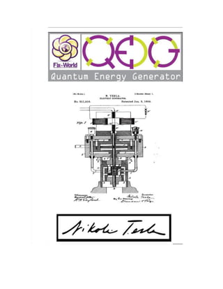
  • 2. QEG SYSTEM DESCRIPTION 3-25-2014 The Quantum Electric Generator system (QEG) is an adaptation of one of Nikola Tesla’s many patented electrical generator / dynamo / alternator designs. The particular patent referenced is No. 511,916, titled simply “Electric Generator”, and dated January 2, 1894 (see back of this manual). The adaptation is a conversion from a linear system, to a rotary system. The QEG prototype is scaled to produce electrical power in the range of 10-15 kW (kilowatts) continuously, and can be set up to provide either 120 Volt or 230-240 Volt single phase output. We are also planning future designs to provide 3-phase power. Service life of the device is limited only by certain replaceable components, such as bearings, v-belts, and capacitors. The basic machine should operate trouble-free (with minimal maintenance) for as long as any good quality electro-mechanical appliance, such as a quality washing machine or refrigerator. Heavy-duty mechanical components are used throughout for reliability. The QEG is not a complicated device, as it is designed (like Tesla’s other ‘discoveries’), to work in harmony with natural laws, rather than with the power-wasting symmetric motor and generator designs used in today’s mainstream industry. An effective way to understand the operating principle of the QEG is to think of it as a high-powered, self- resonant oscillator (a power tank circuit), which generates high-voltage AC (15 to 25kV). These HV oscillations are then transformed into line voltage AC output, at current levels up to approximately 85 A. In today’s alternative energy terminology, it would be called a type of resonance machine. The circuitry that develops high power in this device is really based on an existing but under-utilized power oscillator configuration, however, the ‘quantum’ part of the design has to do with how the generator output is tuned for maximum power. Conventional alternators (AC generators) consume more input power than the output power they provide. For example, one brand of power take off (PTO) alternator uses 18,000 watts (24 horsepower) to develop 13,000 watts of output power. In the QEG, input power is used only to maintain resonance in the core, which uses a small fraction of the output power (under 1000 watts to produce 10,000 watts), and once running, the QEG provides this power to its own 1 horsepower motor. This is known as over- unity. Once the machine builds up to the resonant frequency, it powers itself (self-running). In the QEG, the exciter coil is used to provide a conduction path through the quantum field (zero point) into the generator core. This has the effect of polarizing the core, which increases power output over time. James M. Robitaille
  • 3. NOTICE TO BE READ AND UNDERSTOOD BY ALL QEG PROJECT CREWS Fix the World (FTW) is not responsible for the actions of others. We can only tell you our experience. We have discovered it is essential that those wishing to build a QEG use careful thinking, patience, and consideration for the greater good. The inhabitants of planet Earth are entering into a new paradigm and a new way of doing business. In honor of Nikola Tesla, the QEG is a gift freely given to the world, and FTW’s involvement is strictly altruistic. The QEG is an electromechanical device and as such, safety for the individual and end user should always be of prime concern. It is therefore essential that persons assembling the device are experienced in the field of electro-mechanical assembly. A considerable level of knowledge in quantum physics is also required. IF YOU ARE TRAINED IN TRADITIONAL PHYSICS, AND HAVE NOT BEEN DOING THIS WORK FOR MANY YEARS, YOU MUST FIRST DO YOUR RESEARCH ON BASIC QUANTUM ENERGY DEVICES AND HOW THEY WORK (e.g. resonance and tuning). Electrical / Mechanical devices are inherently dangerous. Electrical shock hazards can cause serious injury and in some cases death. Mechanical hazards can result in dismemberment and in some cases death. Due diligence has been applied to ensure that the QEG instructions are complete and correct. All local and country-specific electrical and mechanical code implications, by which a QEG might be installed and operated, cannot possibly be known. Nor is it conceivable that any and all possible hazards and/or results of each procedure or method have been accounted for. It is for these reasons that the QEG must be either directly installed or supervised by an experienced electromechanical engineer to ensure the installation is done safely and in accordance with local electrical code, however, the QEG is installed the same way as any commercial generator and does not violate any electrical codes. Anyone who uses the QEG installation instructions (including but not limited to any procedure or method of installation) must first satisfy themselves that neither their safety, nor the safety of the end user, will be endangered over the course of the installation and operation of the QEG. It is imperative to understand YOU NEED PROFESSIONALS AND EXPERT ADVICE to build a QEG.
  • 4. The installation instructions are designed to show how we have found the building of the device to be accomplished, and any negative outcomes that result are completely the responsibility of the person/company building it; FTW provides no guarantee for the successful installation of the QEG. This notice serves the purpose of communicating the serious nature of building a quantum machine, as we are well aware that there have been severe restrictive agencies involved with their suppression. Quantum free energy isn’t taught at University and most designers have heretofore been unsuccessful at mass distribution. It is YOUR RESPONSIBILITY therefore to make certain you are building the QEG with positive intentions for humanity, and lashing out legally or otherwise to FTW, HopeGirl and/or the designer and his family, is a violation of goodwill and will in no way be attended to. We know of no other way to do this but to go back to the “HONOR SYSTEM.” In reading this notice I agree that: 1) I WILL NOT ATTEMPT TO BUILD A QEG UNLESS I DO SO APPROPRIATELY WITH AN ELECTROMECHANCIAL ENGINEERING PROFESSIONAL. 2) I WILL NOT COMMISSION (TURN ON) OR INSTALL THE QEG WITHOUT AN ELECTROMECHANICAL ENGINEERING PROFESSIONAL. 3) UNDER THE ABOVE CONDITIONS, I MAY USE THE QEG INSTALLATION INSTRUCTIONS FOR PERSONAL USE, AND UNDERSTAND THE NEED FOR IMPECCABLE COMMITMENT TO THE BETTERMENT OF HUMANITY. IN THE BEST INTEREST OF THE PEOPLE OF PLANET EARTH, I WILL NOT ATTEMPT TO MISUSE OR MONOPOLIZE THE QEG INSTALLATION INSTRUCTIONS IN ANY CAPACITY, NOR WILL I ATTEMPT TO MAKE A HUGE PROFIT AT THE EXPENSE OF ANOTHER HUMAN BEING. IMPORTANT – Please make certain that persons who are to use this equipment thoroughly read and understand these instructions and any additional instructions prior to construction, installation and operation. In addition, we require you to read this notice again when you are ready to assemble the core.
  • 5. Letter from the Editor 3-25-2014 Dear Builder, It is no easy task to build the QEG, and we want to encourage you by offering a short treatise on the importance of ‘consciousness’ in this endeavor. Many are becoming more familiar with Nikola Tesla, his desire for all people to have access to free energy, and his failed attempt to expose this technology to the world. Many have followed him with the same aspirations and, similar to Tesla’s plight, have also been prevented by powers beyond their control. The “free” energy movement is rife with horror stories ranging from government theft of patents, to reputations destroyed, to the murder of untold numbers of brilliant scientists/inventors. We must all consciously and constantly rise above these tyrannical infringements, and create an environment for ourselves and our neighbors, and rediscover Nature’s Laws to be able to live and thrive. We must leave off responding in incredulity to what was “done to us” when we were told and believed we couldn’t create free energy. We are now awake to the point that we know they were lying. Who’s they? The elite for starters – follow the money (watch THRIVE); J.P. Morgan couldn’t put a meter on an energy plan for the world, and so destroyed any chance of that happening through several vicious attacks on Tesla’s reputation and livelihood – basically got Tesla’s ideas out of the way for his own profit and power – and maliciously destroyed the man (youtube: Tesla’s Autobiography). While the electric companies have told the people theirs is the only way to get electricity, and we are dependent on them, the truth is that we have been deprived of this alternative (quantum) energy source for close to 130 years. Morgan’s grip on the energy supply has not loosened one bit in all that time, in fact, you are probably paying more for electricity than ever before, all things being equal. So how do we effect our future now, and free ourselves and the generations to come after us completely from energy tyranny? Building the QEG is one way. It is a journey that requires you think deeply about processes that will, in turn, expand your senses to enable you to receive information from the quantum field of consciousness, or God if you prefer this reference. We believe we had Divine inspiration and help, which began with a burning desire to “get off the grid” and also do something significant for humanity. The timing is wonderful because, as of the writing of this, the entire planet is in turmoil as never before, and people will need to not only be self-sufficient, we will all need to live according to what is good for all (Ubuntu), and help each other for our continued evolution as species/planet. It is with great love that the QEG is offered to the world, and as you take on the task of building one, it is hoped that this becomes your path also: the mission of free energy for all! The next step we ask you to take on your journey, before and during building, is to listen to the discussion here: http://www.youtube.com/watch?v=3FqzTW7qh2U&feature=youtu.be with HopeGirl, Ralph and Marsha Ring, Fernando Vossa and the 3D Global Network. I am, in service to Gaia and its inhabitants, deeply grateful for this technology, and the opportunity to share it! Valerie Robitaille
  • 6. IMPORTANT ADDITIONAL INFORMATION We are not professional writers or photographers and didn’t always have opportunities to document or photograph every step of development. Therefore, please take the level of engineer/electrical experience required to build a QEG very seriously as we are giving these to you under this premise. You will discover the advanced level of knowledge of mechanical/electrical processes needed quickly enough. The correct construction of the QEG requires patience and careful thought. We made several mistakes in development and have given here the steps that were successful. You will probably still make mistakes – and these will be your greatest learning opportunities as you gain more knowledge about this type of energy. Before beginning to build, consider how much you would like to outsource to one of the cottage industry community units (CICUs) near you! In the US we recommend Polaris for the steel stator/rotor construction, and Torelco for toroidal winding. As FTW continues to roll out the distribution plan, and more connections across the world are made, we think CICUs will be commonplace and hence, QEG parts accessible (many people will be making them!) When website URLs were available we provided links for the person reading this online. You may certainly use your own sources for materials but it is imperative you do not alter the instructions/parts herein if you are building a QEG. (We know with increased knowledge you will discover many applications for this technology.) When photographs can be shown to help you visualize a process, they are provided. Please remember, we are not professional manual writers. What we offer you here is free of charge and our gift to humanity – but it comes with great responsibility. Learn as much as you can, use discernment and wisdom, share freely, and you will be privileged to know the secrets of energy creation from the quantum field. We would like to dedicate the success we’ve experienced to our first teacher, Sir Timothy Thrapp, and WITTS Ministries, without whose guidance none of this would be available so soon. We acknowledge and honor the work WITTS has done for over 200 years bringing technology forward, and hope that you will consider making a donation to the ministry for their great work. We would also like to thank our greatest teacher and fellow humanitarian, Nikola Tesla. It is our most gratifying honor to present modern plans for a quantum energy generator to the world, based on Tesla’s discoveries, especially at a time when we the people are being manipulated and controlled by a corrupt energy economy. Tesla wanted everyone on the planet to have energy. We continue to carry out his vision.
  • 8. Parts List Part Type, Model # or MFG PN Quantity Capacitors Ceramic Disc Capacitors 15pF 3150volts 2 Film Capacitors 2.5uF 2000V 12 End Plates and Shrouds Fiberglass reinforced epoxy laminate (for 2 end plates) G10/FR4 (1) sheet ½ inch thick by 3 feet by 4 feet Fiberglass reinforced epoxy laminate (shrouds) G10/FR4 (2) 1/8” x 5.875” diameter Exciter Coil Clear Cast Acrylic Tube 4-3/4” OD x 4-1/2” ID, 1’ Length 1 #10 Magnet wire (see generator core) V-Belts and Pulleys Goodyear 4L430 V-Belt GDYR_4L430 1 1 Groove, 3” x 7/8” bore, type A Pulley (Motor) AK30 x 7/8 1 1 Groove 2.50” Pulley 7/8” bore type A (Generator) AK25X7/8 1 Drive Motor DC PM Variable Speed, 2500 RPM, 180V armature, 7/8” shaft, with base 1 Generator Core Spacer Blocks 1-1/2” x 1-1/2” x 4-1/2” Aluminum 6061-T6 16 Mica Tape 1.00” x 50YD MICA77956X1X50 1 Bonder for shaft/rotor LOCTITE 648 1 7387 Activator (use with bonder) 1.75oz Mica Plate NEMA 6 36” x 36” x .030 1 7/8” Three Bolt Flange Bearings SATRD205-14G 2 Magnet Wire #10 Round HPT or HAPT ~620’ Magnet Wire #20 Round Pulse Shield HTAIHSD 6” SPL/060-Heavy MW35, 73, 36 ~5200’
  • 9. Teflon tubing TFT20019 NA005 (Alpha Wire) 8 pieces (12” each) Fiberglass sleeving w/PVC for #10 HAPT wire (tubing) PF1308 8 pieces (12” each) Tape, white, 1”fiberglass, hi- temp (outer wrap) RG48 (Intertape) 2 rolls Tape, black, 1” reinforced, high-strength 60020719 (Von Roll) 2 rolls Nomex Corner Insulation Torelco 16 Shafting 7/8” dia. x 11.0” long w/standard 3/16” x 3/32” keyway C1045 TGP Trukey 7/8” dia. x 11” 8 inch Bolts, ¼ - 28 thread, Grade 8 1050095555 (Instock Fasteners) 8 Electrical Terminals Assorted ring, spade, and quick connect terminals Additional Parts Variac, 120/240V in, 0-280V out, 9.5 Amps Type 1520 (STACO) 1 Console Box w/panel 1456FG4BKBU (Hammond Mfg.) 1 Plexiglass sheet for mounting 2.5uF capacitors ¼ inch thick by 12 inches sq. 1 Electrical box 4” x 4” 1 50 amp plug 1 50 amp receptacle 1 Switch, start/run DPDT center off, 15 amp, 240V 1 Bridge Rectifier 600 volt, 25 Amp., quick connect terminals 1 Nuts ¼ - 28 Grade 8 8 Washers ¼ “ flat 16 Frame and Base Angle aluminum 1 ½” x 1 ½” x 4 feet. 1/8” thk. 1
  • 10. Suppliers and Parts/Service List POLARIS LASER LAMINATIONS – Generator Core; Rotor TORELCO – Toroidal winding service and complete core processing ready to ship FASTENAL – Retaining (bonding) compound (Loctite 648: bonds rotor to shaft) with activator EIS – Mica tape; 20 gauge Magnet wire S & W – 10 gauge Magnet wire INDUSTRIAL SENSORS AND CONTROLS (ebay) – Motor controller KBIC-240D variable speed DC motor controller; Resistor MOUSER – Capacitors, Enclosures, Variac, Rectifiers, Start/Run switch JDS (ebay) – V belt; pulleys EMCO PLASTICS – End plates ASHEVILLE-SCHOONMAKER MICA – Mica plates DISCOUNT STEEL – Aluminum squares (spacers) BRIGHTON BEST – 8 in. bolts MCMASTER-CARR – Clear acrylic tube for exciter coil LAKE CITY ELECTRIC (ebay) – Variable speed DC Motor (1 hp) THE BIG BEARING STORE – 7/8” Three Bolt Flange Bearing w/set screws Additional Parts High-temperature fiberglass tape (outer wrap) 4” x 4”electrical box 50 amp plug 50 amp receptacle Black fiberglass sleeving (pvc-coated) Black mylar insulating tape Wood or welded steel tubular frame for base 12 - TPC Thomson / AVX Medium Power Film Capacitors Angle aluminum Start/run switch
  • 11. MAJOR GENERATOR COMPONENTS  Stator  Rotor  Bearings  V belts  Capacitors  External exciter coil  End panels/plates  Magnet wire  Drive motor  Control box  Frame and packaging  Variac  Inverter  Pulleys
  • 12. THE STATOR, or generator core, is made using 140 laminations of 24 gauge M19 C5 electrical steel forming a stack of 3 - ½ inches, with a 4 pole configuration. Corresponding ROTOR with 2 poles. Both STATOR and ROTOR are tig welded in 4 places.
  • 13. Shaft
  • 14. Shaft cont’d* * We didn’t use the splines, rather, we used Loctite 648 retaining compound to bond the rotor to the shaft. This technique works very well with a close slip fit between the parts.
  • 15. End Plates Fiberglass reinforced epoxy laminate (FR-4/G10) is used for end plate construction. End plates must be constructed of insulating material, but must also be structurally strong as they support all generator components, including bearings, shaft, rotor and stator. FR4 is the same material used to make circuit boards and is very strong, machinable, and dimensionally stable. Dimensions: End Plates: .500” Thk. G10/FR-4 15” X 16.5” with 15” radius and 2.450” center hole. Bearings The bearings should have a narrow inner ring with set screws for attaching to the shaft. Housing is cast iron with a grease zerk for re-lubing the bearing. We used a 3-bolt flange type mount, but 2-hole or 4- hole can also be used. Bearings are mounted on the inside of the end plates toward the rotor. Capacitors The capacitors are a critical part of the system. The initial configuration on our prototype uses 12 caps, 2.5uF (microfarad) each. Each cap is rated for 2000V. These capacitors are wired in series in order to be able to withstand up to 25,000V in the primary circuit. The value and quantity of these capacitors will be adjusted to tune the frequency of the generator.
  • 16. Variac The variac is used to control the drive motor speed which effectively controls the system power. It’s used during construction/tuning, and prior to self-running set-up when it can be replaced with the smaller, lighter electronic motor drive circuit board. Drive motor control circuit board The drive motor control circuit board is an industry standard SCR type DC motor drive manufactured by KB Electronics. The control board can be mounted in the console box we have included in the parts list, and is provided with a speed control potentiometer for adjusting motor speed. End Plate Layout We used the bare core as a template to drill all the core mounting holes in the proper locations on the end plates. After end plates are cut and finished, place one on a flat work surface that will support 100 lbs. Place the bare core over end plate, aligning the center bore of the core with the center hole in the end plate. Make sure the pole pieces are right to the edge of the radius at the top of the end plate. We used an extra long drill bit to drill the 8 mounting holes. Repeat this process for the other end plate. Alternately, a long pin could be used as a center punch to mark hole locations and drill the holes using a drill press. If using the core as a template be sure to make assembly marks on the core and the end plate so that final assembly will have all the parts in the same orientation and the mounting bolts will go through without binding. Be sure to mark the in-facing and out-facing sides of each panel.
  • 17. CORE ASSEMBLY This is the time to review the NOTICE and section on consciousness at the beginning. We highly recommend ordering your generator set (stator and rotor) from an experienced professional lamination house. When your stator/rotor is welded and drilled, you are ready to bolt down the 8 spacers and wrap the core with 2 types of tape: Wrap 2 layers mica tape around the steel core (round part) followed by 1 layer of 1” reinforced, high-strength black tape. These 3 layers will bring the thickness needed for insulation to 17 mil (be very mindful at the corners of the pole pieces making certain there is no opening in the insulation for the wire to fall down into contact with the steel. If this happens, the coil will be short-circuited). Mica Plate Cuts (16 pieces)
  • 18. Installing Mica Plates After you’ve cut 16 c-shaped mica plates, install them on the top and bottom of each pole piece (front and back). We used a small amount of contact cement to hold them in place for the rest of the processing, but they can also be taped in place with the reinforced black mylar tape. These are installed after core taping and before winding. Wiring You will need to commission a toroidal winding service. They might agree to process the entire core if you supply the materials (mica tapes and plates, corner insulation, aluminum spacers, bolts, outer taping, etc.). Proper winding is critical. Teflon sleeving is installed on the first complete turn of each winding of the #20 wire, and fiberglass/PVC sleeving on the #10 wire. Two coils of 3100 turns each of #20 wire are wound o’n opposing sides (left and right), and 2 coils of 350 turns each of #10 wire on the other sides (top and bottom). Leave about 3 feet of wire at the start of each winding and also at the finish for lead wires. Use enough sleeving to make sure the lead wires are completely insulated where they come through the back end panel. Be sure to secure the finish leads of each coil so that they don’t unravel during handling. Outer Wrap Taping Wrap a single layer of 1” white fiberglass tape tightly and securely around each coil making sure that all wire is covered and tape is butted up against the 4 pole pieces. Generator Assembly Steps Rotor/Shaft/Shroud Assembly Drawings are provided for the shaft showing an optional spline operation that can be used to mount the rotor to the shaft, if desired. We used Loctite 648 industrial adhesive (with activator), which is effective with close fitting parts. Drill a 7/8” center hole, and two ¼” mounting holes into the shroud disks (mounting holes are lined up with the holes in the rotor). Slide one disk onto the shaft on each side of the rotor. Bolt both shrouds to the rotor using two 4” or 4-1/4” long ¼ - 28 through-bolts and nuts. These bolts should not be any
  • 19. longer than necessary or a rotor imbalance can occur. Shrouds are used to quiet the windage noise generated by the spinning rotor. Bearings Mount bearings to the inside of the front and rear end plates. Center each bearing on the 2.450” hole in the center of the plate. Drill the holes oversize for the mounting bolts. This is done to provide adjustability in the position of the shaft at final assembly. The bearings will have to be moved slightly to center the rotor in the bore of the generator. The gap between rotor and stator is very small (.010”) and the rotor will need to be positioned so it does not rub on the stator bore. Only tighten finger tight at this time. We opted to bring the leads from the coils out directly through holes drilled in the rear end plate. You may decide to bring the leads out a different way. Here are the steps for our method: 1) Insert all 8 bolts into the rear end plate, then lay the plate down on a flat work surface with the bolts pointing up. The work surface should have a hole under the center hole in the end plate to provide clearance when the rotor is inserted. About 1 ½ inches of clearance is needed below the plate. 2) With an assistant or two, place the fully processed core (about 90 lbs.) down onto the bolts. Slide the core all the way down into contact with the end plate. 3) Insert the short end of the rotor/shaft/shroud assembly through the stator bore and into the rear bearing. Let the rotor assembly drop gently to the bottom and place the front end plate with bearing over the bolts and shaft end. Tap into place with rubber mallet if necessary. Once plate is in contact with stator assembly, install washers and nuts and tighten securely. 4) With assistance, place the assembly upright onto the raised portion of the base. We used 5 lag bolts across the bottom of the end plates on each side to mount the assembly to the wood base/frame. Other methods could be employed. 5) Mount the drive motor to the base/frame. We mounted the shaft end of the motor onto the aluminum angle on the front of the base with one bolt to provide adjustability for belt tightening. We built a sliding mount for the rear of the motor using sheet metal parts, but sliding motor bases are commercially available that provide adjustability for proper belt tensioning. 6) When the motor is mounted to the base, install 3” pulley on motor shaft using set screws. 7) At this point the rotor position should be adjusted so that it spins freely inside the core without rubbing. This is where you may need to adjust the bearing positions repeatedly until the rotor spins freely. (The gap between the rotor and stator is .010” making this step a little delicate.) however, once the rotor is tightened in position it does not tend to move. Place the 2 ½” pulley on the generator shaft at this time; it can be used to turn the rotor by hand while adjusting its position.
  • 20. 8) Place the V-belt over both pulleys and position pulleys as close to the motor and the generator as possible. Both pulleys should be positioned an equal distance from the faces of the motor and generator to assure that the belt runs true. 9) The variac can be mounted on the base at this time. We used two 1/4 – 20 x 1” bolts with nuts to mount the variac to the aluminum angle. After all the components are mounted on the base, wiring and testing will be performed using the variac. (After set-up and testing is completed, the variac can be replaced with the electronic motor control circuit board for less bulk and weight. The console box in the parts list can be used as an enclosure/control panel for the motor speed control board, and for mounting the DPDT start/run switch.) 10) With all components mounted on the base, wiring can begin. Please follow the schematic to make connections. We mounted a 4” x 4” electrical box on the base to support a large (50 Amp) receptacle to bring the power out of the generator. Wiring Notes: The generator output can be wired in series (220, 230-240V), or parallel (110, 115, 120V). For the series connection shown on the schematic, the start leads from each coil are connected together. This connection provides the highest voltage output from the windings. If using a parallel connection for lower voltage/higher current, be careful to connect the four leads with polarity opposed (start lead of one coil connected to finish lead of other coil). The variac we used can be wired for 120 or 240 volt input, and provides 0-280 volts output, at up to 9.5 amps. This is a versatile variac and can be used with either a 120 or 240 volt system. The output of the variac is connected to a 600 volt, 25 Amp full-wave bridge rectifier to power the variable speed DC drive motor. Set-up and testing Starting with the wiring setup as shown in the schematic, disconnect the primary coils from the series capacitor string on one end (disconnect capacitors). This will prevent resonance momentarily. Connect input power to the variac. We started with a full 240 volt series wired system, but parallel 120 volt wiring can also be used. Test mechanical assembly by spinning up the motor/rotor/belt and observing operation. Adjust variac voltage from zero to about ¾ through its range. The active rpm range is under 2500 rpm, so we don’t need to spin very fast. Assure there is no stack rub (rotor scrubbing on stator), or other mechanical issues that need to be corrected for smooth operation.
  • 21. When proper mechanical operation is assured, re-connect the series capacitor bank. The initial configuration of 12 (twelve) 2.5 uF, 2000 volt capacitors gives us .208uF, that will withstand up to 24,000 volts. This initial value should be in the range to produce resonance. As the machine spins up to resonance, the sound will change, and the rotor speed will lock into the resonant frequency. At this point any further increase of the motor speed control will change the speed only slightly, but the additional mechanical power (horsepower) will drive the core deeper into resonance, thereby increasing the power output. With a single control, the voltage and current (power) can be increased or decreased. As previously mentioned, the exciter coil is used to provide a conduction path through the quantum field (zero point) into the generator core. This has the effect of polarizing the core, which increases power output over time. After the QEG is first built, the spark gap on the exciter coil should be adjusted (with power off) to between .005” and .010”. Start the generator and let it spark for 2-3 seconds, and repeat this 4 or 5 times. Do this whenever starting the generator for the first few weeks of operation.
  • 22.
  • 23.
  • 24.
  • 25.
  • 26.
  • 27.
  • 28.
  • 29.
  • 30.
  • 31.
  • 32.
  • 33.
  • 34.
  • 35. Frequently Asked Questions - Where is the energy this device is using coming from ? The quantum field - How much overall power does the QEG produce? 10 KW (same design scaled up can produce 40 KW) - If ‘free’ energy devices work, why aren’t the electric companies using them? This should be obvious but in case you need a reference, please see: http://hopegirl2012.wordpress.com/ - How is the QEG started up if it doesn’t require fuel? All that’s needed is to spin the machine up to resonance. At that point it will run itself. It can be started using existing electrical power if available, or a crank mechanism, or a battery powered motor-start system. A battery start system could also keep its own batteries fully charged, by tapping some power from the generator. - How long will the QEG run? Indefinitely (or until parts wear out) - How did the QEG improve upon Tesla’s work? This design adapts the linear, reciprocating element of the Patent, to a rotating element, and some electronics are employed for added stability; controlled amount of power and correct frequency range. - Does the QEG slow down when more of a load is added? No – it’s not that type of energy. - Does the QEG emit radiation? No – it’s not that type of energy. - What form of energy does QEG use? Electromagnetic and atmospheric charge