This document discusses the development of a full-bridge pulser using silicon carbide (SiC) MOSFETs for fusion science applications. The pulser is being developed to meet the needs of the fusion community and advance switching power supplies. It will be capable of output voltages up to 2 kV peak-to-peak, currents up to 10 kA peak-to-peak for short pulses and 4 kA for longer pulses, and continuous currents up to 400 A. Testing has shown the pulser operating into resistive and inductive loads at frequencies up to 1 MHz. Future work will include testing into a tank circuit and incorporating enhanced thermal management and fault detection.
Introduction to Electronics design , passing first by intro to electricity then some PCB desigining Hacks . this was part of OSTA LAB internship program in Fablab Egypt . it is the same curriculum needed to pass MIT Fab Academy .
Introduction to Electronics design , passing first by intro to electricity then some PCB desigining Hacks . this was part of OSTA LAB internship program in Fablab Egypt . it is the same curriculum needed to pass MIT Fab Academy .
This is a simple circuit to charge 1.2V, 4600mAh rechargeable Ni-MH battery from a solar panel. This solar charger has current and voltage regulation and also has over voltage cut off facilities. Solar battery charger operates on the principle that the charge control circuit will produce a constant voltage. The charging current passes to LM7805 voltage regulator through the diode D1. The output voltage and current are regulated by adjusting the adjust pin of LM7805 voltage regulator. Battery is charged using the same current.
KEMET Webinar - 0805 and 1206 footprints now available with higher rated volt...Markus Trautz
The "evergreen" application requirement for miniaturization has driven the development of small case size Polymer Capacitors to rated voltage levels of 25V now. In case sizes 0805 (4.7µF/25V) and 1206 (="A Case" footprint with max. height of 1.2 mm, 10µF/25V) customers can now benefit from the stable capacitance with DC voltage applied as well as the usage for application voltages up to 22.5V in case sizes usually known from Multi-Layer Ceramic Capacitors (MLCC´s).
With the MLCC technology undergoing changes towards even smaller case sizes and facing extended lead times, small case size Polymer Capacitors can represent an interesting alternative for your Capacitance requirement.
Electricity can cause serious injury or even death which is why safety must come first when working with electricity or electrical devices. In order to avoid injury, prior to starting work on an electrical box such as an AC mains switch-board or a power supply, for example, you must first verify there is no AC voltage. If you can't completely isolate your device from the supply wires, how can you be sure that there's no voltage remaining? Enter a non-contact AC voltage detector.
There are several options available on the market and they range in price, but in true DIY fashion, with this kit, you are able to quickly and easily create your own non-contact AC voltage detector in less than an hour.
Inductive shielded superconducting fault current limiter: test results for sc...Franco Moriconi
Results of measurements with a downscaled model of a novel superconducting inductive Shielded Fault Current Limiter (iSFCL) based on 2nd generation HTS material are reported. Two different types of models were tested, one with an open iron core and one with a closed iron core. The operational characteristics of both systems with focus on the superconducting secondary modules in normal operation and in quenching mode with quench times of up to 500 ms are analyzed. The HTS modules are based on 40 mm wide YBCO coated conductors with a high-ohmic protection layer and an external shunt system. Further development/testing program includes a 3-phase-field trial, where a full scale technology demonstrator (15-MVA class) will be integrated in the distribution grid of the utility Stadtwerke Augsburg in Germany. This joint project of Schneider Electric, Bruker HTS, Bruker Advanced Supercon and Stadtwerke Augsburg is supported by the German Federal Ministry of Economics and Technology (BMWi)
Supercapacitors or EDLCs (i.e. electric double-layer capacitors) or ultra-capacitors are becoming increasingly popular as alternatives for the conventional and traditional battery sources. This brief overview focuses on the different types of supercapacitors, the relevant quantitative modeling areas and the future of supercapacitor research and development. Supercapacitors may emerge as the solution for many application-specific power systems. Especially, there has been great interest in developing supercapacitors for electric vehicle hybrid power systems, pulse power applications, as well as back-up and emergency power supplies. Because of their flexibility, however, supercapacitors can be adapted to serve in roles for which electrochemical batteries are not as well suited. Also, supercapacitors have some intrinsic characteristics that make them ideally suited to specialized roles and applications that complement the strengths of batteries. In particular, supercapacitors have great potential for applications that require a combination of high power, short charging time, high cycling stability and long shelf life. So, let’s just begin the innovative journey of these near future of life-long batteries that can charge up almost anything and everything within a few seconds!
these slide are dedicated to constructing travelling mobile charge using just 2 or 4 pencil cells . very useful for travelling purpose with a simple circuit diagram.
Syntech Electromech Private Limited is an independent, fast-growing engineering group
offering wide range of Manufacturing Solution & Technical services in the field of Power,
Energy, Power System Studies, Design, Erection, Maintenance, Testing & Commissioning of
Electricals.
We have in the form of qualified and experienced Engineers who are involved in the
aforementioned services.
The standard electromechanical RCCBs are designed to work with normal waveform power and cannot be guaranteed to work if any standard waveforms are generated by loads. The most common is the rectified half-wave waveform, sometimes referred to as pulsed direct current, generated by speed control devices, semiconductors, computers, and even dimmers.
“Fast close dank zij aangepaste structuren" bij Agfa Healthcare
Dubbel interview Ann Goossens & Karen Mattheessens
Martin van Wunnik – FD Magazine n°100, December 2015
Impact of gamma-ray irradiation on dynamic characteristics of Si and SiC powe...IJECEIAES
Power electronic devices in spacecraft and military applications requires high radiation tolerant. The semiconductor devices face the issue of device degradation due to their sensitivity to radiation. Power MOSFET is one of the primary components of these power electronic devices because of its capabilities of fast switching speed and low power consumption. These abilities are challenged by ionizing radiation which damages the devices by inducing charge built-up in the sensitive oxide layer of power MOSFET. Radiations degrade the oxides in a power MOSFET through Total Ionization Dose effect mechanism that creates defects by generation of excessive electron–hole pairs causing electrical characteristics shifts. This study investigates the impact of gamma ray irradiation on dynamic characteristics of silicon and silicon carbide power MOSFET. The switching speed is limit at the higher doses due to the increase capacitance in power MOSFETs. Thus, the power circuit may operate improper due to the switching speed has changed by increasing or decreasing capacitances in power MOSFETs. These defects are obtained due to the penetration of Cobalt60 gamma ray dose level from 50krad to 600krad. The irradiated devices were evaluated through its shifts in the capacitance-voltage characteristics, results were analyzed and plotted for the both silicon and silicon carbide power MOSFET.
A solar inverter, or PV inverter, converts the direct current (DC) output of a photovoltaic solar panel into a utility frequency alternating current (AC) that can be fed into a commercial electrical grid or used by a local, off-line electrical network.
Characterization and Modeling of Power Electronics DeviceIAES-IJPEDS
During the three decades spent, the advances of high voltage/current semiconductor technology directly affect the power electronics converter technology and its progress. The developments of power semiconductors led successively to the appearance of the elements such as the Thyristors, and become commercially available. The various semiconductor devices can be classified into the way they can be controlled, uncontrolled category such as the Diode when it’s on or off state is controlled by the power circuit, and second category is the fully controlled such as the Metal Oxide Semiconductor Field Effect Transistor (MOSFET), and this category can be included a new hybrid devices such as the Insulated Gate Bipolar Transistor (IGBT), and the Gate Turn-off Thyristor (GTO). This paper describes the characteristics and modeling of several types of power semiconductor devices such as MOSFET, IGBT and GTO.
Towards More Reliable Renewable Power Systems - Thermal Performance Evaluatio...IJPEDS-IAES
Power electronic converters (PECs) are one of the most important elements
within renewable power generation systems. The reliability of switching
elements of PECs is still below expectations and is a major contributor to the
downtime of renewable power generation systems. Conventional technology
based elements such as Silicon Insulated Gate Bipolar Transistors (IGBTs)
operate as switching components in PECs. Recent topological improvements
have led to new devices called Silicon Carbide (SiC) MOSFETs which, are
also being used as switching elements for PECs. This paper presents detailed
investigations into the performance of those switching devices with a focus
on their reliability and thermal characteristics. Namely, trench gate NPT, FS
IGBT topologies and SiC MOSFET are firstly modelled using 3-D multiphysics
finite element modelling to gain clear understanding of their thermal
behaviour. Subsequently, modelling outcomes are verified by using those
devices as switching elements in operational boost converters. The
purposely-developed test setups are utilised to critically assess the
performances of those switching devices under different loading and
environmental conditions. In general, SiC device was found to exhibit about
20 °C less in its operating temperature and therefore expected to offer more
reliable switching element.
Saturated core fault current limiter field experience at a distribution subst...Franco Moriconi
Zenergy Power has been developing an inductive-type of
fault current limiter (FCL) for electric power grid
applications. In March 2009 Zenergy Power installed a
FCL in the Avanti distribution circuit of Southern
California Edison’s Shandin substation in San Bernardino,
CA, rated at 15 kV and 1,200 amperes steady-state. In
January 2010, this device successfully limited its first series
of real-world faults when the circuit experienced multiple
single-phase and three-phase faults. Zenergy Power also
received contracts to deliver an 11 kV, 1,250 amperes FCL
for the CE Electric UK grid and a 138 kV, 1,300 amperes
FCL for the Tidd substation of American Electric Power.
1. T. M. Ziemba; K. E. Miller; J. R. Prager; J. Picard; and A. Hashim
ziemba@eagleharbortech.com
Introduction:
A current challenge facing the fusion energy community is the ability to
generate increased pulsed power levels at low cost and in a robust manner.
During the past decade, the state of the art in power semiconductors has
advanced significantly. The introduction of silicon carbide (SiC)
semiconductor devices provides advantages of fast, high-temperature and/or
high-voltage devices. In 2011, Cree, Inc. introduced the first 1200 V SiC
metal–oxide–semiconductor field-effect transistor (MOSFET) into the
commercial market. Since the initial introduction, other MOSFET
manufacturers, including ST Microelectronics, Microsemi, and POWEREX,
have introduced a SiC line of MOSFETs. In order to meet the needs of the
fusion science community and advance the state-of-the-art in switching
power supplies and pulsers, Eagle Harbor Technologies, Inc. (EHT) is
developing a full-bridge pulser, which takes advantage of SiC MOSFETs.
This full-bridge can be operated CW or in pulsed applications and will be
tested on the HIT experiment at the University of Washington.
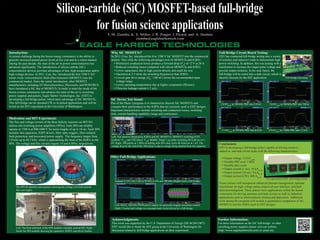
Silicon-carbide (SiC) MOSFET-based full-bridge
for fusion science applications
Conclusions
EHT is developing a full-bridge pulser capable of driving resistive,
inductive, and tank circuit loads with the following characteristics:
• Output voltage: 2.0 kVpk-pk
• Variable PRF over 1 MHz
• Variable duty cycle
• Output current (1 ms): 10 kApk-pk
• Output current (10 ms): 4 kApk-pk
• Output current (CW): 400 Apk-pk
Future pulsers will incorporate enhanced thermal management, optional
transformer for high voltage pulses,improved user interface, and fault
detection/mitigation. These pulsers have applications within the fusion
community for driving antennas and tank circuits as well as industrial
applications such as semiconductor etching and deposition. Additional
work during this program will include a quantitative comparison of SiC
MOSFETs and the IGBTs used in EHT designs.
Acknowledgments:
This work was supported by the U.S. Department of Energy (DE-SC0011907).
EHT would like to thank the HIT group at the University of Washington for
discussion related to full-bridge applications on their experiment.
Full-Bridge Circuit Board Testing:
EHT has conducted full-bridge testing into a variety
of resistive and inductive loads to demonstrate high
power switching. In addition, this was testing with a
transformer to increase the output pulse voltage and
provide output isolation. In the near future, the
full-bridge will be tested into a tank circuit, which is
directly relevant for the HIT application.
Further Information:
For more information on the SiC full-bridge or other
switching power supplies please visit our website
(http://www.eagleharbortech.com) or email me.
SiC Device Test Stand:
Part of the Phase I program is to characterize discrete SiC MOSFETs and
compare their performance to the IGBTs that are currently used in EHT designs.
Important characteristics include switching and conduction losses, switching
time, current handling capability (surge and continuous).
Left: Test stand to characterize IGBTs and SiC MOSFETs. MOSFET switching (CH1
(yellow): Vload
and CH2 (blue): VDS
). Middle: Single 1 μs pulse switching 40 A/device at 1
kV. Right: 100 pulses at 1 MHz switching with 50% duty cycle 40 A/device at 1 kV. The
voltage drop by the end of the 100 pulses is due to energy being drained from the capacitor
Motivation and HIT Experiment:
The flux and voltage circuits of the three helicity injectors on HIT-SI3
utilizes old switching power amplifiers (SPAs). Each SPA can reliably
operate at 1500 A at 900-1000 V for pulse lengths of up to 10 ms. Each SPA
includes fast capacitors, IGBT drivers, fiber optic triggers, fiber-isolated
fault protection, and associated power supply. The frequency ranges from
5.8 kHz up to 68.5 kHz, which is approaching the limit of the IGBTs in the
SPA. The voltage and flux circuits require 14 and 6 SPAs, respectively.
Other Full-Bridge Applications:
Left: The front and back of the SPA modules currently used at HIT. Right:
Inside the SPA module showing the capacitors, IGBTs, and driver boards.
The HIT-SI chamber and injectors showing the voltage coil (left) and the
flux coil (right).
Isolated 2.5 kV into 2 kΩ at 50 kHz (Left) and 100 kHz (Right) from a full-bridge.
Left: 40 kA, 100 kHz PWM power supply for precision magnet waveform control.
Right: Current and voltage in a resonant tank circuit driven by a full-bridge.
Why SiC MOSFETs?
In 2011, Cree, Inc. introduced the first 1200 V SiC MOSFET into the commercial
market. They offer the following advantages over Si MOSFETs and IGBTs:
• Minimized conduction losses produce a forward drop (VF
) of <2 V at 20 A.
• Reduced switching losses compared with silicon MOSFETs and IGBTs.
• Lower capacitance due to high current density and small die size.
• Operation at 2-5 times the switching frequencies than IGBTs.
• Lowest gate drive energy (QG
<100 nC) across the recommended input
voltage range.
• Lower operating temperatures due to higher component efficiency.
• Ultra-low leakage current (<1 µA).
First generation EHT full-bridge pulser.
2.0 kVpk-pk
at 1 MHz PRF into 3.2 kA.
1.8 kVpk-pk
at 100 kHz PRF into 2.9 kA. 1.8 kVpk-pk
at 100 kHz PRF into 720 A.
Full-bridge test setup.
1.5 kVpk-pk
at 500 kHz PRF into 8.0 kA