Download as PDF, PPTX


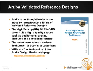
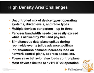
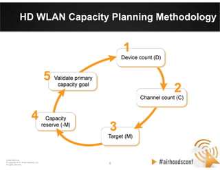
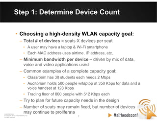
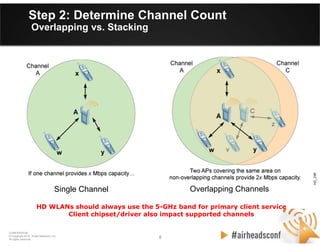
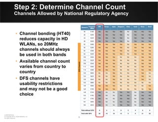


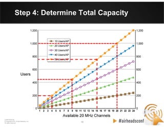

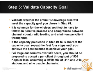

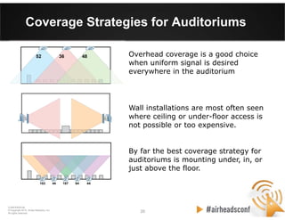
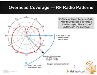
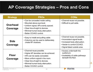

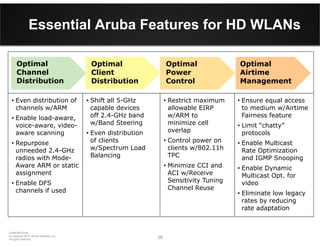


The document discusses capacity planning and radio frequency design recommendations for high-density wireless local area networks provided in Aruba's Validated Reference Design guide. It covers topics such as determining device count and channel requirements, choosing target concurrent user levels, and validating the capacity goal. The guide also examines coverage strategies like overhead, floor, and side-mounting of access points and essential Aruba features to optimize airtime management and channel distribution for high-density environments.


