Downloaded 100 times


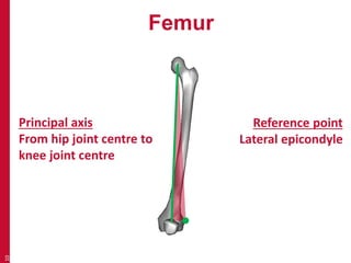
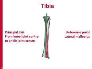
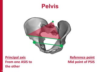
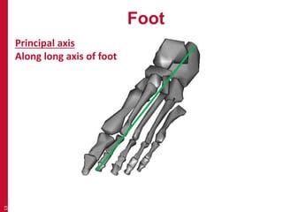


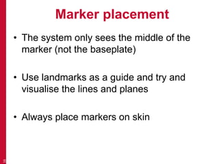
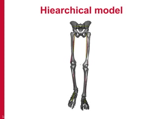
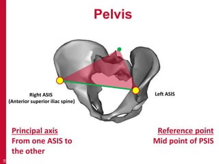
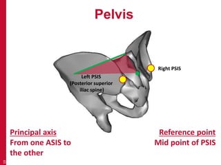
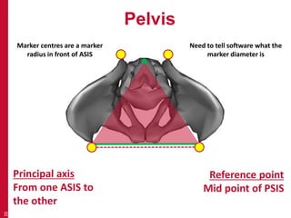
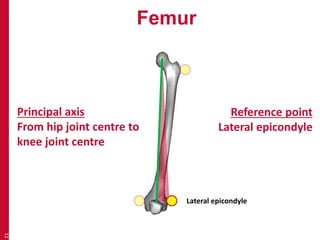
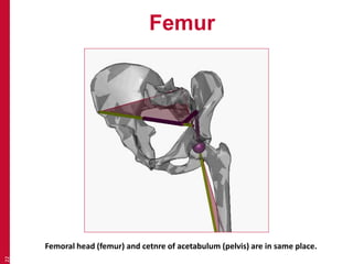
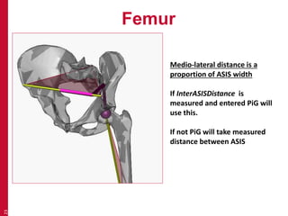
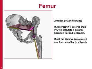

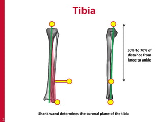
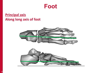
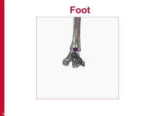
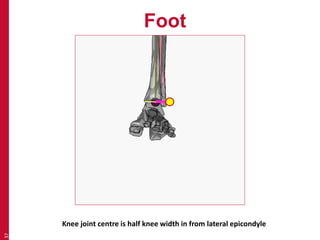
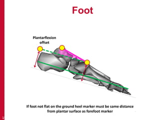

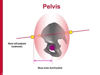
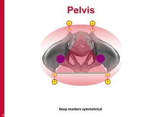
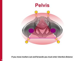


This document provides an introduction to the conventional gait model used in clinical gait analysis. It discusses the key aspects of the model including the anatomical segment definitions for the pelvis, femur, tibia, and foot. Marker placement for each segment is described, highlighting the importance of placing markers over bony landmarks to define segment axes and reference points according to the model. Challenges of applying the model to individuals with anatomical variations are also addressed.


