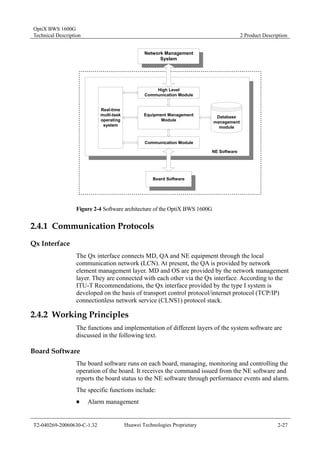
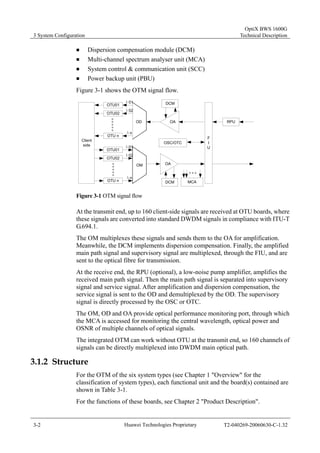
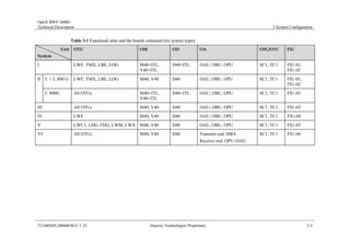
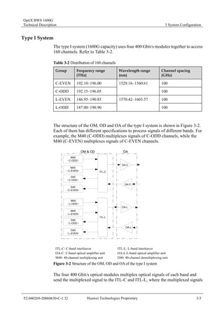
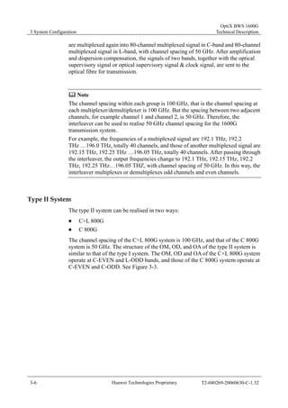
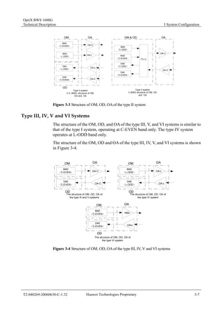
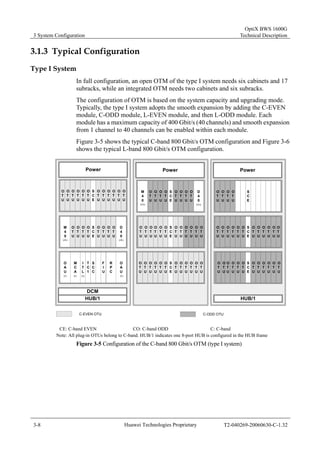
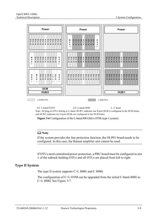
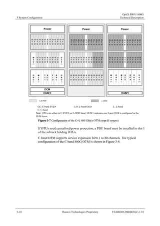
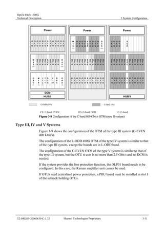
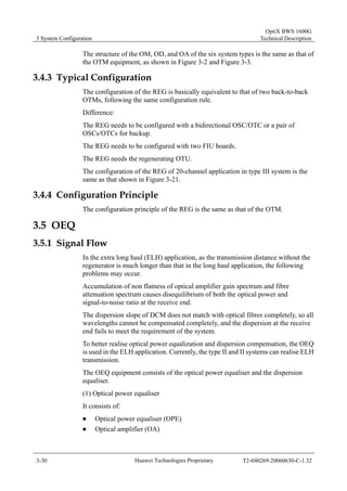
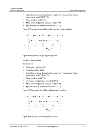
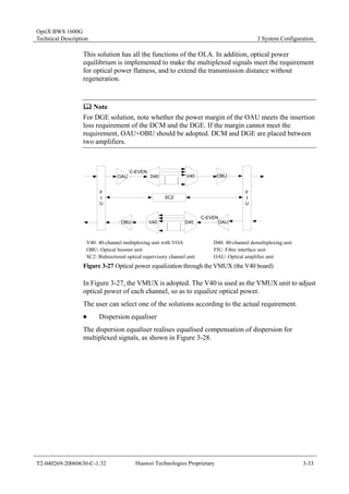
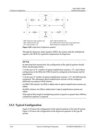
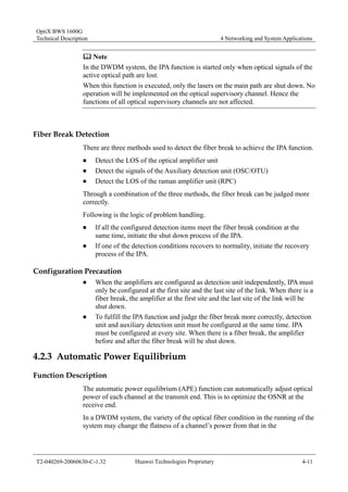
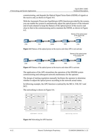
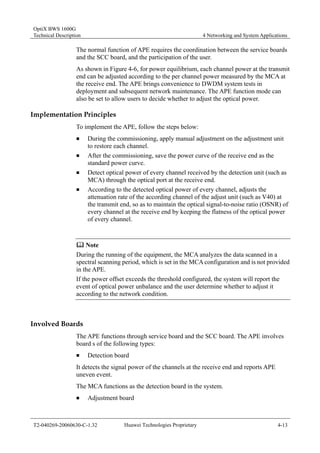
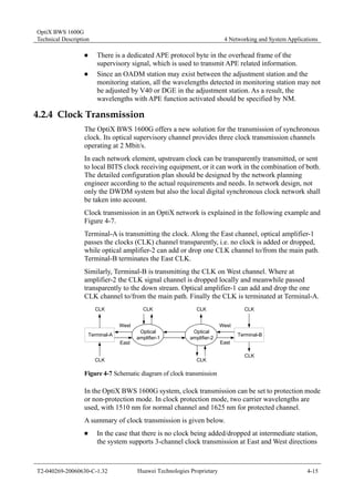
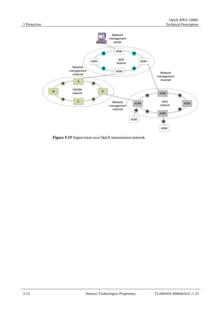
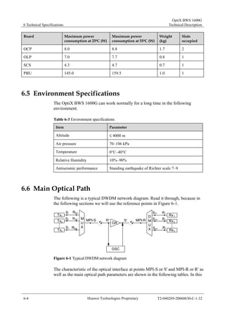
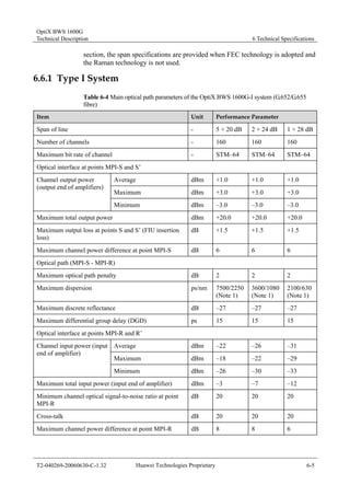
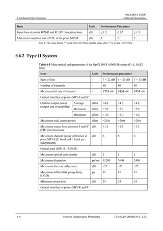
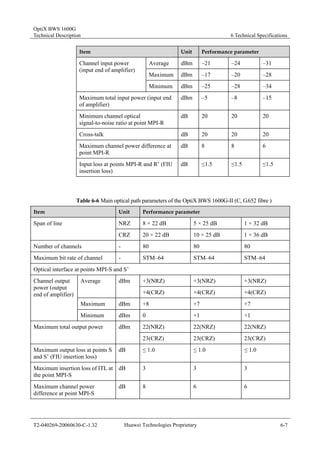
1 Overview........................................................................................................ 1-1 
1.1 Introduction to the OptiX BWS 1600G.................................................... 1-1 
1.2 Types of the OptiX BWS 1600G............................................................. 1-4 
1.3 Features ................................................................................................. 1-7 
1.4 Characteristics........................................................................................ 1-9 
1.4.1 Service Characteristics .................................................................. 1-9 
1.4.2 Technical Characteristics............................................................... 1-9 
1.4.3 Intelligent Adjustment..................................................................... 1-11 
1.4.4 Automatic Monitoring ..................................................................... 1-11 
1.4.5 Reliabilty ........................................................................................ 1-12 
1.5 Network Management System............................................................... 1-13 
2 Product Description ..................................................................................... 2-1 
2.1 Cabinet ................................................................................................... 2-1 
2.1.1 Overview........................................................................................ 2-1 
2.1.2 Specifications................................................................................. 2-2 
2.2 Subrack .................................................................................................. 2-3 
2.2.1 Structure ........................................................................................ 2-3 
2.2.2 Specifications................................................................................. 2-4 
2.3 Functional Units...................................................................................... 2-5 
2.3.1 Optical Transponder Unit ............................................................... 2-9 
2.3.2 Optical Multiplexer/Demultiplexer and Add/Drop Multiplexer......... 2-16 
2.3.3 Optical Amplifier ............................................................................. 2-18 
2.3.4 Optical Supervisory Channel and Timing Transporting Unit .......... 2-21 
2.3.5 Performance Monitoring and Adjustment Unit ............................... 2-22 
2.3.6 Optical Fibre Automatic Monitoring Unit ........................................ 2-23 
2.3.7 Protection Unit ............................................................................... 2-24 
2.3.8 System Control and Communication Unit ...................................... 2-25 
2.4 System Software Architecture ................................................................ 2-26 
2.4.1 Communication Protocols .............................................................. 2-27 
2.4.2 Working Principles ......................................................................... 2-27 
3 System Configuration .................................................................................. 3-1 
3.1 OTM ....................................................................................................... 3-1 
3.1.1 Signal Flow .................................................................................... 3-1 
3.1.2 Structure ........................................................................................ 3-2 
3.1.3 Typical Configuration ..................................................................... 3-8 
3.1.4 Configuration Principle................................................................... 3-13 
3.2 OLA ........................................................................................................ 3-15 
3.2.1 Signal Flow .................................................................................... 3-15 
3.2.2 Structure ........................................................................................ 3-16
3.2.3 Typical Configuration ..................................................................... 3-17 
3.2.4 Configuration Principle................................................................... 3-19 
3.3 OADM..................................................................................................... 3-20 
3.3.1 Signal Flow .................................................................................... 3-20 
3.3.2 Structure ........................................................................................ 3-24 
3.3.3 Typical Configuration ..................................................................... 3-26 
3.3.4 Configuration Principle................................................................... 3-28 
3.4 REG........................................................................................................ 3-29 
3.4.1 Signal Flow .................................................................................... 3-29 
3.4.2 Structure ........................................................................................ 3-29 
3.4.3 Typical Configuration ..................................................................... 3-30 
3.4.4 Configuration Principle................................................................... 3-30 
3.5 OEQ ....................................................................................................... 3-30 
3.5.1 Signal Flow .................................................................................... 3-30 
3.5.2 Structure ........................................................................................ 3-32 
3.5.3 Typical Configuration ..................................................................... 3-34 
3.5.4 Configuration Principle................................................................... 3-36 
4 Networking and System Applications ........................................................ 4-1 
4.1 Networking and Applications .................................................................. 4-1 
4.1.1 Type I system................................................................................. 4-3 
4.1.2 Type II system................................................................................ 4-3 
4.1.3 Type III system............................................................................... 4-4 
4.1.4 Type IV system.............................................................................. 4-6 
4.1.5 Type V system ............................................................................... 4-6 
4.1.6 Type VI system.............................................................................. 4-6 
4.2 System Functions ................................................................................... 4-8 
4.2.1 Automatic Level Control ................................................................. 4-8 
4.2.2 Intelligent Power Adjustment ......................................................... 4-10 
4.2.3 Automatic Power Equilibrium......................................................... 4-11 
4.2.4 Clock Transmission........................................................................ 4-15 
4.2.5 Optical Fiber Line Automatic Monitoring ........................................ 4-16 
5 Protection...................................................................................................... 5-1 
5.1 Power protection .................................................................................... 5-1 
5.1.1 DC Input Protection........................................................................ 5-1 
5.1.2 Secondary Power Protection ......................................................... 5-1 
5.1.3 Centralised Power Protection for OTUs ......................................... 5-1 
5.2 Service Protection .................................................................................. 5-2 
5.2.1 1+1 Line Protection........................................................................ 5-2 
5.2.2 Optical Channel Protection ............................................................ 5-2
5.3 Clock Protection ..................................................................................... 5-7 
5.4 Network Management Channel .............................................................. 5-10 
5.4.1 Protection of Network Management Information Channel ............. 5-10 
5.4.2 Interconnection of Network Management Channel........................ 5-11 
6 Technical Specifications.............................................................................. 6-1 
6.1 Optical Interfaces ................................................................................... 6-1 
6.2 Power Supply ......................................................................................... 6-1 
6.3 Parameters of Mechanical Structure...................................................... 6-2 
6.4 Nominal Power Consumption, Weight and Slots of Boards ................... 6-2 
6.5 Environment Specifications .................................................................... 6-4 
6.6 Main Optical Path ................................................................................... 6-4 
6.6.1 Type I System................................................................................ 6-5 
6.6.2 Type II System............................................................................... 6-6 
6.6.3 Type III System.............................................................................. 6-10 
6.6.4 Type IV System.............................................................................. 6-18 
6.6.5 Type V System............................................................................... 6-19 
6.6.6 Type VI System.............................................................................. 6-20 
6.7 Optical Amplifier ..................................................................................... 6-21 
6.7.1 OAU ............................................................................................... 6-21 
6.7.2 OBU ............................................................................................... 6-25 
6.7.3 OPU ............................................................................................... 6-27 
6.7.4 HBA................................................................................................ 6-28 
6.7.5 Raman Amplifier ............................................................................ 6-29 
6.8 Optical Transponder Unit (OTU) ............................................................ 6-30 
6.8.1 Specifications of Client Side Optical Module at 2.5 Gbit/s and 
Lower ...................................................................................................... 6-30 
6.8.2 Specifications of 10 Gbit/s Optical Module at Client Side .............. 6-31 
6.8.3 Specifications of 2.5 Gbit/s Fixed Wavelength Optical Module 
at DWDM Side ........................................................................................ 6-33 
6.8.4 Specifications of 2.5 Gbit/s Tunable Wavelength Optical 
Module at DWDM Side ........................................................................... 6-34 
6.8.5 Specifications of 10 Gbit/s Fixed Wavelength Optical Module at 
DWDM Side ............................................................................................ 6-35 
6.8.6 Specifications of 10 Gbit/s Tunable Wavelength Optical 
Module at the DWDM side ...................................................................... 6-36 
6.8.7 LWF and LWFS ............................................................................. 6-36 
6.8.8 TMX and TMXS ............................................................................. 6-38 
6.8.9 LBE and LBES............................................................................... 6-40 
6.8.10 LOG and LOGS ........................................................................... 6-42 
6.8.11 LWC1 ........................................................................................... 6-42 
6.8.12 LWM and LWMR.......................................................................... 6-44
6.8.13 LWX and LWXR........................................................................... 6-46 
6.8.14 LDG.............................................................................................. 6-48 
6.8.15 FDG ............................................................................................. 6-49 
6.8.16 Jitter Transfer Characteristics ...................................................... 6-50 
6.8.17 Input Jitter Tolerance ................................................................... 6-51 
6.8.18 Jitter Generation .......................................................................... 6-52 
6.9 Optical Multiplexer/Demultiplexer/Add and Drop multiplexer ................. 6-52 
6.9.1 M40 and V40.................................................................................. 6-52 
6.9.2 D40 ................................................................................................ 6-53 
6.9.3 MR2 ............................................................................................... 6-53 
6.9.4 DWC .............................................................................................. 6-54 
6.10 Other Units ........................................................................................... 6-55 
6.10.1 FIU ............................................................................................... 6-55 
6.10.2 ITL................................................................................................ 6-58 
6.10.3 OCP ............................................................................................. 6-58 
6.10.4 OLP.............................................................................................. 6-59 
6.10.5 SCS.............................................................................................. 6-59 
6.10.6 GFU ............................................................................................. 6-59 
6.10.7 DGE ............................................................................................. 6-60 
6.10.8 DSE.............................................................................................. 6-60 
6.10.9 VOA ............................................................................................. 6-61 
6.10.10 VA4 ............................................................................................ 6-61 
6.10.11 MCA........................................................................................... 6-61 
6.10.12 OSC ........................................................................................... 6-62 
6.10.13 FMU ........................................................................................... 6-62 
6.10.14 MWF .......................................................................................... 6-63 
6.10.15 MWA .......................................................................................... 6-63 
6.11 DCM ..................................................................................................... 6-64 
6.12 Channel Allocation ............................................................................... 6-65 
6.13 Electromagnetic Compatibility (EMC)................................................... 6-69 
6.14 Environment Requirement.................................................................... 6-71 
6.14.1 Storage Environment ................................................................... 6-71 
6.14.2 Transport Environment ................................................................ 6-73 
6.14.3 Operation Environment ................................................................ 6-75 
A Measures in DWDM Network Designing .................................................... A-1 
A.1 Dispersion Limited Distance .................................................................. A-1 
A.2 Signal Power.......................................................................................... A-2 
A.3 Optical Signal-to-Noise Ratio................................................................. A-3 
A.4 Other Effects .......................................................................................... A-4
B Technology Introduction ............................................................................. B-1 
B.1 FEC........................................................................................................ B-1 
B.2 SuperWDM ............................................................................................ B-2 
B.3 Raman Amplification.............................................................................. B-3 
C Glossary........................................................................................................ C-1 
D Acronyms and Abbreviations ..................................................................... D-1 
Index .................................................................................................................
OptiX BWS 1600G 
Backbone DWDM Optical Transmission System 
Technical Description 
Huawei Technologies Proprietary 
V100R003
OptiX BWS 1600G 
Backbone DWDM Optical Transmission System 
Technical Description 
BOM 31026769 
Date June 30, 2006 
Document Version T2-040269-20060630-C-1.32 
Huawei Technologies Co., Ltd. provides customers with comprehensive technical support and service. 
Please feel free to contact our local office or company headquarters. 
Huawei Technologies Co., Ltd. 
Address: Administration Building, Huawei Technologies Co., Ltd., 
Bantian, Longgang District, Shenzhen, P. R. China 
Huawei Technologies Proprietary 
Postal Code: 518129 
Website: http://www.huawei.com 
Email: support@huawei.com
Copyright © 2006 Huawei Technologies Co., Ltd. 
All Rights Reserved 
No part of this document may be reproduced or transmitted in any form or by any means 
without prior written consent of Huawei Technologies Co., Ltd. 
Huawei Technologies Proprietary 
Trademarks 
, HUAWEI, C&C08, EAST8000, HONET, , ViewPoint, INtess, ETS, DMC, 
TELLIN, InfoLink, Netkey, Quidway, SYNLOCK, Radium, M900/M1800, 
TELESIGHT, Quidview, Musa, Airbridge, Tellwin, Inmedia, VRP, DOPRA, iTELLIN, 
HUAWEIOptiX, C&C08 iNET, NETENGINE, OptiX, iSite, U-SYS, iMUSE, OpenEye, 
Lansway, SmartAX, infoX, TopEng are trademarks of Huawei Technologies Co., Ltd. 
All other trademarks and trade names mentioned in this manual are the property of their 
respective holders. 
Notice 
The information in this document is subject to change without notice. Every effort has 
been made in the preparation of this document to ensure accuracy of the contents, but 
all statements, information, and recommendations in this document do not constitute 
the warranty of any kind, express or implied.
OptiX BWS 1600G 
Technical Description Contents 
Contents 
About This Manual...........................................................................................................................i 
Documentation Set Guide..............................................................................................................v 
1 Overview......................................................................................................................................1-1 
1.1 Introduction to the OptiX BWS 1600G....................................................................................... 1-1 
1.2 Types of the OptiX BWS 1600G................................................................................................. 1-4 
1.3 Features ....................................................................................................................................... 1-7 
1.4 Characteristics ............................................................................................................................. 1-9 
1.4.1 Service Characteristics....................................................................................................... 1-9 
1.4.2 Technical Characteristics ................................................................................................... 1-9 
1.4.3 Intelligent Adjustment...................................................................................................... 1-11 
1.4.4 Automatic Monitoring...................................................................................................... 1-11 
1.4.5 Reliabilty.......................................................................................................................... 1-12 
1.5 Network Management System .................................................................................................. 1-13 
2 Product Description...................................................................................................................2-1 
2.1 Cabinet......................................................................................................................................... 2-1 
2.1.1 Overview............................................................................................................................ 2-1 
2.1.2 Specifications..................................................................................................................... 2-2 
2.2 Subrack........................................................................................................................................ 2-3 
2.2.1 Structure............................................................................................................................. 2-3 
2.2.2 Specifications..................................................................................................................... 2-4 
2.3 Functional Units .......................................................................................................................... 2-5 
2.3.1 Optical Transponder Unit................................................................................................... 2-9 
2.3.2 Optical Multiplexer/Demultiplexer and Add/Drop Multiplexer ...................................... 2-16 
2.3.3 Optical Amplifier ............................................................................................................. 2-18 
2.3.4 Optical Supervisory Channel and Timing Transporting Unit .......................................... 2-21 
2.3.5 Performance Monitoring and Adjustment Unit................................................................ 2-22 
2.3.6 Optical Fibre Automatic Monitoring Unit ....................................................................... 2-23 
2.3.7 Protection Unit ................................................................................................................. 2-24 
2.3.8 System Control and Communication Unit ....................................................................... 2-25 
2.4 System Software Architecture ................................................................................................... 2-26 
T2-040269-20060115-C-1.31 Huawei Technologies Proprietary i
Contents 
OptiX BWS 1600G 
Technical Description 
2.4.1 Communication Protocols................................................................................................ 2-27 
2.4.2 Working Principles........................................................................................................... 2-27 
3 System Configuration ...............................................................................................................3-1 
3.1 OTM ............................................................................................................................................ 3-1 
3.1.1 Signal Flow ........................................................................................................................ 3-1 
3.1.2 Structure............................................................................................................................. 3-2 
3.1.3 Typical Configuration ........................................................................................................ 3-8 
3.1.4 Configuration Principle.................................................................................................... 3-13 
3.2 OLA........................................................................................................................................... 3-15 
3.2.1 Signal Flow ...................................................................................................................... 3-15 
3.2.2 Structure........................................................................................................................... 3-16 
3.2.3 Typical Configuration ...................................................................................................... 3-17 
3.2.4 Configuration Principle.................................................................................................... 3-19 
3.3 OADM....................................................................................................................................... 3-20 
3.3.1 Signal Flow ...................................................................................................................... 3-20 
3.3.2 Structure........................................................................................................................... 3-24 
3.3.3 Typical Configuration ...................................................................................................... 3-26 
3.3.4 Configuration Principle.................................................................................................... 3-28 
3.4 REG........................................................................................................................................... 3-29 
3.4.1 Signal Flow ...................................................................................................................... 3-29 
3.4.2 Structure........................................................................................................................... 3-29 
3.4.3 Typical Configuration ...................................................................................................... 3-30 
3.4.4 Configuration Principle.................................................................................................... 3-30 
3.5 OEQ........................................................................................................................................... 3-30 
3.5.1 Signal Flow ...................................................................................................................... 3-30 
3.5.2 Structure........................................................................................................................... 3-32 
3.5.3 Typical Configuration ...................................................................................................... 3-34 
3.5.4 Configuration Principle.................................................................................................... 3-36 
4 Networking and System Applications...................................................................................4-1 
4.1 Networking and Applications ...................................................................................................... 4-1 
4.1.1 Type I system ..................................................................................................................... 4-3 
4.1.2 Type II system.................................................................................................................... 4-3 
4.1.3 Type III system................................................................................................................... 4-4 
4.1.4 Type IV system .................................................................................................................. 4-6 
4.1.5 Type V system.................................................................................................................... 4-6 
4.1.6 Type VI system .................................................................................................................. 4-6 
4.2 System Functions ........................................................................................................................ 4-8 
4.2.1 Automatic Level Control.................................................................................................... 4-8 
4.2.2 Intelligent Power Adjustment .......................................................................................... 4-10 
ii Huawei Technologies Proprietary T2-040269-20060115-C-1.31
OptiX BWS 1600G 
Technical Description Contents 
4.2.3 Automatic Power Equilibrium ......................................................................................... 4-11 
4.2.4 Clock Transmission.......................................................................................................... 4-15 
4.2.5 Optical Fiber Line Automatic Monitoring ....................................................................... 4-16 
5 Protection.....................................................................................................................................5-1 
5.1 Power protection.......................................................................................................................... 5-1 
5.1.1 DC Input Protection ........................................................................................................... 5-1 
5.1.2 Secondary Power Protection .............................................................................................. 5-1 
5.1.3 Centralised Power Protection for OTUs ............................................................................ 5-1 
5.2 Service Protection........................................................................................................................ 5-2 
5.2.1 1+1 Line Protection............................................................................................................ 5-2 
5.2.2 Optical Channel Protection ................................................................................................ 5-2 
5.3 Clock Protection .......................................................................................................................... 5-7 
5.4 Network Management Channel................................................................................................. 5-10 
5.4.1 Protection of Network Management Information Channel.............................................. 5-10 
5.4.2 Interconnection of Network Management Channel ......................................................... 5-11 
6 Technical Specifications ...........................................................................................................6-1 
6.1 Optical Interfaces......................................................................................................................... 6-1 
6.2 Power Supply .............................................................................................................................. 6-1 
6.3 Parameters of Mechanical Structure............................................................................................ 6-2 
6.4 Nominal Power Consumption, Weight and Slots of Boards........................................................ 6-2 
6.5 Environment Specifications......................................................................................................... 6-4 
6.6 Main Optical Path........................................................................................................................ 6-4 
6.6.1 Type I System..................................................................................................................... 6-5 
6.6.2 Type II System ................................................................................................................... 6-6 
6.6.3 Type III System................................................................................................................ 6-10 
6.6.4 Type IV System................................................................................................................ 6-18 
6.6.5 Type V System ................................................................................................................. 6-19 
6.6.6 Type VI System................................................................................................................ 6-20 
6.7 Optical Amplifier....................................................................................................................... 6-21 
6.7.1 OAU................................................................................................................................. 6-21 
6.7.2 OBU ................................................................................................................................. 6-25 
6.7.3 OPU ................................................................................................................................. 6-27 
6.7.4 HBA ................................................................................................................................. 6-28 
6.7.5 Raman Amplifier.............................................................................................................. 6-29 
6.8 Optical Transponder Unit (OTU) .............................................................................................. 6-30 
6.8.1 Specifications of Client Side Optical Module at 2.5 Gbit/s and Lower........................... 6-30 
6.8.2 Specifications of 10 Gbit/s Optical Module at Client Side .............................................. 6-31 
6.8.3 Specifications of 2.5 Gbit/s Fixed Wavelength Optical Module at DWDM Side............ 6-33 
6.8.4 Specifications of 2.5 Gbit/s Tunable Wavelength Optical Module at DWDM Side........ 6-34 
T2-040269-20060115-C-1.31 Huawei Technologies Proprietary iii
Contents 
OptiX BWS 1600G 
Technical Description 
6.8.5 Specifications of 10 Gbit/s Fixed Wavelength Optical Module at DWDM Side............. 6-35 
6.8.6 Specifications of 10 Gbit/s Tunable Wavelength Optical Module at the DWDM side.... 6-36 
6.8.7 LWF and LWFS ............................................................................................................... 6-36 
6.8.8 TMX and TMXS.............................................................................................................. 6-38 
6.8.9 LBE and LBES ................................................................................................................ 6-40 
6.8.10 LOG and LOGS ............................................................................................................. 6-42 
6.8.11 LWC1............................................................................................................................. 6-42 
6.8.12 LWM and LWMR.......................................................................................................... 6-44 
6.8.13 LWX and LWXR ........................................................................................................... 6-46 
6.8.14 LDG ............................................................................................................................... 6-48 
6.8.15 FDG ............................................................................................................................... 6-49 
6.8.16 Jitter Transfer Characteristics......................................................................................... 6-50 
6.8.17 Input Jitter Tolerance...................................................................................................... 6-51 
6.8.18 Jitter Generation............................................................................................................. 6-52 
6.9 Optical Multiplexer/Demultiplexer/Add and Drop multiplexer ................................................ 6-52 
6.9.1 M40 and V40 ................................................................................................................... 6-52 
6.9.2 D40................................................................................................................................... 6-53 
6.9.3 MR2 ................................................................................................................................. 6-53 
6.9.4 DWC ................................................................................................................................ 6-54 
6.10 Other Units .............................................................................................................................. 6-55 
6.10.1 FIU ................................................................................................................................. 6-55 
6.10.2 ITL ................................................................................................................................. 6-58 
6.10.3 OCP................................................................................................................................ 6-58 
6.10.4 OLP................................................................................................................................ 6-59 
6.10.5 SCS ................................................................................................................................ 6-59 
6.10.6 GFU ............................................................................................................................... 6-59 
6.10.7 DGE ............................................................................................................................... 6-60 
6.10.8 DSE................................................................................................................................ 6-60 
6.10.9 VOA............................................................................................................................... 6-61 
6.10.10 VA4 .............................................................................................................................. 6-61 
6.10.11 MCA............................................................................................................................. 6-61 
6.10.12 OSC.............................................................................................................................. 6-62 
6.10.13 FMU............................................................................................................................. 6-62 
6.10.14 MWF............................................................................................................................ 6-63 
6.10.15 MWA............................................................................................................................ 6-63 
6.11 DCM........................................................................................................................................ 6-64 
6.12 Channel Allocation .................................................................................................................. 6-65 
6.13 Electromagnetic Compatibility (EMC) ................................................................................... 6-69 
6.14 Environment Requirement....................................................................................................... 6-71 
6.14.1 Storage Environment...................................................................................................... 6-71 
iv Huawei Technologies Proprietary T2-040269-20060115-C-1.31
OptiX BWS 1600G 
Technical Description Contents 
6.14.2 Transport Environment .................................................................................................. 6-73 
6.14.3 Operation Environment.................................................................................................. 6-75 
A Measures in DWDM Network Designing ......................................................................... A-1 
A.1 Dispersion Limited Distance ..................................................................................................... A-1 
A.2 Signal Power.............................................................................................................................. A-2 
A.3 Optical Signal-to-Noise Ratio ................................................................................................... A-3 
A.4 Other Effects.............................................................................................................................. A-4 
B Technology Introduction ........................................................................................................B-1 
B.1 FEC.............................................................................................................................................B-1 
B.2 SuperWDM.................................................................................................................................B-2 
B.3 Raman Amplification..................................................................................................................B-3 
C Glossary......................................................................................................................................C-1 
D Acronyms and Abbreviations............................................................................................... D-1 
Index ................................................................................................................................................ i-1 
T2-040269-20060115-C-1.31 Huawei Technologies Proprietary v
OptiX BWS 1600G 
Technical Description Figures 
Figures 
Figure 1-1 OptiX BWS 1600G in a transmission network............................................................... 1-2 
Figure 1-2 Appearance of the OptiX BWS 1600G ........................................................................... 1-3 
Figure 2-1 OptiX BWS 1600G subrack............................................................................................ 2-3 
Figure 2-2 Positions of the boards in the system.............................................................................. 2-7 
Figure 2-3 Structure of the embedded OAMS application (online monitoring)............................. 2-23 
Figure 2-4 Software architecture of the OptiX BWS 1600G.......................................................... 2-27 
Figure 3-1 OTM signal flow............................................................................................................. 3-2 
Figure 3-2 Structure of the OM, OD and OA of the type I system................................................... 3-5 
Figure 3-3 Structure of OM, OD, OA of the type II system ............................................................. 3-7 
Figure 3-4 Structure of OM, OD, OA of the type III, IV, V and VI systems.................................... 3-7 
Figure 3-5 Configuration of the C-band 800 Gbit/s OTM (type I system)....................................... 3-8 
Figure 3-6 Configuration of the L-band 800 Gbit/s OTM (type I system)....................................... 3-9 
Figure 3-7 Configuration of the C+L 800 Gbit/s OTM (type II system)........................................ 3-10 
Figure 3-8 Configuration of the C band 800 Gbit/s OTM (type II system).................................... 3-11 
Figure 3-9 Configuration of the 400 Gbit/s OTM (type III system)............................................... 3-12 
Figure 3-10 Configuration of the 10-channel OTM (type VI system)............................................ 3-13 
Figure 3-11 OLA signal flow.......................................................................................................... 3-15 
Figure 3-12 Configuration of the C+L band OLA (type I and II systems) ..................................... 3-18 
Figure 3-13 Configuration of the C band OLA (type III and V systems) ....................................... 3-19 
Figure 3-14 Signal flow of the serial OADM ................................................................................. 3-21 
Figure 3-15 Signal flow of the parallel OADM.............................................................................. 3-22 
Figure 3-16 Signal flow of the ROADM........................................................................................ 3-23 
Figure 3-17 Structure of the OADM in type I system .................................................................... 3-25 
Figure 3-18 Structure of the OADM in type II system................................................................... 3-25 
Figure 3-19 Structure of the OADM in type III system.................................................................. 3-26 
Figure 3-20 Configuration of the C-band serial OADM equipment (type III system) ................... 3-26 
T2-040269-20060115-C-1.31 Huawei Technologies Proprietary vii
Figures 
OptiX BWS 1600G 
Technical Description 
Figure 3-21 Configuration of the C-band parallel OADM equipment (type III system)................ 3-27 
Figure 3-22 REG signal flow.......................................................................................................... 3-29 
Figure 3-23 Signal flow of optical power equaliser........................................................................ 3-31 
Figure 3-24 The signal flow of dispersion equaliser ...................................................................... 3-31 
Figure 3-25 Signal flow of dispersion equaliser in OTM............................................................... 3-32 
Figure 3-26 Optical power equalization through the DGE............................................................. 3-32 
Figure 3-27 Optical power equalization through the VMUX (the V40 board) .............................. 3-33 
Figure 3-28 Composition of dispersion equaliser........................................................................... 3-34 
Figure 3-29 Configuration of OEQ................................................................................................. 3-35 
Figure 3-30 Configuration of dispersion equaliser ......................................................................... 3-36 
Figure 4-1 OptiX BWS 1600G networking diagram........................................................................ 4-2 
Figure 4-2 System power when ALC is not activated ...................................................................... 4-8 
Figure 4-3 System power when ALC is activated ............................................................................ 4-8 
Figure 4-4 Flatness of the optical power at the receive end when APE is not activate .................. 4-12 
Figure 4-5 Flatness of the optical power at the receive end when APE is activate ........................ 4-12 
Figure 4-6 Networking for APE function ....................................................................................... 4-12 
Figure 4-7 Schematic diagram of clock transmission..................................................................... 4-15 
Figure 4-8 Unidirectional test diagram........................................................................................... 4-16 
Figure 4-9 Bidirectional test diagram ............................................................................................. 4-17 
Figure 4-10 Embedded OAMS architecture (online monitoring)................................................... 4-18 
Figure 4-11 Embedded OAMS architecture (standby fiber monitoring) ........................................ 4-18 
Figure 5-1 Centralised power protection for OTUs.......................................................................... 5-2 
Figure 5-2 1+1 line protection .......................................................................................................... 5-2 
Figure 5-3 Schematic diagram of optical channel protection ........................................................... 5-3 
Figure 5-4 Inter-OTU 1+1 optical channel protection...................................................................... 5-3 
Figure 5-5 Client-side optical channel protection............................................................................. 5-4 
Figure 5-6 Inter-subrack 1+1 optical channel protection.................................................................. 5-5 
Figure 5-7 Schematic diagram of 1:N (N≤8) OTU protection ......................................................... 5-6 
Figure 5-8 Schematic diagram of clock channel protection (dual-fed and dual-receiving).............. 5-7 
Figure 5-9 Schematic diagram of clock channel protection (dual-fed signal selection)................... 5-7 
Figure 5-10 Configuration of the system with clock protection function but without add/drop of clock 
signals at intermediate stations.......................................................................................................... 5-8 
viii Huawei Technologies Proprietary T2-040269-20060115-C-1.31
OptiX BWS 1600G 
Technical Description Figures 
Figure 5-11 Configuration of the intermediate station with clock protection function and with the 
add/drop of clock signals................................................................................................................... 5-9 
Figure 5-12 Network management protection in ring network (a certain section fails) ................. 5-10 
Figure 5-13 Network management through the normal supervisory channel................................. 5-11 
Figure 5-14 Network management through the DCN supervisory channel ................................... 5-11 
Figure 5-15 Supervision over OptiX transmission network ........................................................... 5-12 
Figure 6-1 Typical DWDM network diagram .................................................................................. 6-4 
Figure 6-2 OTU jitter transfer characteristics................................................................................. 6-50 
Figure 6-3 OTU with out-band FEC function ................................................................................ 6-51 
Figure 6-4 OTU input jitter tolerance............................................................................................. 6-51 
Figure A-1 Trunk loss calculation principle .................................................................................... A-2 
Figure B-1 Raman amplifier gain spectrum .....................................................................................B-3 
Figure B-2 Raman amplification application in OptiX BWS 1600G system...................................B-3 
T2-040269-20060115-C-1.31 Huawei Technologies Proprietary ix
OptiX BWS 1600G 
Technical Description Tables 
Tables 
Table 1-1 Characteristics of system types......................................................................................... 1-5 
Table 2-1 Full configuration of 300 mm deep cabinets of different heights..................................... 2-1 
Table 2-2 Specification of the cabinet............................................................................................... 2-2 
Table 2-3 Specifications of the subrack ............................................................................................ 2-4 
Table 2-4 Board name and category of the optical transponder unit ................................................ 2-9 
Table 2-5 Application and description of wavelength conversion units (10 Gbit/s)....................... 2-10 
Table 2-6 Application and description of wavelength conversion units (2.5 Gbit/s or lower)........ 2-13 
Table 2-7 Application and description of convergent optical wavelength conversion units........... 2-14 
Table 2-8 Board name and category of the Optical Multiplexer/Demultiplexer and Add/Drop 
Multiplexer unit............................................................................................................................... 2-16 
Table 2-9 Application and description of the optical multiplexer/demultiplexer/add/drop multiplexer 
......................................................................................................................................................... 2-17 
Table 2-10 Board name and category of the Optical amplifier unit................................................ 2-19 
Table 2-11 Application and description of the EDFA units............................................................. 2-19 
Table 2-12 Application and description of the Raman amplifier units ........................................... 2-20 
Table 2-13 Board name and category of the optical supervisory channel unit ............................... 2-21 
Table 2-14 Application and description of optical supervisory channel/timing transporting units. 2-21 
Table 2-15 Board name and category of the performance monitoring and adjustment unit ........... 2-22 
Table 2-16 Application and description of performance monitoring & adjustment units............... 2-22 
Table 2-17 Board name and category of the optical fibre automatic monitoring unit .................... 2-23 
Table 2-18 Application and description of the fibre Automatic Monitoring System ...................... 2-24 
Table 2-19 Board name and category of the protection unit........................................................... 2-24 
Table 2-20 Application and description of protection units ............................................................ 2-25 
Table 2-21 Board name and category of the system control and communication unit ................... 2-25 
Table 2-22 Application and description of the SCC and SCE ........................................................ 2-26 
Table 3-1 Functional units and the boards contained (six system types) .......................................... 3-3 
T2-040269-20060115-C-1.31 Huawei Technologies Proprietary xi
Tables 
OptiX BWS 1600G 
Technical Description 
Table 3-2 Distribution of 160 channels............................................................................................. 3-5 
Table 3-3 Functional unit and the boards contained (five system types) ........................................ 3-16 
Table 3-4 Functional units and the boards contained (five system types) ...................................... 3-24 
Table 4-1 Networking capability of the type I system (160-channel, NRZ)..................................... 4-3 
Table 4-2 Networking capability of type II system (C+L 80-channel, NRZ) ................................... 4-4 
Table 4-3 Networking capability of type II system (C, 80-channel)................................................. 4-4 
Table 4-4 Networking capability of type III system (40-channel, NRZ).......................................... 4-5 
Table 4-5 Networking capability of type III system (40-channel, SuperWDM) .............................. 4-5 
Table 4-6 Networking capability of type III system (G.653 optical fiber)........................................ 4-5 
Table 4-7 Networking capability of type IV system (40-channel, L band)....................................... 4-6 
Table 4-8 Networking capability of type V system (40-channel, NRZ) ........................................... 4-6 
Table 4-9 Networking capability of type VI system (NRZ).............................................................. 4-7 
Table 4-10 System transmission specifications of type VI system with ROPA................................ 4-7 
Table 4-11 Introduction of boards in embedded OAMS................................................................. 4-17 
Table 4-12 Applications of embedded OAMS................................................................................ 4-19 
Table 4-13 OAMS configuration specification............................................................................... 4-19 
Table 6-1 Parameters of cabinet and subrack.................................................................................... 6-2 
Table 6-2 Power consumption, weight and slots of boards............................................................... 6-2 
Table 6-3 Environment specifications............................................................................................... 6-4 
Table 6-4 Main optical path parameters of the OptiX BWS 1600G-I system (G.652/G.655 fibre) .. 6-5 
Table 6-5 Main optical path parameters of the OptiX BWS 1600G-II system (C+L, G.652 fibre) .. 6-6 
Table 6-6 Main optical path parameters of the OptiX BWS 1600G-II (C, G.652 fibre ).................. 6-7 
Table 6-7 Main optical path parameters of the OptiX BWS 1600G-II (C, G.655 fibre)................... 6-8 
Table 6-8 Main optical path parameters of the OptiX BWS 1600G-III system (G.652/G.655 fibre) 
......................................................................................................................................................... 6-10 
Table 6-9 Main optical path parameters of the OptiX BWS 1600G-III ELH transmission system 
(G.652/G.655 fibre, SuperWDM) .................................................................................................... 6-11 
Table 6-10 Main optical path parameters of the OptiX BWS 1600G-III 8-channel system (G.653 fibre) 
......................................................................................................................................................... 6-12 
Table 6-11 Main optical path parameters of the OptiX BWS 1600G-III 8-channel system (G.653 fibre, 
SuperWDM) .................................................................................................................................... 6-13 
Table 6-12 Main optical path parameters of the OptiX BWS 1600G-III 12-channel system (G.653 
fibre) ................................................................................................................................................ 6-14 
Table 6-13 Main optical path parameters of the OptiX BWS 1600G-III 12-channel system (G.653 
fibre, SuperWDM)........................................................................................................................... 6-16 
xii Huawei Technologies Proprietary T2-040269-20060115-C-1.31
OptiX BWS 1600G 
Technical Description Tables 
Table 6-14 Main optical path parameters of the OptiX BWS 1600G-III 16-channel system (G.653 
fibre, SuperWDM)........................................................................................................................... 6-17 
Table 6-15 Main optical path parameters of the OptiX BWS 1600G-IV system (G.653 fibre, L band) 
......................................................................................................................................................... 6-18 
Table 6-16 Main optical path parameters of the OptiX BWS 1600G-V system (G.652/G.655 fibre) 
......................................................................................................................................................... 6-19 
Table 6-17 System transmission specifications .............................................................................. 6-20 
Table 6-18 Parameters of OAU-LG for L-band.............................................................................. 6-21 
Table 6-19 Parameters of OAUC01 for C band.............................................................................. 6-22 
Table 6-20 Parameters of OAUC03 for C band.............................................................................. 6-23 
Table 6-21 Parameters of OAUC05 for C band.............................................................................. 6-24 
Table 6-22 Parameters of OBU-L for L-band (for E2OBU)........................................................... 6-25 
Table 6-23 Parameters of OBUC03 and OBUC05 ......................................................................... 6-26 
Table 6-24 Parameters of OPU ....................................................................................................... 6-27 
Table 6-25 Parameters of HBA....................................................................................................... 6-28 
Table 6-26 Parameters of Raman amplifier .................................................................................... 6-29 
Table 6-27 Specifications of client side SDH optical module at 2.5 Gbit/s and lower ................... 6-30 
Table 6-28 Specifications of client side GE optical module........................................................... 6-31 
Table 6-29 Specifications of 10 Gbit/s SDH optical module at client side..................................... 6-31 
Table 6-30 Specifications of 10 Gbit/s GE optical module at client side ....................................... 6-32 
Table 6-31 Specifications of 2.5 Gbit/s fixed wavelength optical module at DWDM side............ 6-33 
Table 6-32 Specifications of 2.5 Gbit/s tunable wavelength optical module at DWDM side ........ 6-34 
Table 6-33 Specifications of 10 Gbit/s optical module at DWDM side.......................................... 6-35 
Table 6-34 Specifications of 10 Gbit/s tunable wavelength optical module at the DWDM side.... 6-36 
Table 6-35 Optical interface parameter specifications at the client side of the LWF board ........... 6-36 
Table 6-36 Optical interface parameter specifications at the DWDM side of the LWF/LWFS board 
......................................................................................................................................................... 6-37 
Table 6-37 Optical interface parameter specifications at the client side of the TMX board........... 6-38 
Table 6-38 Optical interface parameter specifications at the DWDM side of the TMX/TMXS board 
......................................................................................................................................................... 6-39 
Table 6-39 Optical interface parameter specifications at the client side of the LBE/LBES board . 6-40 
Table 6-40 Optical interface parameter specifications at the DWDM side of the LBE board........ 6-41 
Table 6-41 Optical interface parameters at the client side of the LOG and LOGS boards ............. 6-42 
Table 6-42 Optical interface parameter specifications at client side of the LWC1 board............... 6-42 
T2-040269-20060115-C-1.31 Huawei Technologies Proprietary xiii
Tables 
OptiX BWS 1600G 
Technical Description 
Table 6-43 Optical interface (OTU1) parameter specifications at the DWDM side of the LWC1 board 
......................................................................................................................................................... 6-43 
Table 6-44 Optical interface parameter specifications at the client side of the LWM board .......... 6-44 
Table 6-45 Optical interface parameter specifications at DWDM side of the LWM board............ 6-45 
Table 6-46 Optical interface parameter specifications at the client side of the LWX board........... 6-46 
Table 6-47 Optical interface parameter specifications at the DWDM side of the LWX board....... 6-47 
Table 6-48 Optical interface parameter specifications at the client side of the LDG board ........... 6-48 
Table 6-49 Optical interface parameter specifications at the DWDM side of the LDG board ....... 6-48 
Table 6-50 Optical interface parameter specifications at the client side of the FDG board............ 6-49 
Table 6-51 Optical interface parameter specifications at the DWDM side of the FDG board ....... 6-49 
Table 6-52 OTU jitter transfer characteristics parameter specifications......................................... 6-50 
Table 6-53 OTU input jitter tolerance parameter specifications..................................................... 6-51 
Table 6-54 Jitter generation parameter specifications for OTU...................................................... 6-52 
Table 6-55 Parameter specifications of the M40 and V40.............................................................. 6-52 
Table 6-56 Parameter specifications of the D40 ............................................................................. 6-53 
Table 6-57 Parameter specifications of the MR2............................................................................ 6-53 
Table 6-58 Parameters of the DWC board ...................................................................................... 6-54 
Table 6-59 Parameter specifications of FIU-01(C+L+1510).......................................................... 6-55 
Table 6-60 Parameter specifications of FIU-02(C+L+1510+1625)................................................ 6-56 
Table 6-61 Parameter specifications of FIU-03/06 (C+1510)......................................................... 6-57 
Table 6-62 Parameter specifications of FIU-04 (L+1625).............................................................. 6-57 
Table 6-63 Parameter specifications of ITL.................................................................................... 6-58 
Table 6-64 OCP board specifications.............................................................................................. 6-58 
Table 6-65 OLP board specifications.............................................................................................. 6-59 
Table 6-66 SCS board specifications .............................................................................................. 6-59 
Table 6-67 Parameter specifications of GFU01 and GFU02 .......................................................... 6-59 
Table 6-68 Parameter specifications of GFU03.............................................................................. 6-60 
Table 6-69 Parameter specifications of GFU04.............................................................................. 6-60 
Table 6-70 Parameter specifications of DGE.................................................................................. 6-60 
Table 6-71 Parameter specifications of DSE .................................................................................. 6-60 
Table 6-72 VOA board specifications............................................................................................. 6-61 
Table 6-73 VA4 board specifications .............................................................................................. 6-61 
Table 6-74 Parameter specifications of MCA................................................................................. 6-61 
xiv Huawei Technologies Proprietary T2-040269-20060115-C-1.31
OptiX BWS 1600G 
Technical Description Tables 
Table 6-75 Optical interface parameter specifications of OSC....................................................... 6-62 
Table 6-76 Parameter specifications of FMU ................................................................................. 6-62 
Table 6-77 Parameter specifications of MWF ................................................................................ 6-63 
Table 6-78 Index requirement of the MWA.................................................................................... 6-63 
Table 6-79 Performance requirement of dispersion compensation optical fibre of C-band (G.652 fibre) 
......................................................................................................................................................... 6-64 
Table 6-80 Performance requirement of dispersion compensation optical fibre of L-band (G.652 fibre) 
......................................................................................................................................................... 6-65 
Table 6-81 Performance requirement of dispersion compensation optical fibre of C-band (G.655 
LEAF fibre) ..................................................................................................................................... 6-65 
Table 6-82 C-band channel allocation (80 channels with 50GHz spacing) .................................... 6-65 
Table 6-83 L-band channel allocation (80 channels with 50GHz spacing) .................................... 6-67 
Table 6-84 C-band channel allocation of 8-channel system (G.653 fibre)...................................... 6-68 
Table 6-85 C-band channel allocation of 12-channel system (G.653 fibre).................................... 6-69 
Table 6-86 C-band channel allocation of 16-channel system (G.653 fibre).................................... 6-69 
Table 6-87 Requirements for climate environment......................................................................... 6-71 
Table 6-88 Requirements for the density of mechanical active substance...................................... 6-72 
Table 6-89 Requirements for the density of chemical active substance ......................................... 6-72 
Table 6-90 Requirements for mechanical stress ............................................................................. 6-73 
Table 6-91 Requirements for climate environment......................................................................... 6-73 
Table 6-92 Requirements on the density of mechanical active substance ...................................... 6-74 
Table 6-93 Requirements for the density of mechanical active substance...................................... 6-74 
Table 6-94 Requirements for mechanical stress ............................................................................. 6-75 
Table 6-95 Requirements for temperature, humidity ...................................................................... 6-75 
Table 6-96 Other requirements for climate environment................................................................ 6-76 
Table 6-97 Requirements for the density of mechanical active substance...................................... 6-76 
Table 6-98 Requirements for the density of mechanical active substance...................................... 6-77 
Table 6-99 Requirements for mechanical stress ............................................................................. 6-77 
Table A-1 Recommended OSNR values for different spans............................................................ A-4 
T2-040269-20060115-C-1.31 Huawei Technologies Proprietary xv
OptiX BWS 1600G 
Technical Description About This Document 
About This Document 
Purpose 
This document describes the functions, features, specifications and network 
application of the equipment. This document provides both introductory 
information and detailed interface parameters. 
Intended Audience 
The intended audiences of this document are: 
„ Policy planning 
„ Installation and commissioning engineer 
„ NM configuration engineer 
„ Technical support engineer 
Organisation 
This document consists of following chapters and is organised as follows. 
Chapter Description 
Chapter 1 Overview This chapter describes the market target and the features 
of the OptiX BWS 1600G product, and it also introduces 
the classification of six system types of the OptiX BWS 
1600G products. 
Chapter 2 Product 
Description 
This chapter describes the mechanical structure, boards 
and the software architecture of the OptiX BWS 1600G 
product. 
Chapter 3 System 
Configuration 
This chapter describes NE composition and NE 
configuration of the product. 
T2-040269-20060115-C-1.31 Huawei Technologies Proprietary i
About This Document 
OptiX BWS 1600G 
Technical Description 
Chapter Description 
Chapter 4 Networking and 
System Applications 
This chapter describes the NE architecture, system 
configuration and network application. In this chapter, 
some system functions are also introduced, such as ALC, 
APE, IPA and OAMS. 
Chapter 5 Protection This chapter describes the protection mechanism of the 
OptiX BWS 1600G products, including power 
protection, service protection, clock protection and the 
protection of network management information channel. 
Chapter 6 Technical 
Specifications 
This chapter describes the technical specifications and 
indices of the functional units. 
Appendix A Measures in 
DWDM Network 
Designing 
This chapter describes the measures in DWDM network 
designing. 
Appendix B Technology 
Introduction 
This chapter describes some advanced technologies, 
such as FEC, SuperWDM and Raman amplification. 
Appendix C Glossary This chapter describes the glossary mentioned in this 
manual. 
Appendix D Abbreviations 
and Acronyms 
This chapter describes the abbreviations and acronyms 
mentioned in this manual. 
Conventions 
Symbol Conventions 
Symbol Description 
Warning 
A warning notice with this symbol indicates high voltage could 
result in harm to person. 
Warning 
A warning notice with this symbol indicates strong laser beam 
could result in personal injury. 
Warning 
A warning notice with this symbol indicates a risk of personal 
injury. 
Caution 
A caution notice with this symbol indicates a risk to equipment 
damage or loss of data. 
Caution 
A caution notice with this symbol indicates the equipment is 
static-sensitive. 
	 Important 
Note 
An important note notice with this symbol helps you avoid an 
undesirable situation or indicates important supplementary 
information. 
ii Huawei Technologies Proprietary T2-040269-20060115-C-1.31
OptiX BWS 1600G 
Technical Description About This Document 
Symbol Description 
	 Note A note notice with this symbol indicates additional, helpful, 
non-critical information. 
General Conventions 
Convention Description 
Boldface Names of files, directories, folders, and users are in boldface. For 
example, log in as user root. 
Italic Book titles are in italics. 
Courier New Terminal display is in Courier New. 
Update History 
Updates between document versions are cumulative. Therefore, the latest document 
version contains all updates made to previous versions. 
Updates in Document Version T2-040269-20060630-C-1.32 
Fix some bugs in version 1.31. 
The specifications of the system and the board have been updated. 
The description of the AP8, AS8, LQS, OCU, OCUS, RPL board. 
Updates in Document Version T2-040269-20060115-C-1.31 
Fix some bugs in version 1.30. 
Updates in Document Version T2-040269-20051210-C-1.30 
Add the FDG, LOG, LOGS and DWC boards and the related features in this 
version. 
T2-040269-20060115-C-1.31 Huawei Technologies Proprietary iii
OptiX BWS 1600G 
Technical Description Documentation Set Guide 
Documentation Set Guide 
Documentation Set 
This document provides a documentation map to guide you through the 
documentation set supplied with your OptiX BWS 1600G equipment or T2000 
software package. The document can be used as the starting point for reading your 
user documentation. For the details of the T2000, see the documentation set for 
the T2000, including printed documents, online help or CD-ROM. 
Documentation for OptiX BWS 1600G 
Documentation for OptiX iManager 
T2000 
y Installation Guide 
y Commissioning Guide 
y High Availability System Installation 
y Configuration Guide 
Guide 
y Routine Maintenance 
y Administrator Guide 
y Troubleshooting 
y Operator Guide for WDM 
y Quick Reference Guide 
y T2000-LCT User Guide 
y Technical Description 
y System Description for WDM 
y Hardware Description 
y Online Help 
y Alarms and Performance Events Reference 
y Northbound CORBA Interface 
y Compliance and Safety Manual 
Developer Guide 
Documentation for OptiX BWS 1600G 
This document package contains documents that introduce the theory, 
functionality, features, and specifications of the product. In addition, these 
documents provide procedure guides for project planning, hardware installation, 
commissioning, service configuration, routine maintenance, and troubleshooting. 
T2-040269-20060115-C-1.31 Huawei Technologies Proprietary v
Documentation Set Guide 
OptiX BWS 1600G 
Technical Description 
The following list provides the short introduction to each document that is 
supplied with your package. 
„ Installation Guide 
This document provides guides to install the hardware. This document describes 
the hardware installation procedure, cable routing and related installation 
specifications for the equipment. 
„ Commissioning Guide 
This document provides guides to practice the commissioning and testing 
operations after hardware installation. This document describes the preparation, 
methods and procedures for the station commissioning and the network 
commissioning. 
„ Configuration Guide 
This document provides guides to configure the services on the T2000 after 
network commissioning is complete. This document describes how to configure 
optical network element, service protection, IPA, APE and ALC. 
„ Routine Maintenance 
This document provides guides to practice routine maintenance. This document 
describes the detailed routine maintenance activities and precautions, including 
hardware maintenance items and equipment maintenance items on the T2000. 
„ Troubleshooting 
This document provides guides to operate the troubleshooting. This document 
describes the basic thoughts and operations of troubleshooting. In this document, 
procedures detailing board replacing methods are included. 
„ Quick Reference Guide 
This document provides guides for field engineers to conduct on-site maintenance. 
This document describes basic operational and maintenance information covering 
the majority of day to day activities that will be carried out at a network element. 
„ Technical Description 
This document describes the functions, features, specifications and network 
application of the equipment. This document provides both introductory 
information and detailed interface parameters. 
„ Hardware Description 
This document describes hardware architecture and composition of the equipment, 
including boards, cables, interfaces, as well as their functions and parameters. 
vi Huawei Technologies Proprietary T2-040269-20060115-C-1.31
OptiX BWS 1600G 
Technical Description Documentation Set Guide 
„ Alarms and Performance Events Reference 
This document lists alarms and performance events generated by the equipment. It 
also provides ways of handling alarms and performance events to clear the faults 
or failures. 
„ Compliance and Safety Manual 
The Compliance and Safety Manual provides compliance and safety information. 
Documentation for OptiX iManager T2000 
This document package contains procedure guides for T2000 installation, 
operation, and equipment maintenance through T2000. 
„ Installation Guide 
This document provides guides to install the T2000 software system. This 
document describes the installation procedure of database, client and server of the 
T2000 software system. 
„ High Availability System Installation Guide 
This document provides guides to install, to operate and maintain the High 
Availability System. Detailed procedures, normal operations, and common faults 
are given. Three types of user documents are available for the Sun Cluster, 
Watchman, Veritas depending on the requirement of project. 
„ Administrator Guide 
This document provides guides to manage and maintain the T2000. Normal 
operations and common faults are given. 
„ Operator Guide for WDM 
This document provides guides to monitor, configure, maintain, and manage a 
piece of equipment through the T2000. 
„ T2000-LCT User Guide 
This document is shipped with the OptiX iManager T2000-LCT. This document 
provides guides to install the T2000-LCT, to manage and maintain a piece of 
equipment through the T2000-LCT. 
„ System Description for WDM 
This document describes the position, functional characteristics, system 
architecture and networking mode of the T2000, appended with standards that the 
T2000 complies with, abbreviations and performance indexes. 
T2-040269-20060115-C-1.31 Huawei Technologies Proprietary vii
Documentation Set Guide 
OptiX BWS 1600G 
Technical Description 
„ Online Help 
This document provides guides to use the T2000. This document describes the 
functionality, menu and interface parameters of the T2000 and how to monitor, 
configure, maintain and manage a piece of equipment through the T2000. 
„ Northbound CORBA Interface Developer Guide 
This document provides guides to use the T2000CORBA interface. Functions, 
features, installation and maintenance information are given. 
Use Phases 
See the following table to use desired documents according to the phases and user 
profiles. 
Document Name Intended Audience 
Planning Installation & 
Commissioning 
Configuration Maintenance 
Installation Guide I&C, T&S - - F, I&C 
Commissioning Guide - I&C NM-R F, I&C 
T2000 Installation Guide Note 1 - I&C, T&S NM-C - 
T2000 HA System Installation 
- I&C, T&S NM-C - 
Guide Note 1 Note 2 
Configuration Guide P - NM-C, T&S NM-R 
T2000 Operation Guide for 
WDM Note 1 
- I&C NM-C, T&S NM-R, T&S, O 
T2000- LCT User Guide Note 1 - I&C NM-C, T&S NM-R, T&S, O 
T2000 On-line Help Note 1 Note 3 - - NM-C, T&S NM-R, T&S, O 
Quick Reference Guide - - - F 
Routine Maintenance - - - NM-R, F, T&S, O 
Troubleshooting - - - NM-R, T&S, O 
Alarms and Performance Events 
- - - NM-R, T&S, O 
Reference 
Technical Description P I&C NM-C T&S 
Hardware Description P I&C NM-C T&S, O, F 
T2000 System Description for 
P I&C NM-C, O T&S 
WDMNote 1 
viii Huawei Technologies Proprietary T2-040269-20060115-C-1.31
OptiX BWS 1600G 
Technical Description Documentation Set Guide 
Document Name Intended Audience 
Planning Installation & 
Commissioning 
Configuration Maintenance 
Compliance and Safety Manual - T&S - T&S 
F: Field engineer P: Policy planning 
O: Operation engineer I&C: Installation and commissioning engineer 
T&S: Technical support engineer NM-R: NM real time engineer 
B: Build and acceptance engineer NM-C: NM configuration engineer 
Note 1: These documents are for NM and should be delivered with the NM software. 
Note 2: The Optical iManager T2000 HA System User Guide should be delivered with the user 
documentation of the Sun Cluster, Watchman or Veritas depending on the project. 
Note 3: The OptiX iManager T2000 on-line help is integrated in the system, providing comprehensive 
operation guide. 
Version Control 
The documentation version is displayed as: 
T2 - 04XXXX - yyyymmdd - C - 1.10 
Doc. version 
Confidentiality level 
Publishing date 
Internal code 
Code for transmission 
English version 
If the version is updated, then the last Doc. version 1.10 will be changed to 1.11, 
and the Publishing date will be updated. 
Safety Information 
For safety and warning information, see OptiX BWS 1600G Backbone DWDM 
Optical Transmission System Compliance and Safety Manual shipped with the 
product. This document lists EMC and other safety standards that the OptiX BWS 
1600G complies with, and provides safety precautions that should be followed 
during the installation and maintenance of the OptiX BWS 1600G. 
T2-040269-20060115-C-1.31 Huawei Technologies Proprietary ix
Documentation Set Guide 
OptiX BWS 1600G 
Technical Description 
Distribution 
The documentation set for the OptiX BWS 1600G is shipped with the hardware 
product, in printed and CD-ROM. 
The documentation set for the NM is shipped with the OptiX iManager T2000, 
including printed document, online help and CD-ROM. 
Feedback on Documentation 
Your suggestions and comments are welcome. Please email us at 
support@huawei.com. 
x Huawei Technologies Proprietary T2-040269-20060115-C-1.31
OptiX BWS 1600G 
Technical Description 1 Overview 
1 Overview 
1.1 Introduction to the OptiX BWS 1600G 
The OptiX BWS 1600G Backbone DWDM Optical Transmission System, the 
OptiX BWS 1600G for short, is a large capacity and long haul backbone 
transmission product. It is designed in line with the present conditions and the 
future development of optical networks, with inherited flexible configuration and 
good compatibility of OptiX series. 
With the modular design that enables rich configurations and flexible protection 
features, the OptiX BWS 1600G plays a leading role in a transmission network. 
The access capacity of an optical fibre can be smoothly expanded from 10 Gbit/s to 
1600 Gbit/s (160 × 10 Gbit/s). During the expansion, there is no need to shut off the 
equipment or interrupt the service. Just insert new hardware or add new nodes. 
The OptiX BWS 1600G system can be deployed in point-to-point, linear and ring 
networks. Being a backbone layer of the network, it connects main cities to carry 
heavy traffic of optical switching equipment, metropolitan area network (MAN) 
DWDM equipment, SDH equipment or router. That is providing large capacity 
transmission channel for services and network outlets. The position of an OptiX 
BWS 1600G system in a network is shown in Figure 1-1. 
T2-040269-20060630-C-1.32 Huawei Technologies Proprietary 1-1
1 Overview 
OptiX BWS 1600G 
Technical Description 
OptiX BWS 1600G OptiX OSN 9500 
160 channels 32 channels 
OptiX BWS 1600G 
Backbone Layer 
OptiX BWS 320G 
OptiX Metro 3100 
STM-16 32 channels 
OptiX 2500+ 
OptiX Metro 6100 
OptiX 10G 
OptiX Metro 6100 
STM-64 
OptiX 10G 
OptiX 2500+ 
OptiX Metro 6100 OptiX Metro 6100 
OptiX 155/622 OptiX Metro 1000 
Convergence Layer 
OptiX 155/622 
STM-4/1 
STM-4/1 
OptiX Metro 500 
Access Layer 
OptiX 2500+ 
STM-16 
STM-4 
STM-4/1 
OptiX Metro 3100 
OptiX Metro 1000 
Figure 1-1 OptiX BWS 1600G in a transmission network 
The OptiX BWS 1600G transmits the unidirectional services over a single fibre, 
that is, a bi-directional transmission is achieved by two optical fibres, of which one 
is for transmitting and the other for receiving. 
The OptiX BWS 1600G is highly reliable in performance and flexible in 
networking by using: 
„ Reliable multiplexer/demultiplexer 
„ Erbium-doped optical fibre amplifier 
„ Raman amplifier 
„ Channel equalisation technology 
„ SuperWDM technology 
„ Dispersion compensation technology 
„ Universal and centralised network management system 
Figure 1-2 shows the appearance of the OptiX BWS 1600G cabinet. 
1-2 Huawei Technologies Proprietary T2-040269-20060630-C-1.32
OptiX BWS 1600G 
Technical Description 1 Overview 
Figure 1-2 Appearance of the OptiX BWS 1600G 
T2-040269-20060630-C-1.32 Huawei Technologies Proprietary 1-3
1 Overview 
OptiX BWS 1600G 
Technical Description 
1.2 Types of the OptiX BWS 1600G 
Classification of System Types 
To meet the requirements of different areas, users and investing environments, the 
OptiX BWS 1600G is available in six types: 
„ OptiX BWS 1600G-I 
„ OptiX BWS 1600G-II 
„ OptiX BWS 1600G-III 
„ OptiX BWS 1600G-IV 
„ OptiX BWS 1600G-V 
„ OptiX BWS 1600G-VI 
In later sections, the OptiX BWS 1600G-I is referred to as the type I system for 
short, and other types are the type II, type III, type IV, type V and type VI systems. 
If there is no type identity, for example, the OptiX BWS 1600G, it refers to all 
system types. 
Characteristics of Each System Type 
Table 1-1 shows the characteristics of the six system types. 
1-4 Huawei Technologies Proprietary T2-040269-20060630-C-1.32
OptiX BWS 1600G 
Technical Description 1 Overview 
Table 1-1 Characteristics of system types 
Type 
Item 
I II III IV V VI 
Maximum capacity 
(Gbit/s) 
1600 800 400 400 100 400 100 
Working 
wavelength band 
C-band and 
L-band 
C-EVEN and 
L-ODD (Note 1) 
C-band C-EVEN (Note 1) L-ODD 
(Note 1) 
C-EVEN (Note 1) C-EVEN (Note 1) 
Channel spacing 
(GHz) 
50 100 50 100 100 100 100 200 
Maximum number 
of channels 
160 80 80 40 40 40 40 10 
Maximum accessing 
rate (Gbit/s) 
10 10 10 10 10 2.5 10 
Transmission 
distance without 
REG (km) (Note 2) 
360 560 1600/1120 
(Note 5) 
2000 (Note 3) 400 640 200/230 (Note 7) 
Per-channel output 
power of amplifier 
(dBm) 
1 4 4/1 (Note 6) 4/1/0 (Note 4) 1 4 12 17 
Fibre type G.652/G.655 G.652/G.655 G.652/G.655 G.652/G.653/G.6 
55 
G.653 G.652/G.655 G.652/G.655 
Clock protection 
function 
Supported Supported Not 
supported 
Not supported Not 
supported 
Not supported Not supported 
T2-040269-20060630-C-1.32 Huawei Technologies Proprietary 1-5
1 Overview 
OptiX BWS 1600G 
Technical Description 
Type 
Item 
I II III IV V VI 
Accessing service 
type 
SDH/SONET 
/POS/GE/10 
GE 
SDH/SONET/P 
OS/GE/10GE 
SDH/SONET 
/POS/GE/10 
GE/arbitrary 
service at a 
rate of 34 
Mbit/s – 2.5 
Gbit/s 
SDH/SONET/PO 
S/GE/10GE/arbit 
rary service at a 
rate of 34 Mbit/s 
– 2.5 Gbit/s 
SDH/SON 
ET/POS/G 
E/10GE 
SDH/SONET/POS 
/GE/arbitrary 
service at a rate of 
34 Mbit/s – 2.5 
Gbit/s 
SDH/SONET/POS 
/GE/10GE/arbitrar 
y service at a rate of 
34 Mbit/s – 2.5 
Gbit/s 
Maximum numbers 
of add/drop 
channels(Note 8) 
160 80 80 40 40 40 NA 
Dispersion 
compensation 
Required Required Required Required Required Not required Required 
Note 1: C-EVEN indicates even channels (40 channels in total) in C-band and the L-ODD indicates odd channels (40 channels in total) in L-band. 
Note 2: The data in the above table is for system without adopting the Raman amplification technology. If the technology is adopted, the longer transmission distance without any REG 
will be supported. Here the distance is computed out with an attenuation coefficient of 0.275 dB/km. 
Note 3: With technologies such as FEC, SuperWDM and optical equilibrium being applied, the transmission distance without any REG reaches up to 2000 km in the type III systems. 
Note 4: Per-channel output optical power of the optical amplifier in the type III system is 4 dBm on G.652/G.655 fibre, and 1 dBm or 0 dBm on G.653 fibre. 
Note 5: The data is for particular fibre and line code. The distance of 1600 km is for G.652 fibre with return to zero (RZ) encoding and 1120 km for G.655 fibre with RZ encoding. 
Note 6: The type II C800G system provides two types of amplifiers. The output optical power of one type is 23 dBm, and that of the other type is 20 dBm. 
Note 7: The 200 km refers to the LHP system and 230 km refers to ROPA system with a fiber attenuation coefficient of 0.275 dB/km. 
Note 8: The maximum numbers of add/drop channels refer to the channels added/dropped in OADM stations by back to back OTMs. Besides, with the dynamic wavelength control 
(DWC) board, the system can block or pass through channels of any wavelengths. The channels are added/dropped dynamically. This is how the OptiX 1600G forms a dynamic ROADM 
that can be restructured. 
By system channel spacing, the OptiX BWS 1600G system can be divided into three categories: 50 GHz channel spacing 
system, 100 GHz channel spacing system and 200 GHz channel spacing system. Refer to Table 1-1. 
1-6 Huawei Technologies Proprietary T2-040269-20060630-C-1.32
OptiX BWS 1600G 
Technical Description 1 Overview 
1.3 Features 
Huge Transmission Capacity 
„ Transmission capacity of the type I system can be upgraded up to 1600 Gbit/s 
by adding modules of 400 Gbit/s capacity. In a module of 400 Gbit/s capacity, 
the capacity can get increments with 10 Gbit/s. 
„ Transmission capacity of the type II system can be upgraded from 400 Gbit/s 
to 800 Gbit/s. In a module of 400 Gbit/s capacity, the capacity can get 
increments with 10 Gbit/s. 
„ Maximum transmission capacity of the type III/IV system is 400 Gbit/s. In a 
module of 400 Gbit/s capacity, the capacity can get increments with 10 
Gbit/s. 
„ Maximum transmission capacity of the type V system is 40 × 2.5 Gbit/s. In 
the module, the capacity can get increments with 2.5 Gbit/s. 
„ The type VI system, a long hop application, is classified as 10-channel system 
and 40-channel system. In the module, the capacity can get increments with 
2.5 Gbit/s or 10 Gbit/s. 
Long Haul Transmission 
„ When forward error correction (FEC) technology is used, the system allows 
an attenuation of 10 % 22 dB for transmission without REG. 
„ When technologies such as FEC, SuperWDM and optical equilibrium are 
used, the system allows an attenuation of 25 % 22 dB for transmission without 
an REG. 
„ When FEC and optical amplification technologies are used, the system allows 
an attenuation of 56 dB in long hop application. Upon this result, the remote 
optical pumping amplifier (ROPA) technology can extend long hop 
transmission up to 64 dB attenuation. 
Abundant Service Access 
The OptiX BWS 1600G accesses the following service types: 
„ Standard SDH: STM-1/4/16/64 
„ Standard synchronous optical network (SONET): OC-3/12/48/192 
„ Standard SDH concatenated payload: VC-4-4c/16c/64c 
„ Standard SONET concatenated payload: STS-3c/12c/48c/192c 
„ ETHERNET: Gigabit Ethernet (GE), 10GE 
„ Other service: Services at the rate ranging from 34 Mbit/s to 2.5 Gbit/s, such 
as enterprise system connection (ESCON), fibre connection (FICON), fibre 
channel (FC), fibre distributed data interface (FDDI) and PDH (34 Mbit/s, 45 
Mbit/s or 140 Mbit/s) 
T2-040269-20060630-C-1.32 Huawei Technologies Proprietary 1-7
1 Overview 
OptiX BWS 1600G 
Technical Description 
The type I and type IV systems only access SDH, SONET, GE, 10GE, FC100 and 
POS services at 2.5 Gbit/s and 10 Gbit/s. 
The type II, type III, and type VI systems access all the services listed above. 
The type V system can access the services only at 2.5 Gbit/s and below. 
Supervisory Channel and Clock Transmission Channels 
The optical supervisory channel (OSC) mainly carries orderwire and network 
management information. The OptiX BWS 1600G transmits supervisory signals at 
1510 nm or 1625 nm, with the rate of 2.048 Mbit/s. 
The electric supervisory channel (ESC) does not demand the configuration of 
optical supervisory channel units. In this mode, the optical transponder unit (OTU) 
multiplexes the supervisory information into the service channel for transmission. 
The OptiX BWS 1600G also provides three clock transmission channels with high 
quality in each transmission direction, each at a rate of 2.048 Mbit/s. The three 
channels are embedded into the OSC. 
Integrated System and Open System Compatibility 
There are two types of DWDM systems: integrated DWDM system and open 
DWDM system. The open DWDM system is configured with OTUs to convert 
non-standard wavelengths into ITU-T G.694.1-compliant wavelength. The 
integrated DWDM system does not need the OTUs when its client side equipment 
(for example, SDH equipment) has ITU-T G.694.1-compliant optical transmitter 
interfaces. The OptiX BWS 1600G achieves the combination of open and 
integrated systems. 
Centralised Intelligent Network Management 
The OptiX BWS 1600G can be managed by the centralised NM due to its excellent 
interconnectivity with other Huawei products. 
1-8 Huawei Technologies Proprietary T2-040269-20060630-C-1.32
OptiX BWS 1600G 
Technical Description 1 Overview 
1.4 Characteristics 
1.4.1 Service Characteristics 
Low-Speed Service Aggregation 
The OptiX BWS 1600G supports the aggregation of low-speed services. It can: 
„ Multiplex two channels of GE signals into one channel of STM-16 signal. 
„ Multiplex two channels of GE signals into one channel of OTU1 signal. 
„ Multiplex eight channels of FC100 signals into one channel of OTU2 signal. 
„ Multiplex eight channels of GE signals into one channel of OTU2 signal. 
„ Multiplex four channels of STM-16 signals into one channel of OTU2 signal. 
„ Multiplex four channels of FC200 signals into one channel of OTU2 signal. 
High-quality Clock Transmission 
The OptiX BWS 1600G offers a new solution for the transmission of synchronous 
clock. Its optical supervisory channel provides three clock transmission channels 
operating at 2.048 Mbit/s. The clock signals can be added/dropped or just pass 
through at any station. 
Scalable Optical Add/Drop and Multiplexing Technology 
The OptiX BWS 1600G system can add/drop 32 channels at most by cascading 
optical add/drop multiplexing boards. 
1.4.2 Technical Characteristics 
Forward Error Correction 
The OTU uses FEC and AFEC (advanced FEC) technologies to: 
„ Decrease the requirements on the receiver optical signal-to-noise ratio 
(OSNR), to stretch the span of optical amplification sections or optical 
regeneration sections. 
„ Decrease the bit error ratio (BER) in the line transmission, to improve the 
quality of service (QoS) of DWDM networks. 
AFEC is a new error correction technique that adopts two-level encoding. It has 
increase in encoding gain, and can equally distribute burst errors. AFEC is more 
powerful than FEC. 
Tunable Wavelengths 
The OptiX BWS 1600G supports tunable wavelengths. It adopts 10 Gbit/s and 2.5 
Gbit/s OTUs that support tunable wavelengths, such as the LWF and the LWC1. 
The 10 Gbit/s OTU supports tunable wavelengths in up to 80 channels with 50 GHz 
T2-040269-20060630-C-1.32 Huawei Technologies Proprietary 1-9
1 Overview 
OptiX BWS 1600G 
Technical Description 
spacing. The 2.5 Gbit/s OTU supports tunable wavelengths in up to 40 channels 
with 100 GHz spacing. Besides function as service boards, the tunable wavelength 
OTUs also function as spare parts to substitute OTUs of different wavelengths. This 
reduces the amount of OTUs and lowers the cost. 
Mature EDFA Technology 
The OptiX BWS 1600G uses mature erbium-doped fibre amplifier (EDFA) 
technology for the amplification of C-band and L-band signals, and the implement 
of long haul transmission without REG. EDFA adopts gain locking technology and 
transient control technology to make the gain of each channel independent of the 
number of channels. Bit error bursts in the existing channels are also avoided 
during adding or dropping channels. 
Advanced Raman Amplification Technology 
Besides the EDFA amplification, the system also supports Raman fibre 
amplification. The hybrid application of the Raman and EDFA achieves broad gain 
bandwidth and low system noise, and reduces the interference of non-linearity on 
the system, which thus greatly stretches the transmission distance. 
Unique SuperWDM Technology 
By using the RZ encoding and unique phase modulation technology, the OptiX 
BWS 1600G is able to effectively suppress the non-linear impairments in 
transmission and improve the noise tolerance capability. With the SuperWDM 
technology, the OptiX BWS 1600G achieves ultra long haul application in the 
absence of Raman amplifiers. 
Jitter Suppression 
Due to advanced jitter suppression and clock extraction technology is adopted, the 
jitter performance of the OptiX BWS 1600G is better than the requirements defined 
by ITU-T Recommendations related to DWDM. OTUs of the system also check B1 
and B2 bit errors, and extract J0 bytes. Thus when accessing the SDH equipment, 
the system can quickly detect whether the bit error occurred to the SDH section or 
the optical path. This function is of critical importance when the OptiX BWS 
1600G system accesses the SDH equipment of different vendors. 
1-10 Huawei Technologies Proprietary T2-040269-20060630-C-1.32
OptiX BWS 1600G 
Technical Description 1 Overview 
1.4.3 Intelligent Adjustment 
Automatic Level Control 
The system applies automatic level control (ALC) function to control the power 
along the link, thereby ensuring the normal laser level in the optical fibre. The ALC 
function keeps the optical signal at normal level and prevents the input and the 
output power of the downstream optical amplifiers from declining. This improves 
the quality of the transmission signals. 
Intelligent Power Adjustment 
The intelligent power adjustment (IPA) protects the human body from the exposure 
to the laser, which can be emitted from an open interface or fibre cracks. If there is 
a leakage of optical power, the system will reduce the power to that lower than the 
safe threshold. 
Automatic Power Equilibrium 
In long haul transmission, the non-flatness of per-channel OSNR at the receiving 
end becomes a serious issue. With the automatic power equilibrium (APE) function, 
the OptiX BWS 1600G can automatically adjust the launched optical power of each 
channel, thus achieving power equilibrium at the receiving end and improving the 
OSNR. The APE is well suited for the applications with many spans. 
Intelligent Environment Temperature Monitoring System 
The OptiX BWS 1600G is designed with intelligent system for environment 
temperature monitoring, reporting and alarming. This ensures the normal running 
of the system under a stable temperature. 
1.4.4 Automatic Monitoring 
Optical Fibre Line Automatic Monitoring Function 
The OptiX BWS 1600G offers an optical fibre line automatic monitoring system 
(OAMS) to alert the aging of a fibre, alarm the fibre fault and locate the fault. The 
OAMS is a built-in system, which is optional for ordering. 
In-Service Optical Performance Monitoring 
There are optical monitoring interfaces on multiplexer/demultiplexer, optical 
amplifier, and so on. Optical spectrum analyser or multi-wavelength meter can be 
connected to these monitoring interfaces, to measure performance parameters at 
reference points while not interrupting the service. 
These monitoring interfaces can also connect to built-in optical multi-channel 
spectrum analyser unit (MCA) by using optical fibres. With the help of an MCA, 
T2-040269-20060630-C-1.32 Huawei Technologies Proprietary 1-11
1 Overview 
OptiX BWS 1600G 
Technical Description 
optical spectral features including the optical power, central wavelength and OSNR 
can be observed from a network management system (NM). 
1.4.5 Reliabilty 
Perfect Protection Mechanism 
The OptiX BWS 1600G provides a perfect protection mechanism, including optical 
channel protection, optical line protection and equipment level unit protection. 
The system clock is protected by the 1+1 backup of clock units. 
Automatic Laser Shutdown 
For an OTU, if ALS is enabled, the OTU board will shut down the laser on the 
WDM side to avoid the laser injury to the human body when there is no optical 
power received on the client side. 
Also, when there is no optical power received on the line side, the OTU board will 
shut down the laser on the client side to avoid the laser injury to the human body. 
But if ESC is performed, ALS function must be disabled because the supervisory 
information has been multiplexed into the transmitting channel by the OTU 
boards. 
For more details, refer to section 2.3.2 "Configuring the WDM Interface 
Attributes of a Board" in OptiX BWS 1 600G Configuration Guide. 
Reliable Power Backup 
The power supply system of the OptiX BWS 1600G is fed with two DC inputs (for 
mutual backup). The power supply of key units is protected by 1+1 hot backup. The 
power of OTU boards is protected by a common protection power feed. 
Perfect Optical Fibre Management Function 
The OptiX BWS 1600G fully considers the demands for fibre management. 
Various cabling channels and fibre storage units are available to ease the fibre 
management in the cabinet and between the cabinets. 
1-12 Huawei Technologies Proprietary T2-040269-20060630-C-1.32
OptiX BWS 1600G 
Technical Description 1 Overview 
1.5 Network Management System 
Huawei NM is able to manage not only DWDM equipment, but also the entire 
OptiX family members including SDH and Metro equipment. In compliance with 
ITU-T, NM offers rich network maintenance functions. It can manage the fault, 
performance, configuration, security, maintenance and test of the entire OptiX 
network. It also provides the end-to-end management function according to the 
requirements of users. It improves the quality of network services, reduces the 
maintenance cost and ensures the rational use of network resources. 
NM with friendly Man-Machine interfaces, powerful and state-of-the-art 
functionality, is used in OptiX BWS 1600G system. Its object-oriented design 
allows the user to enable or disable any service according to the physical network. 
In an OptiX BWS 1600G network, NM provides many functions, such as: 
„ End-to-end channel (wavelength) management 
„ Wavelength resource statistical analysis 
„ Terminal simulation program 
„ Alarm management 
„ Performance management 
„ System management 
„ Equipment maintenance and management 
T2-040269-20060630-C-1.32 Huawei Technologies Proprietary 1-13
OptiX BWS 1600G 
Technical Description 2 Product Description 
2 Product Description 
The hardware of the OptiX BWS 1600G includes: 
„ Cabinet 
„ Subrack 
„ Power box 
„ Fan tray assembly 
„ DCM frame 
„ HUB frame 
The cabinet can hold subracks that are installed with different boards to form 
different equipment types. 
2.1 Cabinet 
2.1.1 Overview 
Table 2-1 lists the full configuration of ETSI 300 mm cabinets of different heights. 
When the cabinet is not fully configured, configure the work subracks from bottom 
to top. 
Table 2-1 Full configuration of 300 mm deep cabinets of different heights 
Cabinet 
Amount of 
Amount of 
Amount of 
Amount of 
height 
power boxes 
subracks 
DCM frames 
HUB frames 
1.8 m 1 2 1 1 
2.0 m 1 2 1 1 
2.2 m 1 3 1 1 
2.6 m 1 3 2 1 
A power box is mounted at the top of an OptiX BWS 1600G cabinet. The OptiX 
BWS 1600G is powered with –48 V DC or –60 V DC. Two power supplies are 
T2-040269-20060630-C-1.32 Huawei Technologies Proprietary 2-1
2 Product Description 
OptiX BWS 1600G 
Technical Description 
provided as mutual backup to each other. It also provides 16-channel external alarm 
input interfaces and 4-channel cabinet alarm output interfaces, easing the 
management of the equipment. 
The OptiX BWS 1600G cabinet has the following features: 
„ The cabinet leaves much space for routing and managing optical fibers. 
„ Two movable side doors are installed at both sides of the cabinet. Each side 
door can move in or move out along the top and bottom slide rails. 
„ Air vents are provided at the front door of the subrack, the rear door and 
upper enclosure frame of the cabinet to ensure heat dissipation. 
For the structure of the cabinet, see Chapter 1 "Cabinet" in OptiX BWS 1600G 
Backbone DWDM Optical Transmission System Hardware Description. 
2.1.2 Specifications 
Table 2-2 Specification of the cabinet 
Height 
(mm) 
Width 
(mm) 
Depth 
(mm) 
Weight (kg) Maximum system power 
consumption (W) 
Type 1 2600 600 300 78 (Note1) 2000 (Note2) 
Type 2 2200 600 300 69 (Note1) 2000 (Note2) 
Type 3 2000 600 300 64 (Note1) 1300 (Note2) 
Type 4 1800 600 300 58 (Note1) 1300 (Note2) 
Note1: The value including the weight of the power box and the empty cabinet. 
Note2: The value is measured when the cabinet is fully loaded. 
2-2 Huawei Technologies Proprietary T2-040269-20060630-C-1.32
OptiX BWS 1600G 
Technical Description 2 Product Description 
2.2 Subrack 
2.2.1 Structure 
The OptiX BWS 1600G subrack is divided into four areas. The upper part is the 
interface area where all kinds of electrical signals are accessed. The middle part is 
the board area where DWDM boards are installed and the lower part comprise the 
fibre cabling area & fan tray assembly area. The structure of the subrack is shown in 
Figure 2-1. 
1 
2 
3 
4 
5 6 7 8 
W 
H 
D 
1. Interface area 2. Beam 3. Board area 4. Fiber spool 
5. Fiber laying area 6. Fan tray assembly 7. Subrack front door 8. Hook 
Figure 2-1 OptiX BWS 1600G subrack 
„ Interface area 
All external interfaces are located in this area, including the interfaces for subrack 
power supply, NM, orderwire telephone, and so on. 
The interface area also works as a heat dissipation outlet of the subrack. A beam (a 
solid metal sheet) is placed at the top of subrack to fix the orderwire phone. 
„ Board area 
Totally 13 board slots are available, numbered IU1, IU2, IU3, … IU13 from left to 
right when you face the front surface of the subrack. Slot IU7 is for the SCC/SCE 
board and is 24 mm wide. Other slots are 38 mm wide. All optical ports are located 
on these front panels. Most optical ports are of LC/PC type while the "LINE", 
"EXT" and "OUT" optical ports on the front panel of the Raman amplifier unit and 
"OUT" port of the HBA board are of LSH/APC type. 
„ Fibre cabling area 
T2-040269-20060630-C-1.32 Huawei Technologies Proprietary 2-3
2 Product Description 
OptiX BWS 1600G 
Technical Description 
All the optical fibres from the optical ports are routed to this area. These optical 
fibres then come out of this area and reach the corresponding side of the subrack. 
There are fibre spools at the two sides of the subrack, allowing good management 
over the optical fibres. 
Mechanical variable optical attenuator (VOA) is installed here. 
„ Fan tray assembly 
This area contains a fan tray and an air filter. The air filter is fixed beneath the fan 
tray. The fans and the air filter ensure that the equipment works in a dust-free and 
normal temperature environment. 
„ Front door 
The front door is intended for equipment protection and EMC. The inner side of the 
front door is equipped with hooks to hold the screws for adjusting the mechanical 
VOA. 
„ Fibre spools 
They are used to coil the slack of the optical fibre. 
2.2.2 Specifications 
Table 2-3 Specifications of the subrack 
Item Parameter 
Dimensions 625 mm (H) x 495 mm (W) x 291 mm (D) 
Weight 18 kg (with the backplane but with not boards and fan 
tray assembly) 
Maximum system power 
consumption (fully loaded) 
650 W 
For more details, see Chapter 3 "Subrack" in OptiX BWS 1600G Backbone DWDM 
Optical Transmission System Hardware Description. 
2-4 Huawei Technologies Proprietary T2-040269-20060630-C-1.32
OptiX BWS 1600G 
Technical Description 2 Product Description 
2.3 Functional Units 
This section describes the basic functional units (boards) of the OptiX BWS 1600G 
system. According to their functions, the boards can be categorized as: 
„ Optical transponder unit 
„ Optical multiplexer/demultiplexer and add/drop multiplexer 
„ Optical amplifier unit 
„ Optical supervisory channel and timing transporting unit 
„ Performance monitoring and adjustment unit 
„ Optical fibre automatic monitoring unit (optional, not depicted in Figure 2-2) 
„ Protection unit (optional, not depicted in Figure 2-2) 
„ System control and communication unit (not depicted in Figure 2-2) 
Figure 2-2 shows the positions of the boards in the system, illustrating only the 
unidirectional signal flow. 
T2-040269-20060630-C-1.32 Huawei Technologies Proprietary 2-5
OptiX BWS 1600G 
Technical Description 2 Product Description 
FIU 
C-EVEN 
1 
OTU M40 
4 0 
OAU 
OTU 
MMRR22 
FIU 
VOA 
OAU OBU 
C-band 
L-band 
MR2 
OAU 
RPL 
RPC 
C-ODD 
L-EVEN 
1 
OTU M40 
4 0 
1 
OTU M40 
4 0 
1 L-ODD 
OTU M40 
ITL 
ITL 
C-band 
L-band 
OAU 
FIU 
SC1/TC1 SC2/TC2 
FIU 
ITL 
ITL 
OAU 
C-band 
L-band 
OAU 
SC1/TC1 
OTM OADM OTM 
4 0 
1 
D40 OTU 
4 0 
1 
D40 OTU 
4 0 
1 
D40 OTU 
4 0 
1 
D40 OTU 
4 0 
client 
side 
client 
side 
Figure 2-2 Positions of the boards in the system 
T2-040269-20060630-C-1.32 Huawei Technologies Proprietary 2-7
OptiX BWS 1600G 
Technical Description 2 Product Description 
2.3.1 Optical Transponder Unit 
Table 2-4 Board name and category of the optical transponder unit 
Service type Board Board description 
E2LWF STM-64 transmit-receive line wavelength conversion unit with FEC 
function 
E3LWF STM-64 transmit-receive line wavelength conversion unit with AFEC 
function 
E2LWFS STM-64 transmit-receive line wavelength conversion unit with FEC 
function (Super WDM) 
E3LWFS STM-64 transmit-receive line wavelength conversion unit with AFEC 
function (Super WDM) 
LRF STM-64 line regenerating wavelength conversion unit with FEC function 
LRFS STM-64 line regenerating wavelength conversion unit with FEC function 
(Super WDM) 
TMR 10.71G line regenerating wavelength conversion board with AFEC and 
G.709 
TMRS 10.71G line regenerating wavelength conversion board with AFEC and 
G.709 (Super WDM) 
LBE Transmit-receive line wavelength conversion board for 10GE (LAN) 
10Gbit/s 
optical 
transponder 
unit 
LBES Transmit-receive line wavelength conversion board for 10GE (LAN) 
(Super WDM) 
TMX 4-channel STM-16 asynchronous MUX OTU-2 wavelength conversion 
board 
TMXS 4-channel STM-16 asynchronous MUX OTU-2 wavelength conversion 
board (Super WDM) 
LOG 8-port Gigabit Ethernet multiplex optical wavelength conversion board 
10Gbit/s 
convergent 
optical 
transponder 
unit 
LOGS 8-port Gigabit Ethernet multiplex optical wavelength conversion board 
(Super WDM) 
LWC1 STM-16 line wavelength conversion unit (compliant with G.709) 
TRC1 STM-16 optical transmitting regenerator (compliant with G.709) 
LWM Multi-rate optical wavelength conversion board 
LWMR Multi-rate optical wavelength conversion relay board 
LWX Arbitrary bit rate wavelength conversion unit 
2.5Gbit/s and 
lower optical 
transponder 
unit 
LWXR Arbitrary bit rate regenerating board 
T2-040269-20060630-C-1.32 Huawei Technologies Proprietary 2-9
2 Product Description 
OptiX BWS 1600G 
Technical Description 
Service type Board Board description 
2.5Gbit/s LDG 2 x Gigabit Ethernet unit 
convergent 
optical 
transponder 
unit 
FDG 2-port Gigabit Ethernet wavelength conversion board With FEC 
The following table briefs the application and functions of the above boards. For 
more details, see Chapter 6 "Optical Transponder Unit" in OptiX BWS 1600G 
Backbone DWDM Optical Transmission System Hardware Description. 
Table 2-5 Application and description of wavelength conversion units (10 Gbit/s) 
Board name Application Function Regenerati 
ng board 
E2LWF (Note 
1) 
Channel spacing: 50 GHz 
or 100 GHz 
Line code: NRZ 
Applied to type I, II, III, 
IV, VI systems 
FEC mode: FEC 
The LWF board is an STM-64 
transmit-receive line wavelength 
conversion unit with FEC. 
In the transmit direction (towards DWDM), 
the LWF board converts the STM-64 client 
signal into the G.694.1-compliant DWDM 
signal of the standard wavelength. In the 
receive direction, the LWF restores the 
G.694.1-compliant DWDM signal of the 
standard wavelength to the STM-64 client 
signal. 
The signal encoding and decoding is 
compliant with ITU-T G.975, supporting 
G.709-compliant overhead processing. 
Supports wavelength adjustment for the 
transmitted optical signal on the DWDM 
side. 
It does not support SuperWDM technology. 
LRF 
E2LWFS Channel spacing: 50 GHz 
or 100 GHz 
Line code: CRZ 
Applied to type II, III, VI 
systems 
FEC mode: FEC 
The function, encoding/decoding and 
overhead processing are the same as that of 
the E2LWF. 
It does not support wavelength adjustment 
for the transmitted optical signal on the 
DWDM side. 
Supports SuperWDM technology. 
LRFS 
2-10 Huawei Technologies Proprietary T2-040269-20060630-C-1.32
OptiX BWS 1600G 
Technical Description 2 Product Description 
Board name Application Function Regenerati 
ng board 
LRF Channel spacing: 50 GHz 
or 100 GHz 
Line code: NRZ 
Applied to type I, II, III, 
IV, VI systems 
FEC mode: FEC 
Achieves the 3R functions (reshaping, 
retiming and regeneration) for the FEC 
encoding signal with the rate of 10 Gbit/s. 
Signal wavelengths input or output by the 
board are all G.694.1-compliant DWDM 
wavelengths. 
The signal encoding and decoding is 
compliant with ITU-T G.975, supporting 
G.709-compliant overhead processing. 
Supports wavelength adjustment for the 
transmitted optical signal on the DWDM 
side. 
It does not support SuperWDM technology. 
LRF 
LRFS Channel spacing: 50 
GHz/100 GHz 
Line code: CRZ 
Applied to type II, III, VI 
systems 
FEC mode: FEC 
The function, encoding/decoding and 
overhead processing are the same as that of 
the LRF. 
It does not support wavelength adjustment 
for the transmitted optical signal on the 
DWDM side. 
Supports SuperWDM technology. 
LRFS 
E3LWF Channel spacing: 50 GHz 
or 100 GHz 
Line code: NRZ 
Applied to type I, II, III, 
IV, VI systems 
FEC mode: AFEC 
The LWF board is an STM-64 
transmit-receive line wavelength 
conversion unit with AFEC. 
In the transmit direction (towards DWDM), 
the LWF board converts the STM-64 client 
signal into the G.694.1-compliant DWDM 
signal of the standard wavelength. In the 
receive direction, the LWF restores the 
G.694.1-compliant DWDM signal of the 
standard wavelength to the STM-64 client 
signal. 
The signal encoding and decoding is 
compliant with ITU-T G.975.1, supporting 
G.709-compliant overhead processing. 
Supports wavelength adjustment for the 
transmitted optical signal on the DWDM 
side. 
It does not support SuperWDM technology. 
TMR 
T2-040269-20060630-C-1.32 Huawei Technologies Proprietary 2-11
2 Product Description 
OptiX BWS 1600G 
Technical Description 
Board name Application Function Regenerati 
ng board 
E3LWFS Channel spacing: 50 GHz 
or 100 GHz 
Line code: CRZ 
Applied to type II, III, VI 
systems 
FEC mode: AFEC 
The function, encoding/decoding and 
overhead processing are the same as that of 
the E3LWF. 
It does not support wavelength adjustment 
for the transmitted optical signal on the 
DWDM side. 
Supports SuperWDM technology. 
TMRS 
LBE Channel spacing: 50 GHz 
or 100 GHz 
Line code: NRZ 
Applied to type I, II, III, 
IV, VI systems 
FEC mode: AFEC 
The LBE board is a 10 GE-LAN 
transmit-receive wavelength conversion 
unit with AFEC. 
In the transmit direction, the LBE board 
converts the 10GE-LAN signal into the 
10.71 Gbit/s G.694.1-compliant DWDM 
signal of the standard wavelength. In the 
receive direction, the LBE restores the 
G.694.1-compliant DWDM signal of the 
standard wavelength to the 10 GE-LAN 
client signal. 
The signal encoding and decoding adopts 
Huawei’s own AFEC encoding established 
on ITU-T G.975, supporting 
G.709-compliant overhead processing. 
Supports wavelength adjustment for the 
transmitted optical signal on the DWDM 
side. 
It does not support SuperWDM technology. 
TMR 
LBES Channel spacing: 50 GHz 
or 100 GHz 
Line code: CRZ 
Applied to type II, III, VI 
systems 
FEC mode: AFEC 
The function, encoding/decoding and 
overhead processing are the same as that of 
the LBE. 
It does not support wavelength adjustment 
for the transmitted optical signal on the 
DWDM side. 
Supports SuperWDM technology. 
TMRS 
Note 1: E2 and E3 in the brackets before the board name are hardware versions. 
2-12 Huawei Technologies Proprietary T2-040269-20060630-C-1.32
OptiX BWS 1600G 
Technical Description 2 Product Description 
Table 2-6 Application and description of wavelength conversion units (2.5 Gbit/s or lower) 
Board name Application Functions Regeneratin 
g board 
LWC1 Channel spacing: 100 GHz 
Line code: NRZ 
Applied to type II, III, V, 
VI systems 
FEC mode: FEC 
Accesses STM-16 optical signal compliant 
with ITU-T G.957 on the client side. 
Converts the signal into OTU1 optical 
signal and outputs DWDM standard 
wavelength compliant with ITU-T 
G.694.1. 
The reverse process is similar. 
The signal encoding and decoding is 
compliant with ITU-T G.975, supporting 
G.709-compliant overhead processing. 
Supports wavelength adjustment for the 
transmitted optical signal on the DWDM 
side. 
It does not support SuperWDM 
technology. 
TRC1 
TRC1 Channel spacing: 100 GHz 
Line code: NRZ 
Applied to type II, III, V, 
VI systems 
FEC mode: FEC 
Used in an REG station to regenerate 
corresponding optical signals. 
The signal encoding and decoding is 
compliant with ITU-T G.975, supporting 
G.709-compliant overhead processing. 
Supports wavelength adjustment for the 
transmitted optical signal on the DWDM 
side. 
It does not support SuperWDM 
technology. 
TRC1 
LWM Channel spacing: 100 GHz 
Line code: NRZ 
Applied to type II, III, V, 
VI systems 
FEC mode: does not 
support 
Converts the signal with the rate of 
STM-1/OC-3, STM-4/OC-12 or 
STM-16/OC-48 into the optical one with 
the G.694.1-comliant DWDM standard 
wavelength. 
Supports service conversion in 
SDH/SONET and all kinds of cascading 
formats. 
Supports wavelength adjustment for the 
transmitted optical signal on the DWDM 
side. 
It does not support SuperWDM 
technology. 
LWMR 
T2-040269-20060630-C-1.32 Huawei Technologies Proprietary 2-13
2 Product Description 
OptiX BWS 1600G 
Technical Description 
Board name Application Functions Regeneratin 
g board 
LWX Channel spacing: 100 GHz 
Line code: NRZ 
Applied to type II, III, V, 
VI systems 
FEC mode: does not 
support 
Converts the optical signal with the 
arbitrary rate (34 Mbit/s-2.7 Gbit/s) within 
the 1280 nm–1565 nm wavelength range 
into the optical one with the 
G.694.1-compliant standard wavelength. 
Is able to access the PDH (34 Mbit/s, 45 
Mbit/s or 140 Mbit/s), ESCON (200 
Mbit/s) and FC (1.06 Gbit/s) services. 
Supports wavelength adjustment for the 
transmitted optical signal on the DWDM 
side. 
It does not support SuperWDM 
technology. 
LWXR 
Table 2-7 Application and description of convergent optical wavelength conversion units 
Board name Application Functions Regenerati 
ng board 
TMX Channel spacing: 50 GHz or 100 
GHz 
Line code: NRZ 
Applied to type I, II, III, IV, VI 
systems 
FEC mode: AFEC 
In the transmit direction, the TMX 
board multiplexes four STM-16 signals 
from different sources into 
G.709-compliant OTU2 signal. Then, 
this signal is converted into the optical 
signal with ITU-T G.694.1-compliant 
standard wavelength. In the receive 
direction, it performs the reverse. 
The signal encoding and decoding is 
compliant with ITU-T G.975.1, 
supporting G.709-compliant overhead 
processing. 
Supports wavelength adjustment for the 
transmitted optical signal on the 
DWDM side. 
It does not support SuperWDM 
technology. 
TMR 
TMXS Channel spacing: 50 GHz or 100 
GHz 
Line code: CRZ 
Applied to type II, III, VI 
systems 
FEC mode: AFEC 
The function, encoding/decoding and 
overhead processing are the same as 
that of the TMX. 
It does not support wavelength 
adjustment for the transmitted optical 
signal on the DWDM side. 
Supports SuperWDM technology. 
TMRS 
2-14 Huawei Technologies Proprietary T2-040269-20060630-C-1.32
OptiX BWS 1600G 
Technical Description 2 Product Description 
Board name Application Functions Regenerati 
ng board 
LOG Channel spacing: 50 GHz or 100 
GHz 
Line code: NRZ 
Applied to type I, II, III, IV, VI 
systems 
FEC mode: AFEC 
Converges four channels of FC200 
services, eight channels of GE services 
or eight channels of FC100 services 
into the STM-64/OC-192 optical signal, 
and then converts it into the ITU-T 
G.694.1-compliant standard 
wavelength. In the receive direction, the 
board achieves the reverse. 
The signal encoding and decoding is 
compliant with ITU-T G.975.1, 
supporting G.709-compliant overhead 
processing. 
Supports wavelength adjustment for the 
transmitted optical signal on the 
DWDM side. 
It does not support SuperWDM 
technology. 
TMR 
LOGS Channel spacing: 50 GHz or 100 
GHz 
Line code: CRZ 
Applied to type II, III, VI 
systems 
FEC mode: AFEC 
The function, encoding/decoding and 
overhead processing are the same as 
that of the LOG. 
It does not support wavelength 
adjustment for the transmitted optical 
signal on the DWDM side. 
Supports SuperWDM technology. 
TMRS 
LDG Channel spacing: 100 GHz 
Line code: NRZ 
Applied to type II, III, V, VI 
systems 
FEC mode: does not support 
Multiplexes two GE signals into an 
STM-16 signal. 
In the transmit direction, the board 
converts two IEEE 802.3z-compliant 
GE signals into the optical signal with 
the G.694.1-compliant DWDM 
standard wavelength through 
conversion, decapsulation and 
multiplexing. In the receive direction, it 
restores two IEEE 802.3z-compliant 
GE signals and sends them to the 
Gigabit router or other GE devices in 
the reverse process. 
Supports wavelength adjustment for the 
transmitted optical signal on the 
DWDM side. 
It does not support SuperWDM 
technology. 
LWMR 
T2-040269-20060630-C-1.32 Huawei Technologies Proprietary 2-15
2 Product Description 
OptiX BWS 1600G 
Technical Description 
Board name Application Functions Regenerati 
ng board 
FDG Channel spacing: 100 GHz 
Line code: NRZ 
Applied to type II, III, V, VI 
systems 
FEC mode: FEC 
Multiplexes two GE signals into an 
OTU1 signal with FEC. 
In the transmit direction, the board 
converts two IEEE 802.3z-compliant 
GE signals into the optical signal with 
the G.694.1-compliant DWDM 
standard wavelength through 
conversion, decapsulation and 
multiplexing. In the receive direction, it 
restores two IEEE 802.3z-compliant 
GE signals and sends them to the 
gigabit router or other GE devices in 
the reverse process. 
The signal encoding and decoding is 
compliant with ITU-T G.975, 
supporting G.709-compliant overhead 
processing. 
Supports wavelength adjustment for the 
transmitted optical signal on the 
DWDM side. 
It does not support SuperWDM 
technology. 
TRC1 
2.3.2 Optical Multiplexer/Demultiplexer and Add/Drop 
Multiplexer 
The optical multiplexing/demultiplexing related boards of the OptiX BWS 1600G 
system include: 
Table 2-8 Board name and category of the Optical Multiplexer/Demultiplexer and Add/Drop 
Multiplexer unit 
Service type Board Board description 
M40 40-channel optical multiplexer 
D40 40-channel optical demultiplexer 
V40 40-channel optical multiplexer with VOA 
FIU Fiber interface unit 
ITL Interleaver unit 
MR2 2-channel optical add/drop unit 
Optical 
multiplexer/d 
emultiplexer 
and add/drop 
multiplexer 
unit 
DWC Dynamic wavelength add/drop control unit 
2-16 Huawei Technologies Proprietary T2-040269-20060630-C-1.32
OptiX BWS 1600G 
Technical Description 2 Product Description 
Table 2-9 briefs the application and functions of the above boards. For more details, 
see Chapter 7 "Optical Multiplexer, Demultiplexer, Add and Drop Unit" in OptiX 
BWS 1600G Backbone DWDM Optical Transmission System Hardware 
Description. 
Table 2-9 Application and description of the optical multiplexer/demultiplexer/add/drop 
multiplexer 
Board name Application Functions 
M40 There are four types of boards 
corresponding to four wavebands: 
M40 (C-EVEN), M40 (C-ODD), 
M40 (L-EVEN) and M40 (L-ODD) 
Applied to all types of systems. 
At the transmit end, the M40 multiplexes 40 optical 
signals from OTUs into a single fibre for 
transmission. That is, it has the function of 
multiplexing 40 channels. 
Provides the online monitoring of optical interfaces 
to monitor the spectrum of the main optical path 
without interrupting the traffic. 
D40 There are four types of boards 
corresponding to four wavebands: 
D40 (C-EVEN), D40 (C-ODD), 
D40 (L-EVEN) and D40 (L-ODD) 
Applied to all types of systems. 
At the receive end, the D40 demultiplexes the main 
path optical signal transmitted over a single fibre 
into 40 optical signals of different wavelengths and 
sends them to the corresponding OTUs. 
Provides the online monitoring of optical interfaces 
to monitor the spectrum of the main optical path 
without interrupting the traffic. 
V40 There are two types of boards 
corresponding to two wavebands: 
V40 (C-EVEN), V40 (C-ODD) 
Applied to type I, II, III, V and VI 
systems. 
At the transmit end, the V40 adjusts the optical input 
power of the 40 channels and multiplexes these 
channels into a single fibre for transmission. 
Provides the online monitoring of optical interfaces 
to monitor the spectrum of the main optical path 
without interrupting the traffic. 
T2-040269-20060630-C-1.32 Huawei Technologies Proprietary 2-17
2 Product Description 
OptiX BWS 1600G 
Technical Description 
Board name Application Functions 
FIU There are four types of boards 
corresponding to different systems: 
FIU-01: Supports the C-band, 
L-band, supervisory channel 
multiplexer and demultiplexer; 
applied to type I and II systems. 
FIU-02: Supports the C-band, 
L-band, supervisory channel 
multiplexer and demultiplexer, and 
clock protection; applied to type I 
and II systems. 
FIU-03: Supports the C-band, 
supervisory channel multiplexer 
and demultiplexer; applied to type 
III and V systems. 
FIU-04: Supports the L-band, 
supervisory channel multiplexer 
and demultiplexer; applied to type 
IV system. 
FIU-06: Supports the C-band, 
supervisory channel multiplexer 
and demultiplexer; applied to high 
power situation such as type VI 
system. 
The FIU multiplexes or demultiplexes the signals 
over the main channel and the optical supervisory 
channel. In the transmit direction, the FIU accesses 
the optical supervisory signal. In the receive 
direction, it extracts the optical supervisory signals. 
Provides the online monitoring of optical interfaces 
to monitor the spectrum of the main optical path 
without interrupting the traffic. 
ITL There are two types of boards 
corresponding to different 
wavebands: 
ITL-C and ITL-L. Applied to type I 
system. 
The ITL board achieves the mutual conversion 
between the DWDM system with the 100 GHz 
channel spacing and that with the 50 GHz channel 
spacing. 
MR2 Applied to all types of systems 
except type IV and type VI. 
The MR2 board adds/drops two channels of services 
with the fixed wavelength in the OADM. 
DWC Applied to all types of systems 
except type IV and type VI. 
The DWC board adds/drops any channel of services 
in the OADM. 
2.3.3 Optical Amplifier 
The EDFA is an essential component of the system. It is used to compensate for 
signal attenuation caused by optical components and optical fibres so as to extend 
the signal transmission distance. 
The OptiX BWS 1600G system also adopts the Raman amplification technology. 
The combination of EDFA and Raman amplifier can reduce the system noise and 
effectively suppress the deterioration of OSNR, thereby optimising the system 
performance. 
2-18 Huawei Technologies Proprietary T2-040269-20060630-C-1.32
OptiX BWS 1600G 
Technical Description 2 Product Description 
The optical amplifier boards include the following: 
Table 2-10 Board name and category of the Optical amplifier unit 
Service type Board Board description 
OAU Optical amplifier unit 
OBU Optical booster unit 
OPU Optical preamplifier unit 
HBA High-power optical booster amplifier unit 
RPC Raman pump amplifier unit for C-band 
Optical 
amplifier unit 
RPA Raman pump amplifier unit for C-band and L-band 
Table 2-11 and Table 2-12 brief the application and functions of the EDFA unit and 
the Raman amplifier unit. For more details, see Chapter 8 "Optical Amplifier Unit" 
in OptiX BWS 1600G Backbone DWDM Optical Transmission System Hardware 
Description. 
Table 2-11 Application and description of the EDFA units 
Board name Application Functions 
OAU The E2 version provides one type of OAU 
board: OAU-LG (See Note 1) 
OAU-LG is used for amplifying L-band 
optical signals. 
The E3 version provides three types of OAUs: 
OAUC01, OAUC03, and OAUC05 to 
amplify signals in C-band 
Applied to all types of systems. 
The OAU board can amplify the input 
optical signal, compensate for the fibre 
loss, and increase the receive-end 
sensitivity budget. 
The OAU board uses the automatic gain 
control technique to realise the gain 
locking function. 
OBU The OBU has also two hardware versions: 
E2OBU and E3OBU. 
One type of the E2OBU is available: OBU-L. 
OBU-L is used for amplifying L-band optical 
signals. 
The E3OBU is of two specifications, mainly 
applying to C-band system: OBUC03 and 
OBUC05. 
Applied to all types of systems. 
The OBU board can amplify the optical 
signal power. 
The OBU board uses the automatic gain 
control technique to realise the gain 
locking function. 
OPU Used alone or together with the OBU. 
Applied to the C-band 
Applied to type III, V and VI systems. 
Features small noise figure, used to 
improve the receiver sensitivity budget. 
Uses the automatic gain control technique 
for gain locking. 
T2-040269-20060630-C-1.32 Huawei Technologies Proprietary 2-19
2 Product Description 
OptiX BWS 1600G 
Technical Description 
Board name Application Functions 
HBA Applied to the transmitter of the OTM station in 
long hop (LHP) application. Applied to the 
C-band. 
Applied to type VI system. 
Amplifies the optical signal to 
high-power in the transmit direction to 
meet the requirements for LHP 
application. 
Table 2-12 Application and description of the Raman amplifier units 
Board name Application Functions 
RPC RPC is the Raman pump amplifier unit 
for C-band. 
Always used together with the EDFA. 
Applied to type I, II, III and VI systems. 
RPA RPA is the Raman pump amplifier unit 
for C-band and L-band. 
Always used together with the EDFA. 
Applied to type I, II and IV systems. 
Used at the receive end of the DWDM system, 
it amplifies signals during transmission by 
sending high-power pump light to the 
transmission fibre. 
Raman pump amplifier units realise long-haul, 
broad bandwidth, low noise, and distributed 
online optical signal amplification. 
These units can automatically lock the pump 
power, receive the SCC command to switch 
on/off the pump source, separate the signal 
light, report performances and alarms, and 
protect the pump laser. 
2-20 Huawei Technologies Proprietary T2-040269-20060630-C-1.32
OptiX BWS 1600G 
Technical Description 2 Product Description 
2.3.4 Optical Supervisory Channel and Timing Transporting Unit 
The optical supervisory unit implements overhead processing and transport. The 
optical supervisory and timing transporting unit implements overhead processing 
and timing transport. 
Table 2-13 Board name and category of the optical supervisory channel unit 
Service type Board Board description 
SC1 Unidirectional optical supervisory channel 
SC2 Bidirectional optical supervisory channel 
TC1 Unidirectional optical supervisory and timing transporting unit 
optical 
supervisory 
channel unit 
TC2 Bidirectional optical supervisory and timing transporting unit 
Table 2-14 briefs the application and functions of the above boards. For more 
details, see Chapter 12 "Optical Supervisory Units and System Control and 
Communication Unit" in OptiX BWS 1600G Backbone DWDM Optical 
Transmission System Hardware Description. 
Table 2-14 Application and description of optical supervisory channel/timing transporting 
units 
Board name Application Functions 
SC1 The SC1 is used in OTM. 
Applied to all types of 
systems. 
Processes one channel of optical supervisory signal, 
receives and sends optical supervisory signal in OTM. 
The carrier wavelength of the optical supervisory 
channel is 1510 nm or 1625 nm. 
SC2 The SC2 is used in OLA, 
OADM, REG, and OEQ. 
Applied to all types of 
systems. 
Receives and sends bi-directional optical supervisory 
channel signals. 
The carrier wavelength of the optical supervisory 
channel is 1510 nm or 1625 nm. 
TC1 The TC1 is used in OTM. 
Applied to all types of 
systems. 
Receives and sends one optical supervisory channel 
signal and three channels of 2 Mbit/s clock signals. 
The carrier wavelength of the optical supervisory 
channel is 1510 nm or 1625 nm. 
TC2 The TC2 is used in OLA, 
OADM, REG and OEQ. 
Applied to all types of 
systems. 
Receives and sends bi-directional optical supervisory 
channel signals and three channels of 2 Mbit/s clock 
signals. 
The carrier wavelength of the optical supervisory 
channel is 1510 nm/1625 nm. 
T2-040269-20060630-C-1.32 Huawei Technologies Proprietary 2-21
2 Product Description 
OptiX BWS 1600G 
Technical Description 
2.3.5 Performance Monitoring and Adjustment Unit 
The performance monitoring and adjustment unit is used to monitor the optical 
spectrum characteristics and optical power, and to adjust the optical power and 
dispersion. It includes: 
Table 2-15 Board name and category of the performance monitoring and adjustment unit 
Service type Board Board name 
MCA Multi-channel spectrum analyzer unit 
VOA Variable optical attenuator unit 
VA4 4-channel variable optical attenuator unit 
DGE Dynamic gain equalizer unit 
DSE Dispersion slop equilibrium unit 
performance 
monitoring and 
adjustment unit 
GFU Gain flatness unit 
Table 2-16 briefs the application and functions of the above boards. For more 
details, see Chapter 9 "Performance Detection and Adjustment Units" in OptiX 
BWS 1600G Backbone DWDM Optical Transmission System Hardware 
Description. 
Table 2-16 Application and description of performance monitoring & adjustment units 
Board and 
module name 
Application Functions 
MCA There are two types of MCA 
available: 
MCA-8: on-line monitoring of eight 
optical channels. 
MCA-4: on-line monitoring of four 
optical channels. 
Applied to all types of systems. 
Provides the built-in on-line monitoring and 
spectrum analysis function to online monitor 
such parameters as the central wavelength, 
optical power, and OSNR of the optical signals 
at 8/4 different points of the system. 
VOA Adjusts the optical power of the line 
signal. 
Applied to all types of systems. 
Adjusts the optical power of one optical 
channel according to the command from the 
SCC. 
VA4 Used in the OADM system to adjust 
the power of the add/drop channel 
optical signal, ensuring power 
equalization for the main path signal. 
Applied to all types of systems. 
Adjusts the optical power of four optical 
channels according to the command from the 
SCC. 
2-22 Huawei Technologies Proprietary T2-040269-20060630-C-1.32
OptiX BWS 1600G 
Technical Description 2 Product Description 
Board and 
module name 
Application Functions 
DGE Applied to the optical equilibrium 
(OEQ) station. 
Applied to type II, III system. 
Equalises the optical power of all channels by 
adjusting its own insertion loss spectrum. 
DSE There are two types of DSE boards: 
DSE-I and 
DSE-II. 
Applied to type II, III system. 
Provides the dispersion slope compensation 
optical interface, used together with the 
dispersion compensation module (combination 
of DCMs), for dispersion equalization and 
compensation. 
GFU Used together with the optical 
amplifier unit (E2OAU), raman 
amplifier or ROP amplifier. 
Applied to type II and III systems. 
Uses the gain flattening filter (GFF) for static 
compensation on uneven gains caused by 
optical amplifier and amplifier concatenation. 
2.3.6 Optical Fibre Automatic Monitoring Unit 
The optical fibre automatic monitoring unit monitors a fibre (cable) automatically. 
It provides features such as fibre aging pre-warning, fibre link alarming and initial 
fibre fault locating. It includes: 
Table 2-17 Board name and category of the optical fibre automatic monitoring unit 
Service type Board Board description 
optical fibre 
FMU Fiber monitoring unit 
automatic 
monitoring 
MWA Monitoring wavelength access unit 
unit MWF Monitoring wavelength filtering unit 
The embedded OAMS is an optional function. You can order it as required in 
practice. The structure of an embedded OAMS system is shown in Figure 2-3. 
DWDM node DWDM node 
MWA 
FMU 
MWF 
DWDM node 
MWF 
Figure 2-3 Structure of the embedded OAMS application (online monitoring) 
T2-040269-20060630-C-1.32 Huawei Technologies Proprietary 2-23
2 Product Description 
OptiX BWS 1600G 
Technical Description 
Table 2-18 briefs the application and functions of the boards involved in the OAMS. 
For more details, see Chapter 10 "Optical Fibre Automatic Monitoring Units" in 
OptiX BWS 1600G Backbone DWDM Optical Transmission System Hardware 
Description. 
Table 2-18 Application and description of the fibre Automatic Monitoring System 
Board name Application Functions 
FMU Applied to the embedded OAMS as 
its core unit. 
Applied to all types of systems. 
Measures the time domain reflection of four 
fibres. 
MWA Applied to the embedded OAMS, 
including two types: 
MWA-I: Accesses two channels of 
monitoring optical signals. 
MWA-II: Accesses four channels of 
monitoring optical signals. 
Applied to all types of systems. 
During the online monitoring, it multiplexes the 
service signal of the DWDM system and the test 
signal wavelength. 
MWF Applied to the embedded OAMS, 
including two types: 
MWF-I: Filters out two channels of 
monitoring optical signals. 
MWF-II: Filters out four channels of 
monitoring optical signals. 
Applied to all types of systems. 
In online monitoring, it filters out the test signal 
wavelength to eliminate its effect on the 
transmission system. Used when the service 
signal and the test signal are co-directional. 
2.3.7 Protection Unit 
The protection unit helps to realise optical line protection, 1+1 optical channel 
protection, inter-board 1+1 optical channel protection, 1:N (N≤8) channel 
protection and OTU secondary power backup. It includes: 
Table 2-19 Board name and category of the protection unit 
Service type Board Board name 
OLP Optical line protection unit 
OCP Optical channel protection unit 
SCS Sync optical channel separator unit 
protection unit 
PBU Power backup unit 
2-24 Huawei Technologies Proprietary T2-040269-20060630-C-1.32
OptiX BWS 1600G 
Technical Description 2 Product Description 
Table 2-20 briefs the application and functions of the above boards. For more 
details, see Chapter 11 "Optical Protection Units" in OptiX BWS 1600G Backbone 
DWDM Optical Transmission System Hardware Description. 
Table 2-20 Application and description of protection units 
Board name Application Functions 
OLP For line protection, located 
between the FIU and the line. 
(OLP01) 
For inter-subrack 1+1 optical 
channel protection, located 
between the client-side device 
and the OUT. (OLP03) 
Applied to all types of systems. 
Divides the optical signal into two parts at the transmit 
end, and receives them selectively at the receive end 
according to the optical power. 
Uses the OLP board for optical line protection. Able to 
automatically switch the traffic to the standby fibre 
when the performance of the active fibre degrades. 
Realize inter-subrack 1+1 optical channel protection. 
The signals automatically switch to protection channel 
when the working channel degrades. 
OCP Located between the client 
equipment and the OTU. 
Applied to type I, II, III, IV and 
VI systems. 
Helps to realise the 1:N (N≤8) channel protection. 
SCS Located between the client 
equipment and the OTU. 
Applied to all types of systems. 
Achieves dual-fed for optical signals. 
Helps to realise the 1+1 channel protection. Is able to 
automatically switch the traffic to the standby fibre 
when the signal quality in the active fibre degrades. 
PBU Serves as the secondary power 
backup unit of the OTU. 
Applied to all types of systems. 
Achieves centralized protection for the power supplies 
of the OTU boards in the same subrack, and supports 
the 3.3 V, 5 V and –5.2 V power supplies on the two 
OTU boards simultaneously when power fails. 
2.3.8 System Control and Communication Unit 
The system control and communication unit (SCC) is the control centre of the entire 
system, which enables equipment management and the communications between 
equipments. It includes the SCC and SCE. 
Table 2-21 Board name and category of the system control and communication unit 
Service type Board Board name 
protection unit SCC System control and communication unit 
SCE System control and communication unit for extended subrack 
Table 2-22 briefs the application and functions of the SCC and SCE. For more 
details, see Chapter 12 "Optical Supervisory Units and System Control and 
T2-040269-20060630-C-1.32 Huawei Technologies Proprietary 2-25
2 Product Description 
OptiX BWS 1600G 
Technical Description 
Communication Unit" in OptiX BWS 1600G Backbone DWDM Optical 
Transmission System Hardware Description. 
Table 2-22 Application and description of the SCC and SCE 
Board name Application Functions 
SCC Applied to every NE. 
Applied to all types of systems. 
Accomplishes NE management, overhead processing 
and the communication between equipments, and 
provides the interface between the 1600G system and 
the NM. It is the control centre of the entire OptiX 
BWS 1600G. 
SCE Applied to the extended subrack. 
Applied to all types of systems. 
Supports the same functions as the SCC except the 
overhead processing. 
2.4 System Software Architecture 
The software system of the OptiX BWS 1600G is a modular structure. Mainly the 
whole software is distributed in three modules, including board software, NE 
software and NM system, residing respectively on the functional boards, SCC, and 
NM computer. 
Hierarchical structure ensures that it is highly reliable and efficient. Each layer 
performs specific functions and provides service for the upper layer. The OptiX 
BWS 1600G system software architecture is shown in Figure 2-4. In the diagram, 
all modules are NE software except "Network Management System" and "Board 
Software". 
2-26 Huawei Technologies Proprietary T2-040269-20060630-C-1.32
OptiX BWS 1600G 
Technical Description 2 Product Description 
Network Management 
System 
High Level 
Communication Module 
Equipment Management 
Module 
Communication Module 
Database 
management 
module 
Real-time 
multi-task 
operating 
system 
NE Software 
Board Software 
Figure 2-4 Software architecture of the OptiX BWS 1600G 
2.4.1 Communication Protocols 
Qx Interface 
The Qx interface connects MD, QA and NE equipment through the local 
communication network (LCN). At present, the QA is provided by network 
element management layer. MD and OS are provided by the network management 
layer. They are connected with each other via the Qx interface. According to the 
ITU-T Recommendations, the Qx interface provided by the type I system is 
developed on the basis of transport control protocol/internet protocol (TCP/IP) 
connectionless network service (CLNS1) protocol stack. 
2.4.2 Working Principles 
The functions and implementation of different layers of the system software are 
discussed in the following text. 
Board Software 
The board software runs on each board, managing, monitoring and controlling the 
operation of the board. It receives the command issued from the NE software and 
reports the board status to the NE software through performance events and alarm. 
The specific functions include: 
„ Alarm management 
T2-040269-20060630-C-1.32 Huawei Technologies Proprietary 2-27
2 Product Description 
OptiX BWS 1600G 
Technical Description 
„ Performance management 
„ Configuration management 
„ Communication management 
It directly controls the functional circuits in corresponding boards and implements 
ITU-T compliant specific functions of the NE. 
NE Software 
NE software manages, monitors and controls the board operations in NE. It also 
assists the NM system to facilitate the centralized management over DWDM 
network. According to ITU-T Recommendation M.3010, NE software is on the unit 
management layer of the telecom management network, performing the functions: 
network element function (NEF), partial mediation function (MF) and OS function 
at network unit layer. Data communication function (DCF) provides 
communication channel between NE and other components (including NM and 
other NEs). 
„ Real-time multi-task operating system 
Real-time multi-task operating system of NE software is responsible for managing 
public resources and support application programmes. It isolates the application 
programmes from the processor and provides an application programme execution 
environment, which is independent from the processor hardware. 
„ Communication module 
Communication is the interface module between NE software and board software. 
According to the corresponding communication protocol, communication function 
between NE software and board software is implemented for information exchange 
and equipment maintenance. Via low level communication, board maintenance and 
operation commands from the NE software are sent to the boards. On the other 
hand, the corresponding board state and alarm and performance events are reported 
to the NE software. 
„ Equipment management module 
Equipment management module is the kernel of the NE software for implementing 
network element management. It includes administrator and client. Administrator 
can send network management operation commands and receive events. Client can 
respond to the network management operation commands sent by the administrator, 
implement operations to the managed object, and send up events according to state 
change of the managed object. 
„ High level Communication module 
The communication module exchanges management information between network 
management system and network element and among NEs. It consists of network 
communication module, serial communication module and ECC communication 
module. 
„ Database management module 
2-28 Huawei Technologies Proprietary T2-040269-20060630-C-1.32
OptiX BWS 1600G 
Technical Description 2 Product Description 
The database management module is an effective part of the NE software. It 
includes two independent parts: data and programme. The data are organized in the 
form of database and consist of network, alarm, and performance and equipment 
bases. The programme implements management and accesses to the data in the 
database. 
Network Management System 
Huawei network management system OptiX iManager, not only provides DWDM 
equipment management, but it also handles the entire OptiX family members 
including SDH and Metro equipment. In compliance with ITU-T Recommendation, 
it is a network management system integrating standard management information 
model and object-oriented management technology. It exchanges information with 
NE software through the high level communication module to monitor and manage 
the network equipment. 
The NM software runs on a workstation or PC, managing the equipment and the 
transmission network to help to operate, maintain and manage the transmission 
equipment. The management functions of the NM software include: 
„ Alarm management: collect, prompt, filter, browse, acknowledge, check, 
clear, and statistics in real time; fulfill alarm insertion, alarm correlation 
analysis and fault diagnosis. 
„ Performance management: set performance monitoring; browse, analyze and 
print performance data; forecast medium-term and long-term performance; 
and reset performance register. 
„ Configuration management: configure and manage interfaces, clocks, 
services, trails, subnets and time. 
„ Security management: NM user management, NE user management, NE 
login management, NE login lockout, NE setting lockout and local craft 
terminal (LCT) access control of the equipment. 
Maintenance management: provide loopback, board resetting, automatic laser 
shutdown (ALS) and optical fiber power detection, and collect equipment data to 
help the maintenance personnel in troubleshooting. 
T2-040269-20060630-C-1.32 Huawei Technologies Proprietary 2-29
OptiX BWS 1600G 
Technical Description 3 System Configuration 
3 System Configuration 
The OptiX BWS 1600G offers five types of NEs: 
„ OTM: Optical Terminal Multiplexer 
„ OLA: Optical Line Amplifier 
„ OADM: Optical Add/Drop Multiplexer 
„ REG: Regenerator 
„ OEQ: Optical Equalizer 
Each NE type can operate at 160 channels at most. 
3.1 OTM 
3.1.1 Signal Flow 
The OTM is a terminating station of the DWDM network. An OTM is divided into 
the transmit end and the receive end. 
At the transmit end, the OTM receives optical signals from multiple client 
equipment (for example, SDH equipment), and converts these signals, multiplexes, 
amplifies and sends them on a single optical fibre. 
At the receive end, the OTM demultiplexes the signals into individual channels 
and distributes them to the corresponding client equipment. 
An OTM consists of: 
„ Optical transponder unit (OTU) 
„ Optical multiplexer (OM) 
„ Optical demultiplexer (OD) 
„ Optical amplifier (OA) 
„ Raman pump amplifier unit (RPU) 
„ Optical supervisory channel unit or supervisory channel and timing 
transporting unit (OSC/OTC) 
„ Fibre interface unit (FIU) 
T2-040269-20060630-C-1.32 Huawei Technologies Proprietary 3-1
3 System Configuration 
OptiX BWS 1600G 
Technical Description 
„ Dispersion compensation module (DCM) 
„ Multi-channel spectrum analyser unit (MCA) 
„ System control & communication unit (SCC) 
„ Power backup unit (PBU) 
Figure 3-1 shows the OTM signal flow. 
MCA 
FIU 
DCM 
OA 
λ01 
OD 
OSC/OTC 
OA 
OTU01 
Client 
side 
OM 
OTU02 
OTU n 
OTU01 
OTU02 
OTU n 
λ02 
λn 
λ01 
λ02 
λn 
DCM 
RPU 
Figure 3-1 OTM signal flow 
At the transmit end, up to 160 client-side signals are received at OTU boards, where 
these signals are converted into standard DWDM signals in compliance with ITU-T 
G.694.1. 
The OM multiplexes these signals and sends them to the OA for amplification. 
Meanwhile, the DCM implements dispersion compensation. Finally, the amplified 
main path signal and supervisory signal are multiplexed, through the FIU, and are 
sent to the optical fibre for transmission. 
At the receive end, the RPU (optional), a low-noise pump amplifier, amplifies the 
received main path signal. Then the main path signal is separated into supervisory 
signal and service signal. After amplification and dispersion compensation, the 
service signal is sent to the OD and demultiplexed by the OD. The supervisory 
signal is directly processed by the OSC or OTC. 
The OM, OD and OA provide optical performance monitoring port, through which 
the MCA is accessed for monitoring the central wavelength, optical power and 
OSNR of multiple channels of optical signals. 
The integrated OTM can work without OTU at the transmit end, so 160 channels of 
signals can be directly multiplexed into DWDM main optical path. 
3.1.2 Structure 
For the OTM of the six system types (see Chapter 1 "Overview" for the 
classification of system types), each functional unit and the board(s) contained are 
shown in Table 3-1. 
For the functions of these boards, see Chapter 2 "Product Description". 
3-2 Huawei Technologies Proprietary T2-040269-20060630-C-1.32
OptiX BWS 1600G 
Technical Description 3 System Configuration 
Table 3-1 Functional units and the boards contained (six system types) 
Unit 
System 
OTU OM OD OA OSC/OTC FIU 
I LWF, TMX, LBE, LOG M40+ITL, 
V40+ITL 
D40+ITL OAU, OBU, OPU SC1, TC1 FIU-01, 
FIU-02 
C + L 800 G LWF, TMX, LBE, LOG M40, V40 D40 OAU, OBU, OPU SC1, TC1 FIU-01, 
FIU-02 
II 
C 800G All OTUs M40+ITL, 
V40+ITL 
D40+ITL OAU, OBU, OPU SC1, TC1 FIU-03 
III All OTUs M40, V40 D40 OAU, OBU, OPU SC1, TC1 FIU-03 
IV LWF M40, V40 D40 OAU, OBU, OPU SC1, TC1 FIU-04 
V LWC1, LDG, FDG, LWM, LWX M40, V40 D40 OAU, OBU, OPU SC1, TC1 FIU-03 
VI All OTUs M40, V40 D40 Transmit end: HBA 
Receive end: OPU+OAU 
SC1, TC1 FIU-06 
T2-040269-20060630-C-1.32 Huawei Technologies Proprietary 3-3
OptiX BWS 1600G 
Technical Description 3 System Configuration 
Type I System 
The type I system (1600G capacity) uses four 400 Gbit/s modules together to access 
160 channels. Refer to Table 3-2. 
Table 3-2 Distribution of 160 channels 
Group Frequency range 
(THz) 
Wavelength range 
(nm) 
Channel spacing 
(GHz) 
1529.16–1560.61 
C-EVEN 192.10–196.00 100 
C-ODD 192.15–196.05 
100 
1570.42–1603.57 
L-EVEN 186.95–190.85 100 
L-ODD 187.00–190.90 
100 
The structure of the OM, OD and OA of the type I system is shown in Figure 3-2. 
Each of them has different specifications to process signals of different bands. For 
example, the M40 (C-ODD) multiplexes signals of C-ODD channels, while the 
M40 (C-EVEN) multiplexes signals of C-EVEN channels. 
OM & OD OA 
ITL-C 
ITL-L 
OA-C 
OA-C 
M40 
(C-ODD) 
M40 
(C-EVEN) 
D40 
(C-ODD) 
D40 
(C-EVEN) 
M40 
(L-ODD) 
M40 
(L-EVEN) 
D40 
(L-ODD) 
D40 
(L-EVEN) 
OA-L 
OA-L 
ITL-C: C-band interleaver ITL-L: L-band interleaver 
OA-C: C-band optical amplifier unit OA-L:L-band optical amplifier unit 
M40: 40-channel multiplexing unit D40: 40-channel demultiplexing unit 
Figure 3-2 Structure of the OM, OD and OA of the type I system 
The four 400 Gbit/s optical modules multiplex optical signals of each band and 
send the multiplexed signal to the ITL-C and ITL-L, where the multiplexed signals 
T2-040269-20060630-C-1.32 Huawei Technologies Proprietary 3-5
3 System Configuration 
OptiX BWS 1600G 
Technical Description 
are multiplexed again into 80-channel multiplexed signal in C-band and 80-channel 
multiplexed signal in L-band, with channel spacing of 50 GHz. After amplification 
and dispersion compensation, the signals of two bands, together with the optical 
supervisory signal or optical supervisory signal & clock signal, are sent to the 
optical fibre for transmission. 
	 Note 
The channel spacing within each group is 100 GHz, that is the channel spacing at 
each multiplexer/demultiplexer is 100 GHz. But the spacing between two adjacent 
channels, for example channel 1 and channel 2, is 50 GHz. Therefore, the 
interleaver can be used to realise 50 GHz channel spacing for the 1600G 
transmission system. 
For example, the frequencies of a multiplexed signal are 192.1 THz, 192.2 
THz …196.0 THz, totally 40 channels, and those of another multiplexed signal are 
192.15 THz, 192.25 THz …196.05 THz, totally 40 channels. After passing through 
the interleaver, the output frequencies change to 192.1 THz, 192.15 THz, 192.2 
THz, 192.25 THz…196.05 THZ, with channel spacing of 50 GHz. In this way, the 
interleaver multiplexes or demultiplexes odd channels and even channels. 
Type II System 
The type II system can be realised in two ways: 
„ C+L 800G 
„ C 800G 
The channel spacing of the C+L 800G system is 100 GHz, and that of the C 800G 
system is 50 GHz. The structure of the OM, OD, and OA of the type II system is 
similar to that of the type I system. The OM, OD and OA of the C+L 800G system 
operate at C-EVEN and L-ODD bands, and those of the C 800G system operate at 
C-EVEN and C-ODD. See Figure 3-3. 
3-6 Huawei Technologies Proprietary T2-040269-20060630-C-1.32
OptiX BWS 1600G 
Technical Description 3 System Configuration 
OM OA 
OA-C 
OA-L 
OA-L 
OA-C 
M40 
(C-EVEN) 
M40 
(L-ODD) 
D40 
(L-ODD) 
D40 
(C-EVEN) 
OD 
Type II system 
C+L 800G structure of OM, 
OD and OA 
OM & OD OA 
ITL-C 
OA-C 
OA-C 
M40 
(C-ODD) 
M40 
(C-EVEN) 
D40 
(C-ODD) 
D40 
(C-EVEN) 
Type II system 
C 800G structure of OM, OD 
and OA 
Figure 3-3 Structure of OM, OD, OA of the type II system 
Type III, IV, V and VI Systems 
The structure of the OM, OD, and OA of the type III, V, and VI systems is similar to 
that of the type I system, operating at C-EVEN band only. The type IV system 
operates at L-ODD band only. 
The structure of the OM, OD and OA of the type III, IV, V, and VI systems is shown 
in Figure 3-4. 
OM OA 
OA-C 
OA-C 
M40 
(C-EVEN) 
D40 
(C-EVEN) 
OD 
OM OA 
OA-L 
OA-L 
M40 
(L-ODD) 
D40 
(L-ODD) 
OD 
The structure of OM, OD, OA of 
the type III and V systems 
The structure of OM, OD, OA of 
the type IV system 
OM OA 
HBA 
OAU 
M40 
(C-EVEN) 
D40 
(C-EVEN) 
OD 
The structure of OM, OD, OA of 
the type VI system 
Figure 3-4 Structure of OM, OD, OA of the type III, IV, V and VI systems 
T2-040269-20060630-C-1.32 Huawei Technologies Proprietary 3-7
3 System Configuration 
OptiX BWS 1600G 
Technical Description 
3.1.3 Typical Configuration 
Type I System 
In full configuration, an open OTM of the type I system needs six cabinets and 17 
subracks, while an integrated OTM needs two cabinets and six subracks. 
The configuration of OTM is based on the system capacity and upgrading mode. 
Typically, the type I system adopts the smooth expansion by adding the C-EVEN 
module, C-ODD module, L-EVEN module, and then L-ODD module. Each 
module has a maximum capacity of 400 Gbit/s (40 channels) and smooth expansion 
from 1 channel to 40 channels can be enabled within each module. 
Figure 3-5 shows the typical C-band 800 Gbit/s OTM configuration and Figure 3-6 
shows the typical L-band 800 Gbit/s OTM configuration. 
OT 
U 
OT 
U 
OT 
U 
Power Power 
OT 
U 
S 
CE 
OT 
U 
OT 
U 
OT 
U 
OT 
U 
OT 
U 
OTU 
OT 
U 
M40 
S 
CE 
D40 
(CE) (CE) 
OAU 
OT 
U 
OT 
U 
OT 
U 
MCA 
OT 
U 
ITL 
OT 
U 
T 
C1 
S 
CC 
OT 
U 
FIU 
OT 
U 
RPC 
OAU 
M40 
(CO) (CO) 
OT 
U 
OTU 
OT 
U 
OT 
U 
OT 
U 
OT 
U 
OT 
U 
OT 
U 
OTU 
OTU 
OTU 
OT 
U 
OT 
U 
OT 
U 
S 
CE 
S 
CE 
S 
CE 
OT 
U 
OT 
U 
OT 
U 
OT 
U 
OT 
U 
OT U 
OT 
U 
OT 
U 
OT 
U 
OT 
U 
OT 
U 
OT 
U 
D40 
OT 
U 
OT 
U 
OT 
U 
OT 
U 
OTU 
OT 
U 
OT 
U 
OT 
U 
(C) (C) 
DCM 
HUB/1 
Power 
S 
CE 
S 
CE 
S 
CE 
OTU 
OTU 
OT 
U 
OT 
U 
HUB/1 
OTU 
OTU 
OT 
U 
OTU 
OTU 
OT 
U 
OTU 
OTU 
OTU 
OT 
U 
OT 
U 
OT 
U 
OT 
U 
OT 
U 
OT 
U 
OT 
U 
OTU 
OTU 
OT 
U 
OT 
U 
OTU 
OT 
U 
OT 
U 
OT 
U 
(C) (C) 
C-EVEN OTU C-ODD OTU 
CE: C-band EVEN CO: C-band ODD C: C-band 
Note: All plug-in OTUs belong to C-band. HUB/1 indicates one 8-port HUB is configured in the HUB frame 
Figure 3-5 Configuration of the C-band 800 Gbit/s OTM (type I system) 
3-8 Huawei Technologies Proprietary T2-040269-20060630-C-1.32
OptiX BWS 1600G 
Technical Description 3 System Configuration 
OT 
U 
OT 
U 
OT 
U 
Power Power 
OT 
U 
S 
CE 
OT 
U 
OT 
U 
OT 
U 
OT 
U 
OT 
U 
OTU 
OT 
U 
M40 
S 
CE 
D40 
OT 
U 
(LE) (LE) 
ITL 
OAU 
OT 
U 
OT 
U 
OT 
U 
MCA 
OT 
U 
OT 
U 
OT 
U 
OT 
U 
S 
CE 
OT 
U 
OT 
U 
OT 
U 
OT 
U 
OAU 
M40 
(LO) (LO) 
OT 
U 
OTU 
OT 
U 
OT 
U 
OT 
U 
OT 
U 
OT 
U 
OT 
U 
OTU 
OTU 
OTU 
OT 
U 
OT 
U 
OT 
U 
S 
CE 
S 
CE 
S 
CE 
OT 
U 
OT 
U 
OT 
U 
OT 
U 
OT 
U 
OT 
U 
OT 
U 
OT 
U 
OT 
U 
OT 
U 
OT 
U 
OT 
U 
D40 
OT 
U 
OT 
U 
OT 
U 
OT 
U 
OTU 
OT 
U 
OT 
U 
RP 
A 
(L) (L) (L) 
(L) 
DCM 
HUB/2 
Power 
S 
CE 
S 
CE 
OTU 
OTU 
OT 
U 
OT 
U 
HUB/1 
OTU 
OT 
U 
OTU 
OT 
U 
OTU 
OTU 
OT 
U 
OT 
U 
OT 
U 
OT 
U 
OT 
U 
OT 
U 
OTU 
OTU 
OT 
U 
OT 
U 
OTU 
OT 
U 
OT 
U 
OT 
U 
L-EVEN OTU L-ODD OTU 
LE: L-band EVEN LO: L-band ODD L: L-band 
Note: All plug-in OTUs belong to L-band. HUB/1 indicates one 8-port HUB is configured in the HUB frame, 
and HUB/2 indicates two 8-port HUBs are configured in the HUB frame. 
Figure 3-6 Configuration of the L-band 800 Gbit/s OTM (type I system) 
	 Note 
If the system provides the line protection function, the OLP01 board needs to be 
configured. In this case, the Raman amplifier unit cannot be used. 
If OTUs need centralised power protection, a PBU board must be configured in slot 
1 of the subrack holding OTUs and all OTUs are placed from left to right. 
Type II System 
The type II system supports C+L 800G and C 800G. 
The configuration of C+L OTM can be upgraded from the initial C-band 400G to 
C+L 800G. See Figure 3-7. 
T2-040269-20060630-C-1.32 Huawei Technologies Proprietary 3-9
3 System Configuration 
OptiX BWS 1600G 
Technical Description 
OT 
U 
OT 
U 
OT 
U 
Power Power 
OT 
U 
S 
CE 
OT 
U 
OT 
U 
OT 
U 
OT 
U 
OT 
U 
OTU 
OT 
U 
M40 
S 
CE 
D40 
(CE) (CE) 
OAU 
OT 
U 
OT 
U 
OT 
U 
MCA 
OT 
U 
T 
C1 
S 
CC 
OT 
U 
FIU 
OT 
U 
RPC 
OAU 
OT 
U 
OT 
U 
OTU 
OTU 
OT 
U 
OT 
U 
OT 
U 
OT 
U 
OT 
U 
OT 
U 
OTU 
OTU 
OT 
U 
OT 
U 
OT 
U 
S 
CE 
S 
CE 
S 
CE 
OT 
U 
OT 
U 
OT 
U 
OT 
U 
OT 
U 
OT 
U 
OT 
U 
OT 
U 
OT 
U 
OT 
U 
OT 
U 
OT 
U 
OT 
U 
OT 
U 
OT 
U 
OT 
U 
OT 
U 
OT 
U 
OT 
U 
OTU 
OT 
U 
OT 
U 
OT 
U 
OT 
U 
(C) (C) 
DCM 
HUB/1 
Power 
S 
CE 
S 
CE 
OT 
U 
OTU 
OTU 
OT 
U 
MCA 
S 
CE 
(LO) (L) (L) (L) (LO) 
HUB/1 
OT 
U 
OTU 
OT 
U 
OTU 
OT 
U 
OTU 
OTU 
OT 
U 
OT 
U 
OT 
U 
OTU 
OT 
U 
OT 
U 
OTU 
OT 
U 
OTU 
OT 
U 
OT 
U 
OTU 
OT 
U 
C-EVEN L-ODD 
(C) 
M40 
OAU 
RP 
A 
OAU 
D40 
CE: C-band EVEN LO: L-band ODD L: L-band 
C: C-band 
Note: OTUs are either in C-EVEN or L-ODD band. HUB/1 indicates one 8-port HUB is configured in the 
HUB frame. 
Figure 3-7 Configuration of the C+L 800 Gbit/s OTM (type II system) 
If OTUs need centralised power protection, a PBU board must be installed in slot 1 
of the subrack holding OTUs. 
C band OTM supports service expansion form 1 to 80 channels. The typical 
configuration of the C band 800G OTM is shown in Figure 3-8. 
3-10 Huawei Technologies Proprietary T2-040269-20060630-C-1.32
OptiX BWS 1600G 
Technical Description 3 System Configuration 
OT 
U 
OT 
U 
OT 
U 
Power Power 
OT 
U 
S 
CE 
OT 
U 
OT 
U 
OT 
U 
OT 
U 
OT 
U 
OTU 
OT 
U 
M40 
S 
CE 
D40 
(CE) (CE) 
OAU 
OT 
U 
OT 
U 
OT 
U 
MCA 
OT 
U 
ITL 
OT 
U 
T 
C1 
S 
CC 
OT 
U 
FIU 
OT 
U 
RPC 
OAU 
M40 
(CO) (CO) 
OT 
U 
OTU 
OT 
U 
OT 
U 
OT 
U 
OT 
U 
OT 
U 
OT 
U 
OTU 
OTU 
OTU 
OT 
U 
OT 
U 
OT 
U 
S 
CE 
S 
CE 
S 
CE 
OT 
U 
OT 
U 
OT 
U 
OT 
U 
OT 
U 
OT 
U 
OT 
U 
OT 
U 
OT 
U 
OT 
U 
OT 
U 
OT 
U 
D40 
OT 
U 
OT 
U 
OT 
U 
OT 
U 
OTU 
OT 
U 
OT 
U 
OT 
U 
(C) (C) 
DCM 
HUB/1 
Power 
S 
CE 
S 
CE 
S 
CE 
OTU 
OTU 
OT 
U 
OT 
U 
HUB/1 
OTU 
OTU 
OT 
U 
OTU 
OTU 
OT 
U 
OTU 
OTU 
OTU 
OT 
U 
OT 
U 
OT 
U 
OT 
U 
OT 
U 
OT 
U 
OT 
U 
OTU 
OTU 
OT 
U 
OT 
U 
OTU 
OT 
U 
OT 
U 
OT 
U 
(C) (C) 
C-EVEN OTU C-ODD OTU 
CE: C-band EVEN CO: C-band ODD C: C-band 
Figure 3-8 Configuration of the C band 800 Gbit/s OTM (type II system) 
Type III, IV and V Systems 
Figure 3-9 shows the configuration of the OTM of the type III system (C-EVEN 
400 Gbit/s). 
The configuration of the L-ODD 400G OTM of the type IV system is similar to that 
of the type III system, except the boards are in L-ODD band. 
The configuration of the C-EVEN OTM of the type V system is similar to that of 
the type III system, but the OTU it uses is no more than 2.5 Gbit/s and no DCM is 
needed. 
If the system provides the line protection function, the OLP01 board needs to be 
configured. In this case, the Raman amplifier unit cannot be used. 
If OTUs need centralised power protection, a PBU board must be installed in slot 1 
of the subrack holding OTUs. 
T2-040269-20060630-C-1.32 Huawei Technologies Proprietary 3-11
3 System Configuration 
OptiX BWS 1600G 
Technical Description 
OTU 
OTU 
OT 
U 
OTU 
Power Power 
OT 
U 
S 
CE 
OT 
U 
OT 
U 
OT 
U 
OT 
U 
OT 
U 
OT 
U 
M40 
S 
CE 
D40 
OAU 
(C) 
OT 
U 
OT 
U 
OT 
U 
MCA 
(C) 
OTU 
FIU 
OT 
U 
T 
C1 
S 
CC 
OAU 
(C) 
OT 
U 
OTU 
OTU 
OT 
U 
OTU 
OTU 
OTU 
OTU 
OT 
U 
OT 
U 
S 
CE 
S 
CE 
OTU 
OTU 
OT 
OTU 
OTU 
U 
OT 
U 
OTU 
OTU 
OTU 
OT 
U 
OT 
U 
OT 
U 
OT 
U 
OT 
U 
DCM 
HUB/1 
Note: All OTUs belong to C-EVEN band. The "(C)" indicates the C band. 
Figure 3-9 Configuration of the 400 Gbit/s OTM (type III system) 
Type VI System 
Being an LHP, the type VI system provides 10-channel and 40-channel application, 
which has similar configuration, except the number of OTUs. Figure 3-10 shows 
the configuration of the 10-channel system. 
3-12 Huawei Technologies Proprietary T2-040269-20060630-C-1.32
OptiX BWS 1600G 
Technical Description 3 System Configuration 
P 
BU 
OTU 
OT 
U 
Power 
S 
CE 
OT 
U 
M40 
OT 
U 
D40 
P 
MCA 
HBA 
OT 
BU 
U 
(C) 
OT 
U 
FIU 
OT 
U 
T 
C1 
S 
CE 
S 
CC 
OT 
U 
OAU 
OTU 
(C) 
OAU 
(C) 
OT 
U 
DCM 
HUB/1 
Note: All OTUs belong to C-EVEN band. The "(C)" indicates the C band. 
Figure 3-10 Configuration of the 10-channel OTM (type VI system) 
The OTM of the type VI system is configured with a high booster amplifier (HBA) 
at the transmit end and two optical amplifier units (OAU) at the receive end. 
3.1.4 Configuration Principle 
Configuration of M40, V40 and VA4 
„ In an open system, if the output power of the OTU boards is not adjustable, 
the number of optical channels is more than 16, and there is a need for power 
equalization, use the V40. If the number of optical channels is less than 16, 
and there is a need for power equalization, install one M40 along with several 
VA4s. 
„ In an integrated system, if there is a need for power equalization, install the 
V40. 
„ In a hybrid system, if the output power of the OTU boards is not adjustable, 
the number of optical channels is more than 16, and there is a need for power 
equalization, the M40 is replaced by a V40 of corresponding band. If the 
number of optical channels is less than 16, and there is a need for power 
equalization, install one M40 along with several VA4s. 
„ If there is no need for power equalization, install the M40. 
T2-040269-20060630-C-1.32 Huawei Technologies Proprietary 3-13
3 System Configuration 
OptiX BWS 1600G 
Technical Description 
Configuration of OTU 
„ When installing the OTU, first configure the C-EVEN module, and then 
C-ODD, L-EVEN and L-ODD modules, from the bottom subrack to top 
subrack and left to right in the subrack. 
Configuration of SCC/SCE 
„ Generally, the SCC board is required in the subrack with the SC1, SC2, TC1 
or TC2 installed. The SCE is installed in other subracks. 
Configuration of Amplifier Unit 
„ Amplifier units of the transmit and receive ends are installed in the leftmost 
slots or rightmost slots. 
Configuration of Supervisory Channel and Timing Transporting Unit 
„ If clock transmission is required, use the TC1 or TC2. Otherwise use the SC1 
or SC2. Note that the TC1 or TC2 cannot be used with the SC1 or SC2. 
„ If clock protection is required, install the TC1 or TC2 in both slot 6 and slot 8. 
Otherwise slot 6 is preferential. 
Configuration of Protection Group 
„ In 1:8 OTU protection, all the boards in a protection group, including the 
working OTU boards, the protection OTU and the OCP, should be installed in 
one subrack. One subrack can accommodate one protection group only. 
„ The OLP01 is used for the purpose of optical line protection. It is not used 
with the Raman amplifier unit. 
„ When you configure the inter-subrack 1+1 protection, the working OTU, the 
protection OTU and the OLP03 can be configured in different subracks. The 
OLP03 supports protection against subrack power failure. In this case, the 
protection OTU and the OLP03 should not be in the same subrack. 
3-14 Huawei Technologies Proprietary T2-040269-20060630-C-1.32
OptiX BWS 1600G 
Technical Description 3 System Configuration 
3.2 OLA 
3.2.1 Signal Flow 
The OLA amplifies bidirectional optical signals and compensates for the fiber link 
attenuation to extend the transmission distance without regeneration. 
The OLA consists of: 
„ Optical amplifier (OA) 
„ Optical supervisory channel unit or supervisory channel and timing 
transporting unit (OSC/OTC) 
„ Fibre interface unit (FIU) 
„ Dispersion compensation module (DCM) 
„ System control & communication unit (SCC) 
The OLA flow signal is shown in Figure 3-11. 
FIU 
OA-L 
DCM 
DCM 
OA-C 
OSC/OTC 
OA-L 
DCM 
DCM 
C-band 
L-band 
C-band 
L-band 
OA-C 
FIU 
Figure 3-11 OLA signal flow 
At the receive end, the FIU separates the line optical signals into service signals and 
supervisory signal. 
Then all the service signals are sent to the OA, where these signals are amplified 
according to C-band and L-band. Meanwhile, the DCM implements the dispersion 
compensation to the service signals. Optical supervisory signals are sent to the OSC 
(OTC) for overhead processing (overhead and network clock). 
At the transmit end, the amplified service signals and supervisory signal are sent, 
through the FIU, to the optical fibre for transmission. 
T2-040269-20060630-C-1.32 Huawei Technologies Proprietary 3-15
3 System Configuration 
OptiX BWS 1600G 
Technical Description 
3.2.2 Structure 
For the OLA of the six system types, each functional unit and the board(s) 
contained are shown in Table 3-3. 
For the functions of these boards, see Chapter 2 "Product Description". 
Table 3-3 Functional unit and the boards contained (five system types) 
Unit 
System 
OA OSC/OTC FIU 
I OAU, OBU, OPU SC2, TC2 FIU-01, FIU-02 
II OAU, OBU, OPU SC2, TC2 FIU-01, FIU-02 
II (C 800G) OAU, OBU, OPU SC2, TC2 FIU-03 
III OAU, OBU, OPU SC2, TC2 FIU-03 
IV OAU, OBU, OPU SC2, TC2 FIU-04 
V OAU, OBU, OPU SC2, TC2 FIU-03 
„ The OLA of the type I system adopts the optical amplifier of C-band and 
L-band for amplifying service signals of C-band and L-band. 
„ The C+L 800G OLA of the type II system adopts the optical amplifier of 
C-band and L-band for amplifying service signals of C-band and L-band . 
The C band 800G OLA adopts the optical amplifier of C-band for amplifying 
service signals of C-band. 
„ The OLA of the type III and V system adopts the optical amplifier of C-band 
for amplifying service signals of C-band. 
„ The OLA of the type IV system adopts the optical amplifier of L-band for 
amplifying service signals of L-band. 
„ The type VI system is a long hop system with no need for the OLA. 
3-16 Huawei Technologies Proprietary T2-040269-20060630-C-1.32
OptiX BWS 1600G 
Technical Description 3 System Configuration 
3.2.3 Typical Configuration 
In full configuration, the OLA only needs one cabinet. In engineering configuration, 
whether to use OAU, OBU, OPU or the combination of them is dependent on the 
actual line loss and power budget. 
Type I System 
The OLA equipment achieves the bidirectional main path optical signal 
amplification in C-band and L-band. In each direction, two optical amplifiers are 
needed, which amplify optical signals in C-band and L-band respectively. The 
configuration is shown in Figure 3-12. 
	 Note 
In DWDM equipment, the definition about west and east is: 
1. In a chain network, left is west and right is east. 
2. In a ring network, the counter-clockwise (outer ring) is the primary ring, in the 
direction from west to east. 
west east 
east 
west 
west east west 
west east 
east 
T2-040269-20060630-C-1.32 Huawei Technologies Proprietary 3-17
3 System Configuration 
OptiX BWS 1600G 
Technical Description 
Power 
T 
C2 
S 
CC 
from west 
to east 
from east 
to west 
west east 
DCM 
OAU 
(C) 
OAU 
(L) 
FIU 
FIU 
OAU 
(L) 
OAU 
(C) 
Note: The "(L)" indicates the L band. The "(C)" indicates the C band. 
Figure 3-12 Configuration of the C+L band OLA (type I and II systems) 
If the system needs a Raman amplifier unit, configure two RPA boards in the new 
middle subrack. If the system needs to configure the optical line protection, 
configure two OLP boards in the new middle subrack. Note that RPA and OLP can 
not be configured at the same time. 
Type II System 
The type II system supports C+L 800G and C 800G. 
The C+L band OLA amplifies the signals on the main bidirectional path of C band 
and L band. In each direction, two optical amplifiers are needed for amplifying 
optical signals of C band and L band respectively. See Figure 3-12. The C band 
OLA amplifies the optical signals on the main bidirectional path of C band. In each 
direction, one optical amplifier is needed. See Figure 3-13. 
Type III and V Systems 
The OLA equipment achieves the bidirectional main path optical signal 
amplification in C-band, and each direction needs one optical amplifier. The 
configuration is shown in Figure 3-13. 
3-18 Huawei Technologies Proprietary T2-040269-20060630-C-1.32
OptiX BWS 1600G 
Technical Description 3 System Configuration 
Power 
T 
C2 
S 
CC 
DCM 
OAU 
(C) 
FIU 
FIU 
OAU 
(C) 
from west 
to east 
west 
OL 
P 
OL 
P 
from east 
to west 
east 
Note: The "(C)" indicates the C band. 
Figure 3-13 Configuration of the C band OLA (type III and V systems) 
The case shown in Figure 3-13 is configured with optical line protection, which can 
be disabled by removing the OLP01 board. If the system needs a Raman amplifier 
unit, configure two RPC boards in the lower subrack. Note that the Raman 
amplification function and line protection function are exclusive. 
Usually, the type V system does not need the DCM unit. 
Type IV System 
The configuration of the type IV system is similar to that of the type III system, 
except that the OA units of the type IV system are used in L-band. 
3.2.4 Configuration Principle 
Configuration of Amplifier Unit 
„ If the OAU, OBU and Raman amplifier unit are to be configured from west to 
east, install them at the left side (slot 1 or 3) of the subrack. If they are to be 
configured from east to west, install them at the right side (slot 12 or 10) of 
the subrack. 
„ If the power budget of the system is not adequate, the OBU can be used 
besides OAU. Install the OBU in slot 3 (from west to east) or slot 10 (from 
east to west). 
T2-040269-20060630-C-1.32 Huawei Technologies Proprietary 3-19
3 System Configuration 
OptiX BWS 1600G 
Technical Description 
„ The OBU is preferential than the Raman amplifier unit when installed in the 
slots above mentioned. Raman amplifier units can also be installed in other 
idle slots. 
Configuration of SCC/SCE 
„ Generally, the SCC is installed in the subrack with the SC1/SC2/TC1/TC2 
installed. The SCE is installed on other subracks. 
Configuration of Optical Supervisory Channel and Timing Transporting Unit 
„ If clock transmission is required, use the TC2. Otherwise use the SC2. Note 
that the TC2 cannot be used with SC2. 
„ If clock protection is required, install the TC2 in both slot 6 and slot 8. 
Otherwise slot 6 is preferred. 
Configuration of Protection Group 
The OLP01 is used for the purpose of optical line protection, but not used with the 
Raman amplifier unit. 
3.3 OADM 
3.3.1 Signal Flow 
The OADM is used to add/drop channels to/from the main path locally while 
passing other channels transparently. 
The OptiX BWS 1600G has three types of OADM equipment: serial OADM, 
parallel OADM and re-configurable OADM (ROADM). Serial OADM can be 
configured by concatenating MR2 boards, while parallel OADM is formed by 
back-to-back OTMs. ROADM can be configured with DWC board. They are 
applied to type I to type V systems. The type VI system is a long hop system with 
no need for the OADM equipment. 
Serial OADM 
It consists of: 
„ Optical add/drop multiplexer (OADM) 
„ Optical transponder unit (OTU) 
„ Optical amplifier (OA) 
„ Raman pump amplifier unit (RPU) 
„ Optical supervisory channel unit or supervisory channel and timing 
transporting unit (OSC/OTC) 
„ Fibre interface unit (FIU) 
„ Dispersion compensation module (DCM) 
„ Multi-channel spectrum analyser unit (MCA) 
3-20 Huawei Technologies Proprietary T2-040269-20060630-C-1.32
OptiX BWS 1600G 
Technical Description 3 System Configuration 
„ System control & communication unit (SCC) 
„ Power backup unit (PBU) 
Figure 3-14 shows the signal flow of the serial OADM. 
FIU 
OTU 
OTU 
OTU 
1 2 n 
OA 
C-band 
OADM unit 
OA 
OA OA 
OSC/OTC 
C-band FIU 
OA 
OA 
L-band 
L-band 
MCA 
Figure 3-14 Signal flow of the serial OADM 
The OADM unit in Figure 3-14 is formed by the MR2, and can support full 
add/drop at C-band. 
At the receive end, the RPU (optional), a low-noise pump amplifier, amplifies line 
optical signals. The FIU demultiplexes the line optical signals into service signals 
and supervisory signal. 
The supervisory signal is sent to the OSC or OTC for processing. The C-band 
service signals are added/dropped some channels in the OADM. Note that the 
service signals may need to be amplified before they enter or after they go out of the 
OADM unit. The L-band service signals are also amplified through the OA. Finally, 
C-band and L-band service signals are combined with supervisory signal and sent 
to the optical fibre. 
Parallel OADM 
It consists of: 
„ Optical transponder unit (OTU) 
„ Optical multiplexer (OM) 
„ Optical demultiplexer (OD) 
„ Optical amplifier (OA) 
„ Optical supervisory channel unit or supervisory channel and timing 
transporting unit (OSC/OTC) 
„ Fibre interface unit (FIU) 
„ Dispersion compensation module (DCM) 
T2-040269-20060630-C-1.32 Huawei Technologies Proprietary 3-21
3 System Configuration 
OptiX BWS 1600G 
Technical Description 
„ Multi-channel spectrum analyser unit (MCA) 
„ System control & communication unit (SCC) 
„ Power backup unit (PBU) 
Figure 3-15 shows the signal flow of the parallel OADM (the 40-channel system is 
taken as an example) 
λ P 
λ P 
λ P 
OSC/OTC 
λ1~40 λ 1~40 
OA 
λD λA 
λD 
λA 
λP 
λP 
λP 
λ1~40 λ 1~40 
OA 
OM 
OD 
OUT 
IN 
OA 
OA 
FIU 
OD 
OM 
IN 
OUT 
FIU 
λA 
λA λD 
OTU 
OTU 
OTU 
λD 
OTU 
MCA 
λP: Pass-through channel λA: Added channel λD: Dropped channel 
Figure 3-15 Signal flow of the parallel OADM 
The parallel OADM is formed by back-to-back OTMs. The parallel OADM can 
add/drop channels through the OD (D40) and the OM (M40) while regenerating or 
passing through other channels. 
When more than 32 add/drop channels are required in one station, the parallel 
OADM is usually used. In addition, it can be upgraded to 160 channels as needed. 
ROADM 
The ROADM consists of functional units as follows: 
„ Optical add/drop multiplexer (OADM) 
„ Optical transponder unit (OTU) 
„ Optical multiplexer (OM) 
„ Optical demultiplexer (OD) 
„ Optical amplifier (OA) 
„ Optical supervisory channel (OSC) 
„ Fiber interface unit (FIU) 
„ Dispersion compensation module (DCM) 
3-22 Huawei Technologies Proprietary T2-040269-20060630-C-1.32
OptiX BWS 1600G 
Technical Description 3 System Configuration 
„ Multi-channel spectrum analyzer unit (MCA) 
„ System control and communication unit (SCC) 
„ OTU power backup unit (PBU) 
Figure 3-16 shows the signal flow of the ROADM. (40-channel system for 
example) 
OSC 
1 2 
λ P 
λ P 
λ A 
λ 1~40 λ 1~40 
OA 
E E 
DWC DWC 
λ P 
λ1~40 λ 1~40 
OA 
OUT 
IN 
OA 
OA 
FIU 
IN 
OUT 
MCA 
W 
λ A λ P 
OTU 
OTU 
OD 
OTU 
OTU 
OM 
OM 
OD 
OTU 
OTU 
OTU 
OTU 
λ λ A A λ A 
λ A 
E 
λ D λ D λ D λ D 
W 
W 
W 
E 
W westward 
E eastward 
FIU 
Figure 3-16 Signal flow of the ROADM 
The ROADM adds and drops any channel of the C-band in both directions by two 
cascaded DWCs. 
From west to east, the No.1 DWC divides the signals into two same groups of 
multi-wave signals. One is to pass through and another is to be dropped. 
The optical demultiplexer (OD) connect with No.1 DWC demultiplexes signals to 
be dropped into single channels. 
Channels to pass through enter the No.1 DWC. Then channels to be dropped are 
blocked. Those to pass through directly pass through. 
Channels to be added are multiplex by the optical multiplexer (OM) of fixed 
wavelength (connect with No.2 DWC). Then the signals enter the No.2 DWC and 
are multiplexed with the passing through multi-wave signals. Finally, the 
multiplexed signals enter the amplifier and reach the line end. 
Signals from east to west are the same. 
T2-040269-20060630-C-1.32 Huawei Technologies Proprietary 3-23
3 System Configuration 
OptiX BWS 1600G 
Technical Description 
3.3.2 Structure 
The parallel OADMs and ROADM of the five system types (type I to type V) are 
constructed in the similar way. Here only serial OADM is introduced. 
For the serial OADM of the five system types, each functional unit and the board(s) 
contained are shown in Table 3-4. 
For the functions of these boards, see Chapter 2 "Product Description". 
Table 3-4 Functional units and the boards contained (five system types) 
Unit 
System 
OTU OADM OA OSC/OTC FIU 
I LWF, TMX, LBE, 
LOG 
ITL+MR2 OAU, 
OBU, OPU 
SC2, TC2 FIU-01, 
FIU-02 
II (C+L 
800G) 
LWF, TMX, LBE, 
LOG 
MR2 OAU, 
OBU, OPU 
SC2, TC2 FIU-01, 
FIU-02 
II (C 800G) All OTUs ITL+MR2 OAU, 
OBU, OPU 
SC2, TC2 FIU-03 
III All OTUs MR2 OAU, 
OBU, 
OPU, 
SC2, TC2 FIU-03 
IV LWF, TMX, LBE, 
LOG 
MR2 OAU, 
OBU, OPU 
SC2, TC2 FIU-05 
V LWC1, LDG, 
FDG, LWM, 
LWX 
MR2 OAU, 
OBU, OPU 
SC2, TC2 FIU-03 
Type I System 
The structure of the serial OADM of the type I system is shown in Figure 3-17 . 
3-24 Huawei Technologies Proprietary T2-040269-20060630-C-1.32
OptiX BWS 1600G 
Technical Description 3 System Configuration 
OADM unit 
λ1 λ2 λn 
C-ODD 
ITL 
ITL 
C-EVEN 
C-ODD 
C-EVEN 
OADM 
board 
OADM 
board 
OADM 
board 
OADM 
board 
λ1 λ2 λn 
Figure 3-17 Structure of the OADM in type I system 
In Figure 3-17, the OADM includes the ITL, which divides the service signals into 
odd channels and even channels. Up to 16 odd channels and 16 even channels can 
be added/dropped in C band, so the OADM can add/drop up to 32 channels locally. 
Type II System 
The type II system supports C+L 800G and C 800G. 
The C+L OADM does not include ITL. It supports full add/drop by cascading 
OADM units. The OADM of C band is the same as that of the type I system. It can 
add/drop up to 32 channels. 
λ1 λ2 λn 
C-EVEN 
L-ODD 
C-EVEN 
OADM OADM 
OADM OADM 
λ1 λ2 λn 
Type II system 
C+L 800G 
L-ODD 
λ1 λ2 λn 
C-ODD 
OADM 
ITL 
OADM 
ITL 
OADM OADM 
C-EVEN 
C-ODD 
C-EVEN 
λ1 λ2 λn 
Tpe II system 
C 800G 
Figure 3-18 Structure of the OADM in type II system 
Type III, IV and V Systems 
The OADM of the type III system does not include the ITL. It can support full 
add/drop by cascading OADMs. See Figure 3-19. 
T2-040269-20060630-C-1.32 Huawei Technologies Proprietary 3-25
3 System Configuration 
OptiX BWS 1600G 
Technical Description 
OADM in type III system 
λ1 λ2 λn 
C-EVEN 
C-EVEN 
OADM 
board 
OADM 
board 
Figure 3-19 Structure of the OADM in type III system 
The OADM of the type IV and V systems does not include the ITL either. They 
add/drop up to 16 channels by cascading MR2 boards. 
3.3.3 Typical Configuration 
Serial OADM 
Taking the type III system as an example, 16 channel services can be 
added/dropped at OADM (eight in east and eight in west), and other wavelengths 
pass through. The configuration is shown in Figure 3-20. 
Power 
OT 
U 
OT 
U 
T 
C2 
S 
CE 
S 
CE 
S 
CC 
from west 
to east 
west 
subrack 
east 
subrack 
from east 
to west 
OTU 
MR2 
MR2 
OTU 
OT 
U 
OT 
U 
MR2 
MR2 
OTU 
MR2 
MR2 
MR2 
MR2 
OTU 
OT 
U 
OT 
U 
OT 
U 
OT 
U 
OT 
U 
OT 
U 
OT 
U 
OT 
U 
west east 
DCM 
HUB 
OAU (C) 
OBU 
(C) 
FIU 
FIU 
OBU 
(C) 
OAU 
(C) 
Note: The "(C)" indicates the C band. 
Figure 3-20 Configuration of the C-band serial OADM equipment (type III system) 
3-26 Huawei Technologies Proprietary T2-040269-20060630-C-1.32
OptiX BWS 1600G 
Technical Description 3 System Configuration 
If the system needs the Raman amplifier unit, the RPU is installed in the new 
subrack. If the system needs the optical line protection, two OLP boards are 
installed in the new subrack and cabinet. 
If OTUs need centralised power protection, a PBU board must be configured in slot 
1 of each subrack holding OTUs. And all OTU boards are placed from left to right 
after the PBU. 
The configurations of OADM of other systems are similar to that of the type III 
system. For the type I system, the ITL board and L-band OAU must be added. 
For the type II system, the L-band OAU must be added for C+L 800G and the ITL 
board added for C 800G. 
For the type IV system, the L-band OAU and OADM unit must be added. 
For the type V system, the DCM is not needed. 
Parallel OADM 
Take the type III system as an example. 20 channels of services can be 
added/dropped at OADM (10 in east and 10 in west), and other wavelengths pass 
through. The configuration is shown in Figure 3-21. 
P 
BU 
P 
BU 
OT 
U 
M40 
OT 
U 
OT 
U 
OTU 
OAU 
(C) 
OTU 
FIU 
Power 
OT 
U 
T 
C2 
S 
CE 
S 
CE 
S 
CC 
OTU 
OTU 
MCA OAU 
(C) 
V 
A4 
V 
OTU 
A4 
D40 
DCM 
HUB/1 
P 
BU 
P 
BU 
OT 
OTU 
M40 
U 
OT 
U 
OTU 
OAU 
(C) 
OTU 
FIU 
Power 
OT 
U 
TC2 
S 
CE 
S 
CE 
S 
CC 
OTU 
OAU 
(C) 
V 
A4 
V 
OTU 
A4 
D40 
DCM 
HUB/1 
V 
A4 
OTU 
OTU 
East cabinet West cabinet 
OTU 
V 
A4 
Note: The "(C)" indicates the C band. 
Figure 3-21 Configuration of the C-band parallel OADM equipment (type III system) 
T2-040269-20060630-C-1.32 Huawei Technologies Proprietary 3-27
3 System Configuration 
OptiX BWS 1600G 
Technical Description 
3.3.4 Configuration Principle 
Configuration of Amplifier Unit 
„ C or L below the OAU, OBU, MCA, and ITL indicates their working bands. 
„ If the OAU is to be used with the Raman amplifier unit, install the 
OAU-CR/OAU-LR. Otherwise, use the OAU-CG/OAU-LG. and the 
SSE3OAU C-series OAUs. 
„ If the OAU, OBU, Raman amplifier unit and ITL are to be configured from 
west to east, install them at the left side of the subrack. If they are to be 
configured from east to west, install them at the right side of the subrack. 
Configuration of OTU 
„ When installing the OTU, first configure the C-EVEN module, and then 
C-ODD module. 
„ If the number of MR2 boards exceeds 4, east MR2 boards are installed in one 
subrack and west MR2 boards in another. If the number is no more than 4, 
east MR2 boards are installed in right slots and west MR2 boards in left slots 
of the same subrack. 
Configuration of SCC/SCE 
„ Generally, the SCC board is required on the subrack with the SC1, SC2, TC1 
or TC2 installed. The SCE is installed on other subracks. 
Configuration of Optical Supervisory Channel and Timing Transporting Unit 
„ If clock transmission is required, use the TC2. Otherwise use the SC2. Note 
that the TC2 cannot be used with the SC2. 
„ If clock protection is required, install the TC2 in both slot 6 and slot 8. 
Otherwise slot 6 is preferred. 
Configuration of Protection Group 
The OLP01 is used for the purpose of optical line protection. It is exclusive with the 
Raman amplifier unit in the configuration. 
3-28 Huawei Technologies Proprietary T2-040269-20060630-C-1.32
OptiX BWS 1600G 
Technical Description 3 System Configuration 
3.4 REG 
3.4.1 Signal Flow 
We have already discussed that the OLA can extend the optical transmission 
distance without regeneration. However, when the distance is longer, such factors 
as dispersion, optical noise, non-linear effect, or PMD will affect the transmission 
performance. In this case, we need to regenerate the original signals. An REG 
implements the 3R function, that is, reshaping, re-timing and regenerating, to 
improve the signal quality and extend the transmission distance. 
An REG station contains: 
„ Optical transponder unit (OTU) 
„ Optical multiplexer (OM) 
„ Optical demultiplexer (OD) 
„ Optical amplifier (OA) 
„ Optical supervisory channel unit or supervisory channel and timing 
transporting unit (OSC/OTC) 
„ Fibre interface unit (FIU) 
„ Multi-channel spectrum analyser unit (MCA) 
„ System control & communication unit (SCC) 
„ Power backup unit (PBU) 
Figure 3-22 shows the block diagram of the REG signal flow. 
MCA 
FIU 
DCM 
OA 
λ01 
OD 
OA 
OTU01 
OTU02 
OTU n 
OSC/OTC 
OM 
OTU01 
OTU02 
OTU n 
λ02 
λn 
λ01 
λ02 
λn 
DCM 
OM 
OD 
DCM 
OA 
OA 
FIU 
DCM 
Figure 3-22 REG signal flow 
The signal flow of the REG is similar to that of back-to-back OTMs, except that no 
signal is added/dropped. Signals are regenerated through the regenerating OTU. 
3.4.2 Structure 
For the REG of the six system types, each functional unit and the board(s) 
contained are shown in Table 3-1. 
T2-040269-20060630-C-1.32 Huawei Technologies Proprietary 3-29
3 System Configuration 
OptiX BWS 1600G 
Technical Description 
The structure of the OM, OD, and OA of the six system types is the same as that of 
the OTM equipment, as shown in Figure 3-2 and Figure 3-3. 
3.4.3 Typical Configuration 
The configuration of the REG is basically equivalent to that of two back-to-back 
OTMs, following the same configuration rule. 
Difference: 
The REG needs to be configured with a bidirectional OSC/OTC or a pair of 
OSCs/OTCs for backup. 
The REG needs to be configured with two FIU boards. 
The REG needs the regenerating OTU. 
The configuration of the REG of 20-channel application in type III system is the 
same as that shown in Figure 3-21. 
3.4.4 Configuration Principle 
The configuration principle of the REG is the same as that of the OTM. 
3.5 OEQ 
3.5.1 Signal Flow 
In the extra long haul (ELH) application, as the transmission distance without the 
regenerator is much longer than that in the long haul application, the following 
problems may occur. 
Accumulation of non flatness of optical amplifier gain spectrum and fibre 
attenuation spectrum causes disequilibrium of both the optical power and 
signal-to-noise ratio at the receive end. 
The dispersion slope of DCM does not match with optical fibres completely, so all 
wavelengths cannot be compensated completely, and the dispersion at the receive 
end fails to meet the requirement of the system. 
To better realise optical power equalization and dispersion compensation, the OEQ 
is used in the ELH application. Currently, the type II and II systems can realise ELH 
transmission. 
The OEQ equipment consists of the optical power equaliser and the dispersion 
equaliser. 
(1) Optical power equaliser 
It consists of: 
„ Optical power equaliser (OPE) 
„ Optical amplifier (OA) 
3-30 Huawei Technologies Proprietary T2-040269-20060630-C-1.32
OptiX BWS 1600G 
Technical Description 3 System Configuration 
„ Optical supervisory channel unit or supervisory channel and timing 
transporting unit (OSC/OTC) 
„ Fibre interface unit (FIU) 
„ Multi-channel spectrum analyser unit (MCA) 
„ System control & communication unit (SCC) 
Figure 3-23 shows the signal flow of the optical power equaliser. 
FIU 
OA 
OA 
OPE OA 
OSC/OTC 
FIU 
OPE OA 
MCA 
Figure 3-23 Signal flow of optical power equaliser. 
(2) Dispersion equaliser 
It consists of: 
„ Dispersion equaliser (DE) 
„ Optical amplifier (OA) 
„ Optical supervisory channel unit or supervisory channel and timing 
transporting unit (OSC/OTC) 
„ Fibre interface unit (FIU) 
„ Dispersion compensation module (DCM) 
„ Multi-channel spectrum analyser unit (MCA) 
„ System control & communication unit (SCC) 
Figure 3-24 shows the signal flow of dispersion equaliser. 
FIU 
OA 
OA 
DE OA 
OSC/OTC 
FIU 
DE OA 
MCA 
Figure 3-24 The signal flow of dispersion equaliser 
T2-040269-20060630-C-1.32 Huawei Technologies Proprietary 3-31
3 System Configuration 
OptiX BWS 1600G 
Technical Description 
The dispersion equaliser and the optical power equaliser can be placed in the same 
station. 
The dispersion equaliser is often placed at the receive end of the OTM for 
dispersion equalization, as shown in Figure 3-25 . It is recommended to place it at 
the receive end of the last station in the optical multiplexing section. 
MCA 
FIU 
DE 
OA 
λ01 
OD 
OSC/OTC 
OA 
OTU01 
Client 
side 
OM 
OTU02 
OTU n 
OTU01 
OTU02 
OTU n 
λ02 
λn 
λ01 
λ02 
λn 
DCM 
RPU 
Figure 3-25 Signal flow of dispersion equaliser in OTM 
3.5.2 Structure 
„ Optical power equaliser 
Two solutions are available: use of the dynamic gain equaliser unit (DGE) and use 
of the VMUX unit, as shown in Figure 3-26 and Figure 3-27. 
FIU 
DGE+DCM 
OAU 
C-EVEN 
OAU 
DGE+DCM 
C-EVEN 
SC2/TC2 
MCA-C 
FIU 
DGE: Dynamic gain equaliser unit OAU: Optical amplifier unit 
DCM: Dispersion compensation module FIU: Fibre interface unit 
SC2: Bidirectional optical supervising channel unit 
Figure 3-26 Optical power equalization through the DGE 
As shown in Figure 3-26, the optical power equaliser unit consists of the DGE and 
DCM. The DGE realises optical power equilibrium of each channel by adjusting 
insertion loss spectrum of the DGE board. The DCM is used to realise dispersion 
compensation of the system. 
3-32 Huawei Technologies Proprietary T2-040269-20060630-C-1.32
OptiX BWS 1600G 
Technical Description 3 System Configuration 
This solution has all the functions of the OLA. In addition, optical power 
equilibrium is implemented to make the multiplexed signals meet the requirement 
for optical power flatness, and to extend the transmission distance without 
regeneration. 
	 Note 
For DGE solution, note whether the power margin of the OAU meets the insertion 
loss requirement of the DCM and the DGE. If the margin cannot meet the 
requirement, OAU+OBU should be adopted. DCM and DGE are placed between 
two amplifiers. 
FIU 
FIU 
C-EVEN 
OAU D40 V40 OBU 
SC2 
C-EVEN 
OBU V40 D40 OAU 
V40: 40-channel multiplexing unit with VOA D40: 40-channel demultiplexing unit 
OBU: Optical booster unit FIU: Fibre interface unit 
SC2: Bidirectional optical supervisory channel unit OAU: Optical amplifier unit 
Figure 3-27 Optical power equalization through the VMUX (the V40 board) 
In Figure 3-27, the VMUX is adopted. The V40 is used as the VMUX unit to adjust 
optical power of each channel, so as to equalize optical power. 
The user can select one of the solutions according to the actual requirement. 
„ Dispersion equaliser 
The dispersion equaliser realises equalised compensation of dispersion for 
multiplexed signals, as shown in Figure 3-28. 
T2-040269-20060630-C-1.32 Huawei Technologies Proprietary 3-33
3 System Configuration 
OptiX BWS 1600G 
Technical Description 
FIU 
FIU 
DCM 
OAU DSE 
OBU 
SC2 
OBU DSE 
OAU 
DCM 
DSE: Dispersion slope equaliser unit OAU: Optical amplifier unit 
OBU: Optical booster unit SC2: Bidirectional optical supervising channel unit 
FIU: Fibre interface u nit DCM: Dispersion compensation module 
Figure 3-28 Composition of dispersion equaliser 
Through the dispersion slope equaliser (DSE), the system sends the multiplexed 
signals to the DCM for equalised compensation for dispersion. 
	 Note 
In ultra-long haul transmission, the configuration of the optical equaliser should 
follow the principles below. 
1. In the case of "8 ≤ number of optical amplification sections ≤ 12", and without 
configuration of the OEQ, the VMUX must be configured at the transmit end for 
equalisation. 
2. In the case of "number of optical amplification sections ≥ 12", the OEQ must be 
configured. The subsequent optical amplification sections will be configured 
differently according to OEQ solution. 
(a) D40+V40 solution: An OEQ is added when 8 optical amplification sections are 
added. 
(b) DGE solution: An OEQ is added when 5 optical amplification sections are 
added. 
If the optical fibre length of multiplexing section is equal to or greater than 1000 km, 
a dispersion equaliser is required. 
3.5.3 Typical Configuration 
Figure 3-29 shows the configuration of the optical equaliser in the type III system. 
Figure 3-30 shows the configuration of the dispersion equaliser in the type III 
system. 
3-34 Huawei Technologies Proprietary T2-040269-20060630-C-1.32
OptiX BWS 1600G 
Technical Description 3 System Configuration 
Power 
D40 Solution 1: DGE Solution 2: V40+D40 
S 
CE 
(C) 
T 
C2 
S 
CC 
(C) (C) 
DCM 
HUB 
MCA 
OAU 
DGE 
FIU 
FIU 
DGE 
OAU 
Power 
S 
CE 
(C) 
TC2 
S 
CC 
(C) (C) (C) (C) 
DCM 
HUB 
V40 
MCA 
V40 
OAU 
FIU 
OBU 
FIU 
OBU 
OAU 
D40 
Note: The "(C)" indicates the C band. 
Figure 3-29 Configuration of OEQ 
T2-040269-20060630-C-1.32 Huawei Technologies Proprietary 3-35
3 System Configuration 
OptiX BWS 1600G 
Technical Description 
Power 
S 
CE 
T 
C2 
S 
CC 
(C) 
(C) (C) (C) (C) 
DCM 
HUB 
OAU 
OBU 
DSE 
DSE 
MCA 
OBU 
OAU 
FIU 
FIU 
Note: The "(C)" indicates the C band. 
Figure 3-30 Configuration of dispersion equaliser 
3.5.4 Configuration Principle 
The configuration principle of the OEQ is the same as that of the OLA. 
The OEQ (DGE and DSE) is inserted following "west on the left and right on the 
east". 
3-36 Huawei Technologies Proprietary T2-040269-20060630-C-1.32
OptiX BWS 1600G 
Technical Description 4 Networking and System Applications 
4 Networking and System Applications 
4.1 Networking and Applications 
As shown in Figure 4-1, the OptiX BWS 1600G can be used in point-to-point 
network, chain network and ring network, all of which can realize long haul, ultra 
long haul, or ultra long haul and long hop application under different system 
configurations and technologies. 
T2-040269-20060630-C-1.32 Huawei Technologies Proprietary 4-1
4 Networking and System Applications 
OptiX BWS 1600G 
Technical Description 
OLA 
(#1) 
OLA 
(#2) 
OLA 
(#n-1) 
Client OTM OTM Client 
1~160 
mdB 
n×m dB 
1~160 
ADD 
Point-to-point network 
Client OTM OLA OADM OLA OEQ REG 
OTM Client 
1~160 1~160 
Back-to-back 
OTM 
λ 1 λ 1 
λ 80 
OTM:Optical terminal multiplexer 
OLA:Optical line amplifier 
OADM:Optical add/drop multiplexer 
OEQ:Optical equalizer 
REG:Regenerator 
DROP 
Chain network 
λ 1 
λ 160 
OADM OADM 
Back-to-back 
OTM 
λ 1 
λ 160 
Ring network 
λ 80 
Figure 4-1 OptiX BWS 1600G networking diagram 
„ Point-to-point 
The point-to-point network, composed of OTM and OLA, is the most prevalent 
networking mode adopted by the OptiX BWS 1600G. 
„ Chain 
The chain network is frequently used in a national DWDM backbone network that 
is of high capacity and long distance. A chain network may comprise OTM, OLA, 
OADM, REG and OEQ, and can be regarded as the extension of a point-to-point 
network. 
„ Ring 
The ring network is largely used in regional networks. It may comprise OADMs or 
back-to-back OTMs depending on the practical situation. In practice, one OADM 
in the DWDM ring network may be composed of back-to-back OTMs to remove 
the accumulated noise caused by the amplifier. 
4-2 Huawei Technologies Proprietary T2-040269-20060630-C-1.32
OptiX BWS 1600G 
Technical Description 4 Networking and System Applications 
4.1.1 Type I system 
The type I system, adopting non return to zero (NRZ) encoding, is applied in G.652 
or G.655 optical fibers. Table 4-1 shows its networking capability. 
Table 4-1 Networking capability of the type I system (160-channel, NRZ) 
Classification Specification Typical distance 
1 × 28 dB 1 × 101 km (101 km) 
2 × 24 dB 2 × 87 km (174 km) 
With FEC 
5 × 20 dB 5 × 72 km (360 km) 
The span attenuation is the actual attenuation of fibers, not including the loss of any optical 
components. 
	 Note 
In section 4.1 , the span attenuation is the actual attenuation of the fiber, that is, the 
difference between the output optical power of the local station and the input 
optical power of the downstream station, not including the attenuation of the FIU 
board. 
In section 4.1 , the typical distances in the networking specification are calculated 
on condition that the fiber attenuation coefficient is 0.275 dB/km. 
The Raman amplifier can suppress OSNR from deteriorating to support more spans, 
and to transmit signals longer. With Raman amplification, the type I system 
supports a transmission distance of 640 km without a regenerator. 
If the type I system uses out-band AFEC, it can support longer transmission without 
REG. 
4.1.2 Type II system 
The type II system supports C+L 800G and C 800G. 
C+L 800G 
The C+L 800G system, adopting NRZ encoding, is applied in G.652 or G.655 
optical fibers. Table 4-2 shows its networking capability. 
T2-040269-20060630-C-1.32 Huawei Technologies Proprietary 4-3
4 Networking and System Applications 
OptiX BWS 1600G 
Technical Description 
Table 4-2 Networking capability of type II system (C+L 80-channel, NRZ) 
Classification Specification Typical distance 
1 × 32 dB 1 × 116 km (116 km) 
4 × 25 dB 4 × 90 km (360 km) 
With FEC 
Without Raman 
amplification 
7 × 22 dB 7 × 80 km (560 km) 
C 800G 
The C 800G system, adopting NRZ encoding and CRZ encoding (SuperWDM 
technology), supports G.652 and G.655 fibers. Table 4-3 shows its networking 
capability. 
Table 4-3 Networking capability of type II system (C, 80-channel) 
Classification Specification Typical distance 
1 × 32 dB 1 × 116 km (116 km) 
5 × 25 dB 5 × 90 km (450 km) 
G.652 (with FEC) 
8 × 22 dB 8 × 80 km (640 km) 
1 × 36 dB 1 × 130 km (130 km) 
10 × 25 dB 10 × 90 km (900 km) 
G.652 (with FEC and Super 
CRZ) 
20 × 22 dB 20 × 80 km (1600 km) 
1 × 30 dB 1 × 10⁹ km (109 km) 
3 × 25 dB 3 × 90 km (270 km) 
G.655 (with FEC) 
6 × 22 dB 6 × 80 km (480 km) 
1 × 32 dB 1 × 116 km (116 km) 
6 × 25 dB 6 × 90 km (540 km) 
G.655 (with FEC and Super 
CRZ) 
14 × 22 dB 14 × 80 km (1120 km) 
4.1.3 Type III system 
The type III system, adopting NRZ encoding, is applied in G.652 or G.655 optical 
fibers. Table 4-4 shows its networking capability. 
4-4 Huawei Technologies Proprietary T2-040269-20060630-C-1.32
OptiX BWS 1600G 
Technical Description 4 Networking and System Applications 
Table 4-4 Networking capability of type III system (40-channel, NRZ) 
Classification Specification Typical distance 
1 × 34 dB 127 km (127 km) 
5 × 27 dB 5 × 98 km (490 km) 
With FEC 
Without Raman 
amplification 
10 × 22 dB 10 × 80 km (800 km) 
Table 4-5 shows the networking capability of the system when it adopts 
SuperWDM technology (CRZ encoding) and is applied in G.652 optical fibers. 
Table 4-5 Networking capability of type III system (40-channel, SuperWDM) 
Classification Specification Typical distance 
With FEC 10 × 27 dB 10 × 98 km (980 km) 
Without Raman 25 × 22 dB 25 × 80 km (2000 km) 
In ultra-long distance transmission, non-flatness of optical power and dispersion 
will occur to each channel. If there are more than 12 optical amplification spans, the 
system should be equipped with the OEQ. If the distance of the fiber in multiplex 
section exceeds 1000 km, the system should be equipped with dispersion 
equalization equipment. 
If the system adopts Raman amplification or AFEC, the system performance will be 
improved, thus enhancing the transmission capability over single hop. 
The specifications listed in Table 4-4 and Table 4-5 show the application of type III 
in G.652 and G.655 optical fibers. For G.653, the proper wavelengths and input 
optical power should be selected in C-band to avoid the mixing of four wavelengths. 
Table 4-6 shows the application of type III system in G.653 optical fibers. 
Table 4-6 Networking capability of type III system (G.653 optical fiber) 
Classification Specification Typical distance 
1 × 32 dB 1 × 116 km (116 km) 
3 × 27 dB 3 × 98 km (294 km) 
With FEC 
12-wavelength system 
6 × 23 dB 6 × 83 km (498 km) 
1 × 33 dB 1 × 120 km (120 km) 
3 × 28 dB 3 × 100 km (300 km) 
With FEC 
8-wavelength system 
8 × 20 dB 8 × 70 km (560 km) 
T2-040269-20060630-C-1.32 Huawei Technologies Proprietary 4-5
4 Networking and System Applications 
OptiX BWS 1600G 
Technical Description 
4.1.4 Type IV system 
The type IV system, adopting L-band signal, is specially used in G.653 optical 
fibers. 
This system adopts NRZ encoding. Its networking capability is shown in Table 4-7. 
Table 4-7 Networking capability of type IV system (40-channel, L band) 
Classification Specification Typical distance 
1 × 30 dB 1 × 10⁹ km (109 km) 
3 × 25 dB 3 × 90 km (270 km) 
With FEC 
5 × 22 dB 5 × 80 km (400 km) 
If the system adopts the Raman amplifier, the noise will be greatly reduced, thus 
realizing longer transmission without a regenerator. 
4.1.5 Type V system 
The type V system, adopting NRZ encoding, is applied in G.652 or G.655 optical 
fibers. Table 4-8 shows its networking capability. 
Table 4-8 Networking capability of type V system (40-channel, NRZ) 
Classification Specification Typical distance 
1 × 39 dB 1 × 140 km (140 km) 
6 × 27 dB 6 × 98 km (588 km) 
With FEC 
8 × 22 dB 8 × 80 km (640 km) 
The type V system can realize transmission of 640 km without using the REG and 
any dispersion compensation component. Generally, the type V system does not 
need Raman amplification. 
4.1.6 Type VI system 
The type VI system is an LHP (Long Hop) system, applied in G.652 or G.655 
optical fibers. Its networking capability is shown in Table 4-9. 
4-6 Huawei Technologies Proprietary T2-040269-20060630-C-1.32
OptiX BWS 1600G 
Technical Description 4 Networking and System Applications 
Table 4-9 Networking capability of type VI system (NRZ) 
Single wavelength rate: 10 Gbit/s Single wavelength rate: 2.5 
Gbit/s 
Application 
Classification 10-wavelength 40-wavelength 10-wavelength 40-wavelength 
OSNR requirement 20 dB 18 dB 20 dB 18 dB 15 dB 15 dB 
HBA + FEC + Raman 50 dB 53 dB 43 dB 46 dB 56 dB 49 dB 
Note: The OSNR in the table is the requirement at the point MPI-R. The OSNR requirements are typical values. 
Table 4-10 System transmission specifications of type VI system with ROPA 
Single wavelength: 10 Gbit/s Single wavelength: 2.5 Gbit/s 
10-wavelength 40-wavelength 
Equipment 
Sub-System 
NRZ CRZ NRZ CRZ 
10-wavelength 40-wavelength 
ROPA+LHP. R001 - 60 dB - 51 dB 64 dB 55 dB 
ROPA+LHP, G.652 fibre 
61 dB 65 dB 51 dB 54 dB 65 dB 57 dB 
in the line 
ROPA+LHP, R002 with 
G.655(LEAF) fibre in the 
line 
61 dB 64 dB 51 dB 54 dB 65 dB 57 dB 
Notes: Table 4-10 lists the basic specifications. If other specifications are required, contact Huawei Technologies Co. Ltd. 
(hereinafter referred to as Huawei). 
The LHP system is point-to-point OTM configuration without any optical or 
electrical regeneration. 
If the SuperWDM technology is used, the transmission distance can be extended. 
T2-040269-20060630-C-1.32 Huawei Technologies Proprietary 4-7
4 Networking and System Applications 
OptiX BWS 1600G 
Technical Description 
4.2 System Functions 
4.2.1 Automatic Level Control 
Function Description 
In a DWDM system, optical fiber aging, optical connector aging or human factors 
might lead to the abnormal attenuation of transmission lines. 
In case the attenuation on a line segment increases, all input and output power will 
be reduced on all downstream amplifiers. The system OSNR will get worse. At the 
same time, the received optical power will also be reduced. Receiving performance 
will be greatly affected. The closer the attenuated segment is to the transmit end, the 
more influence on OSNR there will be, as shown in Figure 4-2. 
If the automatic level control (ALC) function is activated, this effect can be 
minimized. As the attenuation on a line segment is increased, the input power on the 
amplifier will be reduced. But due to ALC, the output power as well as the input 
and output powers of other downstream amplifiers will not be changed. Hence there 
will be much less influence on OSNR. The optical power received by the receiver 
will not be changed. 
Figure 4-3 shows the power changes on optical line amplification regenerators in 
the gain control and the power control modes in case of abnormal attenuation on 
optical fiber lines. 
High line losses 
OAU OAU OAU OAU 
Normal output 
Attenuated output 
Attenuated input 
Figure 4-2 System power when ALC is not activated 
High line losses 
OAU OAU OAU OAU 
Normal output 
Normal input 
Attenuated input 
Figure 4-3 System power when ALC is activated 
In normal working, two elements might cause the input power change in the optical 
amplifier: 
4-8 Huawei Technologies Proprietary T2-040269-20060630-C-1.32
OptiX BWS 1600G 
Technical Description 4 Networking and System Applications 
„ The addition/reduction of access channels (multiple channels might be added 
or dropped at the same time) 
In order not to affect the normal working of other channels, the system should 
quickly respond to the change. The system works in the gain control mode. 
„ The abnormal attenuation in the physical media 
ALC determine the adjustment of the variable optical attenuator according to the 
channel amount and output power. 
The redundancy design of the system permits the abnormal line attenuation 
adjustment. If the attenuation is within the limit, the adjustment process will take 
several minutes. 
It ensures the normal working of the system. 
ALC is realized through channel amount detection and reference power. 
Channel Amount Detection 
Prerequisite: One MCA needs to be configured on the ALC link. 
Realization: 
The optical amplifier works in automatic gain control (AGC) mode and realizes 
ALC function with MCA. The MCA analyzes the amount of working channels. 
Based on the amount of channels and the output power, the optical amplifier 
determines the working status and adjusts attenuation to keep the output power 
stable (the power of a single channel remains unchanged). 
Reference Power Detection 
Prerequisite: The output optical power of the first node on the ALC link is taken as 
a reference value. 
Realization: The optical amplifier works in AGC mode, by activating the detection 
of the output optical power of the optical amplifier at the first node to determine 
further actions. Compare the detecting result with the information reported before 
the ALC command is trigged. If they are consistent, deliver the ALC adjustment 
command formally to adjust attenuation and to keep the output optical power stable. 
(The power of a single channel remains unchanged.) 
Involved Boards 
Boards of the following types are involved in the ALC. 
„ Detection board 
The MCA is included. 
The detection board detects signals of all channels at the receive end. 
T2-040269-20060630-C-1.32 Huawei Technologies Proprietary 4-9
4 Networking and System Applications 
OptiX BWS 1600G 
Technical Description 
In channel amount mode, the board provides the system with the wavelength 
amount of the network. 
„ Optical amplifier board 
The OAU and the OBU are included. 
When the ALC is enabled, the output power of optical amplifier boards is detected 
to check if the link is abnormal. 
„ Attenuation adjusting board 
The OAU, VOA, and the VA4 are included. They adjust the line attenuation. 
The OAU is an optical amplifier board but can function as an adjusting board 
because of its VOA. 
„ Supervisory channel board 
The SC1/TC1 and the SC2/TC2 are included. 
The supervisory channel board provides supervisory channel connection and the 
physical channel to transmit protocol frames. 
„ SCC board 
The SCC functions as the executive board for the ALC function. 
„ Ethernet port 
The Ethernet port provides inter-subrack communication. When the link in L-band 
is configured, the ALC protocol frames are transmitted in the protocol transmission 
channel of C-band. This is because the L-band has no protocol transmission 
channel. The protocols need to be transmitted between subracks of the C-band and 
of the L-band. 
The Ethernet interface is used for inter-subrack connection. In subracks, only the 
"Ethernet 2" interface is available for protocol transmission. 
4.2.2 Intelligent Power Adjustment 
Function Description 
The OptiX BWS 1600G system provides the intelligent power adjustment (IPA) 
function. 
In case the optical power signals on one or more segments of the active optical path 
are lost, the system can detect the loss of optical signals on the link and instantly 
reduce the optical power of the amplifier before the loss to a safety level. 
If there are raman amplifiers in the link, it will be shut down also. 
When the optical signals are restored to normal, the optical amplifier will work 
again. The loss of optical signals might be caused by fiber cut, equipment 
deterioration, or connector disconnections. 
4-10 Huawei Technologies Proprietary T2-040269-20060630-C-1.32
OptiX BWS 1600G 
Technical Description 4 Networking and System Applications 
	 Note 
In the DWDM system, the IPA function is started only when optical signals of the 
active optical path are lost. 
When this function is executed, only the lasers on the main path are shut down. No 
operation will be implemented on the optical supervisory channel. Hence the 
functions of all optical supervisory channels are not affected. 
Fiber Break Detection 
There are three methods used to detect the fiber break to achieve the IPA function. 
„ Detect the LOS of the optical amplifier unit 
„ Detect the signals of the Auxiliary detection unit (OSC/OTU) 
„ Detect the LOS of the raman amplifier unit (RPC) 
Through a combination of the three methods, the fiber break can be judged more 
correctly. 
Following is the logic of problem handling. 
„ If all the configured detection items meet the fiber break condition at the 
same time, initiate the shut down process of the IPA. 
„ If one of the detection conditions recovers to normality, initiate the recovery 
process of the IPA. 
Configuration Precaution 
„ When the amplifiers are configured as detection unit independently, IPA must 
only be configured at the first site and the last site of the link. When there is a 
fiber break, the amplifier at the first site and the last site of the link will be 
shut down. 
„ To fulfill the IPA function and judge the fiber break more correctly, detection 
unit and auxiliary detection unit must be configured at the same time. IPA 
must be configured at every site. When there is a fiber break, the amplifier 
before and after the fiber break will be shut down. 
4.2.3 Automatic Power Equilibrium 
Function Description 
The automatic power equilibrium (APE) function can automatically adjust optical 
power of each channel at the transmit end. This is to optimize the OSNR at the 
receive end. 
In a DWDM system, the variety of the optical fiber condition in the running of the 
system may change the flatness of a channel’s power from that in the 
T2-040269-20060630-C-1.32 Huawei Technologies Proprietary 4-11
4 Networking and System Applications 
OptiX BWS 1600G 
Technical Description 
commissioning, and degrade the Optical Signal Noise Ratio (OSNR) of signals at 
the receive end, as shown in Figure 4-4. 
With the Automatic Power pre-Equilibrium (APE) function provided by the system, 
you can enable the system to automatically adjust the optical power of the transmit 
end of each channel to keep the flatness of the optical power of the receive end 
close to that in the commissioning and to maintain the OSNR, as shown in Figure 
4-5. 
flatness of the optical power 
at the recieve site 
OTM OLA OADM OEQ OTM 
Figure 4-4 Flatness of the optical power at the receive end when APE is not activate 
flatness of the optical power 
at the recieve site 
OTM OLA OADM OEQ OTM 
Figure 4-5 Flatness of the optical power at the receive end when APE is activate 
The application of the APE streamlines the operation of the DWDM system 
commissioning and subsequent network maintenance for the operator. 
The design of starting regulation manually facilitates the operator to determine 
whether to adjust the optical power according to the network actual status. 
In following example, the APE function is realized by the MCA, V40, SC1 and 
SCC. 
The networking is shown in Figure 4-6. 
FIU 
1 
V40 OA 
SC1 
OA 
OTU 
1 
OTU 
D40 
adjustment station 
OA 
1 
1 
OTU 
MCA 
OTU 
D40 
M40 
SC1 
OA 
monitoring station 
FIU 
Figure 4-6 Networking for APE function 
4-12 Huawei Technologies Proprietary T2-040269-20060630-C-1.32
OptiX BWS 1600G 
Technical Description 4 Networking and System Applications 
The normal function of APE requires the coordination between the service boards 
and the SCC board, and the participation of the user. 
As shown in Figure 4-6, for power equilibrium, each channel power at the transmit 
end can be adjusted according to the per channel power measured by the MCA at 
the receive end. The APE brings convenience to DWDM system tests in 
deployment and subsequent network maintenance. The APE function mode can 
also be set to allow users to decide whether to adjust the optical power. 
Implementation Principles 
To implement the APE, follow the steps below: 
„ During the commissioning, apply manual adjustment on the adjustment unit 
to restore each channel. 
„ After the commissioning, save the power curve of the receive end as the 
standard power curve. 
„ Detect optical power of every channel received by the detection unit (such as 
MCA) through the optical port at the receive end. 
„ According to the detected optical power of every channel, adjusts the 
attenuation rate of the according channel of the adjust unit (such as V40) at 
the transmit end, so as to maintain the optical signal-to-noise ratio (OSNR) of 
every channel at the receive end by keeping the flatness of the optical power 
of every channel. 
	 Note 
During the running of the equipment, the MCA analyzes the data scanned in a 
spectral scanning period, which is set in the MCA configuration and is not provided 
in the APE. 
If the power offset exceeds the threshold configured, the system will report the 
event of optical power unbalance and the user determine whether to adjust it 
according to the network condition. 
Involved Boards 
The APE functions through service board and the SCC board. The APE involves 
board s of the following types: 
„ Detection board 
It detects the signal power of the channels at the receive end and reports APE 
uneven event. 
The MCA functions as the detection board in the system. 
„ Adjustment board 
T2-040269-20060630-C-1.32 Huawei Technologies Proprietary 4-13
4 Networking and System Applications 
OptiX BWS 1600G 
Technical Description 
It is the adjusting entity of the APE and adjusts the attenuation of channels. 
The V40 or the DGE functions as the adjustment board in the system. 
„ Supervisory channel board 
It provides the supervisory channel and the physical channel for protocol frame 
transmission. 
The SC1/TC1 or the SC2/TC2 functions as the supervisory channel board. 
„ System control and communication board 
It is the executive entity of the APE. 
The SCC functions as the system control and communication board. 
Configuration principle 
„ APE is optional and configured on the users’ requirement. 
„ For the APE function, it is required that the OTM station at the transmit end 
should be configured with the V40 or the OEQ station should be configured 
with DGE and MCA, and the OTM station at the receive end should be 
configured with the MCA. Moreover, since DWDM is a dual-fiber 
bidirectional system, an MCA should be configured at the both ends of a 
multiplex section. 
„ The optical power adjustment is realized in two ways. The V40 adjusts the 
optical power of the corresponding channel at the transmit end. The DGE of 
optical equilibrium (OEQ) station adjusts the optical power of the 
corresponding channels. The optical measurement is realized by using the 
MCA in OEQ or OTM station. 
„ To implement the APE function by the DGE board on the OEQ station, when 
configure the DGE board in T2000. It is required to select the DGE board in 
the "Power Regulating Subrack of EVEN wavelength" and "Power Regulating 
Unit of EVEN wavelength" drop-down lists of the "Create APE Pair"tab. 
„ To realize the APE function, it is required to install the MCA and OSC unit 
(SC1/SC2/TC1/TC2) in one subrack. If not, the network port ETHERNET 2 
of two subracks should be interconnected. 
„ To realize the APE function, it is required to install the V40 and OSC unit 
(SC1/SC2/TC1/TC2) in one subrack. If not, the network port ETHERNET 2 
of two subracks should be interconnected. 
Precautions of the configuration 
„ Here we define a station as an adjustment station where optical power is 
adjusted and define a station as a monitoring station where optical power is 
measured by the MCA. 
„ To start the APE function, the V40 or DGE of the adjustment station and one 
of optical interfaces of the MCA of the monitoring station should be first 
configured as an APE function pair, and enable APE function. 
4-14 Huawei Technologies Proprietary T2-040269-20060630-C-1.32
OptiX BWS 1600G 
Technical Description 4 Networking and System Applications 
„ There is a dedicated APE protocol byte in the overhead frame of the 
supervisory signal, which is used to transmit APE related information. 
„ Since an OADM station may exist between the adjustment station and the 
monitoring station, all the wavelengths detected in monitoring station may not 
be adjusted by V40 or DGE in the adjustment station. As a result, the 
wavelengths with APE function activated should be specified by NM. 
4.2.4 Clock Transmission 
The OptiX BWS 1600G offers a new solution for the transmission of synchronous 
clock. Its optical supervisory channel provides three clock transmission channels 
operating at 2 Mbit/s. 
In each network element, upstream clock can be transparently transmitted, or sent 
to local BITS clock receiving equipment, or it can work in the combination of both. 
The detailed configuration plan should be designed by the network planning 
engineer according to the actual requirements and needs. In network design, not 
only the DWDM system but also the local digital synchronous clock network shall 
be taken into account. 
Clock transmission in an OptiX network is explained in the following example and 
Figure 4-7. 
Terminal-A is transmitting the clock. Along the East channel, optical amplifier-1 
passes the clocks (CLK) channel transparently, i.e. no clock is added or dropped, 
while optical amplifier-2 can add or drop one CLK channel to/from the main path. 
Terminal-B terminates the East CLK. 
Similarly, Terminal-B is transmitting the CLK on West channel. Where at 
amplifier-2 the CLK signal channel is dropped locally and meanwhile passed 
transparently to the down stream. Optical amplifier-1 can add and drop the one 
CLK channel to/from the main path. Finally the CLK is terminated at Terminal-A. 
CLK CLK CLK 
West West 
Optical 
amplifier-1 
CLK 
Optical 
Terminal-A amplifier-2 Terminal-B 
East East 
CLK CLK 
CLK 
Figure 4-7 Schematic diagram of clock transmission 
In the OptiX BWS 1600G system, clock transmission can be set to protection mode 
or non-protection mode. In clock protection mode, two carrier wavelengths are 
used, with 1510 nm for normal channel and 1625 nm for protected channel. 
A summary of clock transmission is given below. 
„ In the case that there is no clock being added/dropped at intermediate station, 
the system supports 3-channel clock transmission at East and West directions 
T2-040269-20060630-C-1.32 Huawei Technologies Proprietary 4-15
4 Networking and System Applications 
OptiX BWS 1600G 
Technical Description 
respectively, no matter in clock protection mode or clock non-protection 
mode. 
„ In the case that there is clock being added/dropped at intermediate station, the 
intermediate station supports at most 3 clock channels in clock non-protection 
mode. The clock channels may come from both East and West directions. 
„ In the case that there is clock being added/dropped at intermediate station, the 
intermediate station supports at most 3 clock channels in clock non-protection 
mode. The clock channels must come from only one direction (East or West). 
4.2.5 Optical Fiber Line Automatic Monitoring 
The OptiX BWS 1600G provides the OAMS (Optical fiber line Automatic 
Monitoring System) to alert fiber aging, fiber alarm, and locate the fault. The 
OAMS realizes the monitoring on the fiber link. 
As an embedded system, OAMS is optional depending on the requirement of users. 
Monitor and Test 
„ OAMS provides two monitoring modes 
On-line (light fiber) monitoring: To monitor and test a working optical fiber (cable). 
In this case, the wavelength of test signal is 1310 nm. 
Standby fiber (dark fiber) monitoring: To monitor and test a standby optical fiber 
(cable). In this case, the wavelength of test signal is 1550 nm. 
„ OAMS provides two test modes 
Unidirectional test: To monitor and test a span with unidirectional test signal. 
In this case, two adjacent spans share an independent remote test unit (RTU), so the 
RTU number is greatly reduced and OAMS cost decreases accordingly. 
DWDM node DWDM node DWDM node DWDM node 
RTU RTU 
DWDM node 
OAMS 
Service signal Test signal RTU: Remote Test Unit 
Figure 4-8 Unidirectional test diagram 
Due to the limitation of dynamic test range of the built-in optical time domain 
reflectometer (OTDR), the unidirectional test fails when measuring a long span of 
much attenuation. Here the monitoring and test can be implemented from both ends 
of the span by two OTDR modules. 
Bidirectional test: To monitor and test a span with bidirectional test signals. 
4-16 Huawei Technologies Proprietary T2-040269-20060630-C-1.32
OptiX BWS 1600G 
Technical Description 4 Networking and System Applications 
DWDM node DWDM node DWDM node DWDM node DWDM node 
RTU 
RTU RTU RTU RTU 
OAMS 
Service signal Test signal RTU: Remote test unit 
Figure 4-9 Bidirectional test diagram 
In the bidirectional test, configure a RTU module at each end of a span, and the two 
RTUs will report their test results to NM for combination, and then the performance 
parameter of this span will be obtained by analyzing and processing the test results. 
System Architecture 
The OAMS structure of online monitoring differs with that of standby fiber 
monitoring. 
„ Online monitoring 
The RTU shown in Figure 4-8 and Figure 4-9 consists of three boards and their 
functions are listed in Table 4-11. 
Table 4-11 Introduction of boards in embedded OAMS 
Board Name Function 
FMU Fiber Measure Unit 
Board 
It is the core of OAMS to implement the 
time-domain reflection measurement of fibers. It 
can measure four lines of fibers. 
MWA Measure Wavelength 
Access Board 
In online monitoring, it is used to multiplex the 
service signal of DWDM system with the test 
signal. 
MWF Measure Wavelength 
Filter Board 
In online monitoring, it is used to filter the 
wavelength of test signals, to eliminate the effect 
to the transmission system. The board is used 
only when the service signal and the test signal 
are in the same direction. 
The embedded OAMS system comprises of FMU, MWA and MWF, as shown in 
Figure 4-10. 
T2-040269-20060630-C-1.32 Huawei Technologies Proprietary 4-17
4 Networking and System Applications 
OptiX BWS 1600G 
Technical Description 
DWDM DWDM 
FMU 
MWF 
DWDM 
MWF 
MWA 
OAMS 
Figure 4-10 Embedded OAMS architecture (online monitoring) 
In the Figure 4-10, the DWDM node can be OTM, OLA, OADM, OEQ or REG. 
The OTDR module in FMU emits the optical test pulse, and receives, collects, 
processes and reports the reflection signal, thus monitoring the running status of the 
fiber in real time. FMU can monitor at most four lines of optical fibers. 
The coupler on MWA multiplexes the service signal and test signal in one fiber for 
transmission. When the test signal and service signal are transmitted in the same 
direction, the filter on MWF can filter the test signal at the receive node to eliminate 
the effect to the system. 
The structure and configuration of OAMS vary with network specifications. The 
figure here only shows the OAMS of unidirectional test. 
„ Standby fiber monitoring 
Compared with online monitoring, standby fiber monitoring is easier to be 
implemented, that is, directly access the test wavelength (1550 nm) into the standby 
fiber for test, as shown in Figure 4-11. 
DWDM node DWDM node 
FMU 
DWDM node 
Standby 
fiber 
Standby 
fiber 
Figure 4-11 Embedded OAMS architecture (standby fiber monitoring) 
The performance monitoring and test to the standby fiber can be achieved by using 
FMU board, NE software and NM. The structure and configuration of OAMS vary 
with network specifications. Figure 4-11 only shows the OAMS of unidirectional 
test. 
Configuration Plan 
The Raman amplification and optical fiber attenuation will affect the embedded 
OAMS to some extent. Table 4-12 lists the OAMS applications with and without 
Raman amplification. 
4-18 Huawei Technologies Proprietary T2-040269-20060630-C-1.32
OptiX BWS 1600G 
Technical Description 4 Networking and System Applications 
Table 4-12 Applications of embedded OAMS 
System type Fiber attenuation Supported monitoring 
With Raman 
amplification 
NA Standby fiber monitoring 
Without Raman ≤45 dB Standby fiber monitoring and online monitoring 
amplification 
>45 dB Standby fiber monitoring (Note) 
Note: The 1310nm test signal is of great attenuation in fiber, resulting in limited monitoring distance, 
so the spans more than 45dB are only provided with standby fiber monitoring. 
Table 4-13 lists the configuration of OAMS in various system specifications of the 
OptiX BWS 1600G under different monitoring modes. 
Table 4-13 OAMS configuration specification 
Monitoring 
mode 
System 
specification 
Span 
attenuation 
(dB) 
Monitoring 
signal 
wavelength 
(nm) 
OTDR 
dynamic 
test range 
(dB) 
Optical 
fiber 
lengthNote1 
(km) 
Test mode 
22 42 80 Unidirectional 
test 
1310 
28 42 100 Time-shared 
bidirectional test 
Long 
distance 
transmission 
33 42 120 Time-shared 
bidirectional test 
Online 
monitoring 
LHP 38–45 
42 138–163 Time-shared 
bidirectional test 
1550 
22 40 80 Unidirectional 
test 
28 40 100 Unidirectional 
test 
Long 
distance 
transmission 
33 40 120 Time-shared 
bidirectional test 
38–45 40 138–163 Time-shared 
bidirectional test 
Standby 
fiber 
monitoring 
LHP 
45–56 
40 163–200 Time-shared 
bidirectional test 
Note1: The optical fiber length is calculated on condition that the attenuation coefficient is 0.275 dB/km. 
T2-040269-20060630-C-1.32 Huawei Technologies Proprietary 4-19
4 Networking and System Applications 
OptiX BWS 1600G 
Technical Description 
System Function 
„ On-line monitoring of optical power of fiber link 
Query the input and output optical power of the optical fiber link between nodes, 
that is, the output optical power of one station and the input optical power of the 
next station. Obtain the attenuation over the link between two adjacent nodes 
through the NM and compare the result with the pre-set data. Take the difference of 
the optical power as the trigger to enable the test. When the difference exceeds the 
pre-set value or the threshold set by the user through NM, the OAMS will be 
enabled to test the performance of optical fiber link. 
„ Multiple test modes 
The system provides two ways to test fibers according to the priority. 
On-demand test: Generate through NM manually, select and control a RTU to test a 
certain fiber in the monitored optical fiber line. 
Periodical test: Conventional test, namely the test is started upon the previously 
arranged conditions are satisfied. The equipment will report the result as an event to 
NM after the test. 
The test requirement of higher priority can stop that of lower priority to start a new 
test queue. 
„ Analysis of test events 
Besides the test function, the OAMS system also provides analysis of the test result 
and then reports the corresponding test curve and event list to NM. 
„ Fiber alarm 
The equipment reports alarms depending on the analysis of the test curve. The 
alarms fall into three levels. 
Critical alarm: Burst of event over 5 dB, including fiber break. The terminal shows 
red and gives audible and visible prompt. 
Major alarm: The difference between the attenuation of the whole path and the 
acceptance value (or original data) is no less than 3 dB; or the attenuation increase 
event (new or not) is no less than 2 dB. The terminal shows pink and gives visible 
prompt. 
Minor alarm: The difference between the attenuation of the whole path and the 
acceptance value (or original data) is no less than 1 dB, while less than 3 dB; or the 
attenuation increase event (new or not) is no less than 1 dB. This alarm will be 
report to NM and recorded as an exception for future query, but will not give 
prompt. 
4-20 Huawei Technologies Proprietary T2-040269-20060630-C-1.32
OptiX BWS 1600G 
Technical Description 4 Networking and System Applications 
	 Note 
Event: The event in OAMS refers to the physical circumstances showing the status 
of the optical fiber line during OTDR test. It comprises reflection event and 
non-reflection event. The fiber reflection events include connector, mechanical 
connection point and optical fiber end, and so on. While the non-reflection events 
include optical fiber fusion point, fiber break, bending or macrobend. 
T2-040269-20060630-C-1.32 Huawei Technologies Proprietary 4-21
OptiX BWS 1600G 
Technical Description 5 Protection 
5 Protection 
5.1 Power protection 
5.1.1 DC Input Protection 
The power supply system supports two –48 V/–60 V DC power inputs for mutual 
backup. Therefore, the equipment keeps running normally in case either of the two 
DC inputs is faulty. 
5.1.2 Secondary Power Protection 
Non OTU boards adopt two power modules for 1+1 power hot backup, to avoid 
system breakdown by the damage of one power module. 
5.1.3 Centralised Power Protection for OTUs 
The system uses power backup unit (PBU) to provide centralised power protection 
for the secondary power of all OTUs on each subrack, including: 
„ +3.3 V power supply of the OTU 
„ +5 V power supply of the OTU 
„ –5.2 V power supply of the OTU 
When detecting the power of the OTU fails (under/over-voltage), the system 
switches to the PBU for power supply in 600μs. The PBU can supply power for two 
OTUs at the same time. 
The PBU is inserted in slot 1, providing power backup for all OTUs in the subrack, 
as shown in Figure 5-1. 
T2-040269-20060630-C-1.32 Huawei Technologies Proprietary 5-1
5 Protection 
OptiX BWS 1600G 
Technical Description 
PBU 
Secondary power backup 
SCE 
OTU 
OTU 
OTU 
OTU 
OTU 
OTU 
OTU 
OTU 
OTU 
OTU 
OTU 
Figure 5-1 Centralised power protection for OTUs 
5.2 Service Protection 
5.2.1 1+1 Line Protection 
The OptiX BWS 1600G provides protection for the lines at the optical layer 
through the dual-fed signal selection function of the OLP01. The protection 
mechanism is shown in Figure 5-2. 
Station A 
Working path 
Protected path 
OTM 
Station C 
OTM 
Station B 
Working path 
Protectected path 
OLP 
OLP 
OLA 
or 
OADM 
OLP 
OLP 
Figure 5-2 1+1 line protection 
As shown in Figure 5-2, two optical fibres in an optical cable are used as a 
bidirectional working path, and other two optical fibres from the other optical cable 
are used as the protection path. Normally, the working path carries the traffic. In 
case of any anomaly on the working path, for example, the working optical cable is 
broken or the performance becomes deteriorated, the traffic will automatically 
switch to the protection path through the OLP01. 
Moreover, the protection path is monitored in real time. When any problem occurs 
on the protection path, the equipment can detect the fault and handle it in time. 
Therefore, with the help of the OLP01, the DWDM equipment protects the 
transmission line on the optical layer level, improving the network performance. 
5.2.2 Optical Channel Protection 
1+1 Optical Channel Protection 
In a ring network, each wavelength can adopt optical channel protection, as shown 
in Figure 5-3. 
5-2 Huawei Technologies Proprietary T2-040269-20060630-C-1.32
OptiX BWS 1600G 
Technical Description 5 Protection 
A 
D 
λn λn 
Nomal A 
B 
C 
D 
Protection 
λn λn 
B 
C 
Working wavelength 
Protection wavelength 
Fiber cut 
Figure 5-3 Schematic diagram of optical channel protection 
The advantages of optical channel protection are fast switching and no need for 
protection switching protocol. 
„ Inter-OTU 1+1 optical channel protection 
For a protected wavelength, the SCS board at the transmit end separates the 
incoming client side services into two channels, and sends them to the working 
OTU and protection OTU. Another SCS board at the receive end combines the 
services from the working OTU and the protection OTU, and sends them to the 
client side. Figure 5-4 shows the mechanism. 
Protection channel Working channel 
West East 
West/Protection 
OTU 
East/Working 
Drop 
SCS 
Add 
λn 
λn 
λn 
λn 
OTU 
Figure 5-4 Inter-OTU 1+1 optical channel protection 
In normal conditions, the services on the working channel will be received and 
further processed, while the services in the protection channel will be terminated. 
That is, optical signals are output from the working channel at the receive end and 
the client side optical transmitter of the protection channel is shut down. 
If the LOS alarm is detected on the working channel, the services on the protection 
channel will be received and processed while the services on the working channel 
will be terminated. That is, optical signals are output from the protection channel 
and the client-side optical transmitter at the receive end is shut down. 
You can select protection or non-protection for every service channel. If protection 
is required, the number of OTU boards should be doubled and a certain number of 
SCS boards are required. See Chapter 11 "Protection Units" in OptiX BWS 1600G 
Backbone DWDM Optical Transmission Hardware Description for details on the 
SCS. 
T2-040269-20060630-C-1.32 Huawei Technologies Proprietary 5-3
5 Protection 
OptiX BWS 1600G 
Technical Description 
This optical channel protection is usually used in ring networks. 
	 Note 
To realise 1+1 optical channel protection, it is required to set channel protection 
pair on the NM. 
„ Client-side optical channel protection 
Client-side protection is only applicable to OTUs with convergence function, such 
as LDG, FDG, TMX, TMXS, LOG and LOGS. 
The SCS can split or couple two optical signals. As shown in Figure 5-5, after 
receiving two client optical signals, the SCS splits each signal into two channels 
and then sends them to the working and protection OTUs. After convergence and 
wavelength conversion, the signals are sent to the line for transmission. 
When a client signal received by the working OTU is faulty, only this signal is 
switched. No switching is performed on the WDM side. That is, the working OTU 
in the opposite end will shut down the client-side transmitting laser corresponding 
to this failed channel and the protection OTU in the opposite end will turn on the 
corresponding client-side transmitting laser. Other normal signals are still 
transmitted through the working OTU. 
The client-side protection can be seen as a subset of 1+1 OTU inter-board 
protection. When protection switching occurs, only part of client-side services are 
switched to the protection OTU, no need for switching all services. 
Protection 
channel 
Protection 
OTU 
Working 
channel 
Working 
OTU 
SCS 
Client-side 
equipment 
Figure 5-5 Client-side optical channel protection 
„ Inter-subrack 1+1 optical channel protection 
5-4 Huawei Technologies Proprietary T2-040269-20060630-C-1.32
OptiX BWS 1600G 
Technical Description 5 Protection 
Inter-subrack optical channel protection allows more flexible configuration of 
boards. The working OTU and the protection OTU may reside in different 
subracks. 
On the transmit side, an OLP03 board divides the incoming client signals and feeds 
the signals into the working OTU and the protection OTU. Then the two OTUs send 
the signals over a working channel and a protection channel respectively, as shown 
in Figure 5-6. 
Working channel Protection channel 
OLP 
OT 
OT 
U 
Client-side equipment 
U 
Main 
subrack 
Slave 
subrack 
Figure 5-6 Inter-subrack 1+1 optical channel protection 
On the receive side, both the working OTU and the protection OTU receive the 
optical signals and send the signals to the OLP03 board. The OLP03 board selects 
to receive signals from the working OTU and further sends the signals to client-side 
equipment. 
Once the working channel is faulty, the working OTU shuts down its client-side 
transmitter. Accordingly the OLP03 board switches to receive signals from the 
protection OTU. When the working channel recovers, the protection OTU pair can 
be restored after the switching. And the OLP03 board switches back to receive 
signals from the working OTU, or continues to receive signals from the original 
protection OTU according to the pre-configuration. 
T2-040269-20060630-C-1.32 Huawei Technologies Proprietary 5-5
5 Protection 
OptiX BWS 1600G 
Technical Description 
	 Note 
„ If the GE service boards (like LDG, FDG, LOG and LOGS) are configured 
with the inter-subrack 1+1 optical channel protection, it is forbidden to enable 
Auto-Negotiation for the working boards and protection boards on the 
transmit and receive ends. 
„ Channel switching of the OLP03 is according to the optical power of the 
channel. Thus make sure that the difference of optical interface power between 
the working channel and the protection channel is less than 3 dm. 
„ In the configuration of inter-subrack 1+1 protection, the working OTU, 
protection OTU and OLP03 board can be configured in different subracks. The 
OLP03 board can still provide protection in case the power of the subrack is off. 
Then, the protection OTU and OLP03 board cannot be configured in the same 
subrack. 
1:N (N ≤ 8) OTU Protection 
Key services can be protected by backing up the OTU board, as shown in Figure 
5-7. 
λ1 
8 
Working channels 
OOTTUU OOTTUU OOTTUU OOTTUU 
Protection channel 
OTU 
Working channels 
OOTTUU OOTTUU OOTTUU OOTTUU 
Protection channel 
OTU 
D40 
OCP 
8 input channels 
OCP 
8 output channels 
M40 
λ 
λ1 
λ8 
λ9 λ9 
Figure 5-7 Schematic diagram of 1:N (N≤8) OTU protection 
As shown in Figure 5-7, wavelengths λ1 to λ8 are used as working channels while 
wavelength λ9 is used as the protection channel. During normal working, the 
protection wavelength carries no service. When any OTU with working wavelength 
λ1 – λ8 becomes faulty, the service of the faulty OTU is switched to the standby 
OTU. That is to say, the traffic will shift to λ9 through the optical switch at the 
transmit end, and is further sent to the protected client equipment. If multiple OTUs 
are faulty, the system will protect the service with the highest priority level. If two 
working channels have the same priority, the channel with a smaller number is to 
be switched first. 
The advantage is that one dedicated OTU protects the service of N (N≤8) working 
OTU boards and switches the service at both the transmit and receive ends. The 
APS protocol is used for service switching. Stable switching mechanism ensures 
high system performance and saves your investment. 
5-6 Huawei Technologies Proprietary T2-040269-20060630-C-1.32
OptiX BWS 1600G 
Technical Description 5 Protection 
	 Note 
1. N (N ≤ 8) working OTU boards and one standby OTU form one protection group. 
But in such a protection group, each OTU and the OCP board must be plugged in 
the same subrack. 
2. To realise 1:N (N ≤ 8) OTU protection, it is required to set protection pair on the 
NM. 
Currently, the OTUs that support 1:N (N ≤ 8) OTU protection include: 
„ LWF/LWFS 
„ LWC1 
„ LBE/LBES 
The 1:8 OTU protection is applied in any networking structure. 
5.3 Clock Protection 
The clock is the heartbeat of any transmission equipment. For smooth system 
running, OptiX BWS 1600G system provides equipment/network level protection 
for the clock channel. The system supports two different clock protection modes: 
one is dual-fed and dual-receiving, and the other is dual-fed signal selection. 
In the first protection mode, clock selection is performed by the customer’s external 
BITS system. The protection is shown in Figure 5-8. 
Clock 
TC 
TC 
FIU 
Working channel 
1510 nm 
1625 nm 
Protection channel 
To 
BITS 
TC 
TC 
FIU 
Working channel 
1510 nm 
1625 nm 
Protection channel 
Figure 5-8 Schematic diagram of clock channel protection (dual-fed and dual-receiving) 
In the second mode, clock selection is made inside the equipment and 
single-channel clock is output, as shown in Figure 5-9. 
Clock 
TC 
TC 
FIU 
Working channel 
1510 nm 
1625 nm 
Protection channel 
TC 
TC 
Working channel 
FIU 
1510 nm 
1625 nm 
Protection channel 
Clock Output 
Figure 5-9 Schematic diagram of clock channel protection (dual-fed signal selection) 
T2-040269-20060630-C-1.32 Huawei Technologies Proprietary 5-7
5 Protection 
OptiX BWS 1600G 
Technical Description 
The TC1 (unidirectional optical supervisory channel and timing transporting unit) 
is used in the OTM and supports three input/output clocks locally. 
The TC2 (bidirectional optical supervisory channel and timing transporting unit) 
supports six clocks output locally and three clocks input to the system. It is used in 
the OLA, OADM and REG. 
To provide 1+1 clock redundancy, two TC1 or TC2 boards are used, working at 
1510 nm (active) and 1625 nm (standby). Two TC boards must be plugged in slot 6 
and slot 8 on the subrack at the same time (the board in slot 8 is the backup for the 
board in slot 6). When only one TC board is used, the clock protection function 
cannot be activated. 
The transmission of up to 3 clocks in the west direction and 3 clocks in the east 
direction is supported. 
The clock is protected only from one direction, that is, either from the east direction 
or from the west direction. 
The clock transmission protection mechanism of the OptiX BWS 1600G system is 
discussed below. 
(1) The intermediate station does not add/drop clock signals 
If there is no intermediate site in bidirectional configuration, the transmission of 3 
clock signals in both directions can be supported. However, the system supports 
only unidirectional protection of three clock signals. As shown in Figure 5-10, the 
networking is the same as the point-to-point clock transmission system. 
OTM OTM 
TC1 
TC1 
TC1 
TC1 
1510 nm 
1510 nm 
1625 nm 
T1 
T2 
T3 
T4 
T5 
T6 
T1 
T2 
T3 
T4 
T5 
T6 
T1 
T2 
T3 
Electrical clock signals from/to the back plane 
Clock signals transmitted over optical fiber 
Figure 5-10 Configuration of the system with clock protection function but without add/drop 
of clock signals at intermediate stations 
(2) The intermediate station adds/drops clock signals 
If there are clock signals added/dropped in the intermediate stations, the system 
supports bidirectional transmission of three clocks. However, the system supports 
only unidirectional protection of three clock signals. Figure 5-11 shows the clock 
signal configuration at an intermediate station. Figure 5-10 shows the clock signal 
5-8 Huawei Technologies Proprietary T2-040269-20060630-C-1.32
OptiX BWS 1600G 
Technical Description 5 Protection 
configuration at the terminal station. The terminal station supports the transmission 
of up to three clocks in two directions. 
T4 T5 T6 A B C 
TC2 
TC2 
T1 
T2 
T3 
D 
E 
F 
1510 nm 
1510 nm 
1625 nm 1625 nm 
T1 
T2 
T3 
D 
E 
F 
T4 T5 T6 
A B C 
1510 nm 
1510 nm 
Clock signals without prtection (8Mbit/s) 
Electrical clock signal from/to backplane 
Clock signalswith protection 
Figure 5-11 Configuration of the intermediate station with clock protection function and with 
the add/drop of clock signals 
	 Note 
1. The clock protection switching takes one channel of clock as the switching unit. 
2. To realise the clock protection function of the network clock, it is required to set 
the clock protection group on the NM. 
T2-040269-20060630-C-1.32 Huawei Technologies Proprietary 5-9
5 Protection 
OptiX BWS 1600G 
Technical Description 
5.4 Network Management Channel 
5.4.1 Protection of Network Management Information Channel 
In DWDM systems, network management information is transmitted over an 
optical supervisory channel, which shares the same physical channel with the main 
path. It is obvious that, any anomaly or failure on the main path will affect the 
supervisory channel. Therefore, a backup supervisory channel must be provided. 
In a ring network, when fibre cut occurs in a certain direction, network 
management information is automatically switched to the optical supervisory 
channel in the other direction of the ring, as shown in Figure 5-12, not affecting the 
management of the whole network. 
NM 
GNE 
NE A NE B 
Normal supervisory channel 
Management information 
Normal supervisory channel 
NE D NE C 
Network cable Optical fiber 
Figure 5-12 Network management protection in ring network (a certain section fails) 
With data communication network (DCN), the OptiX BWS 1600G can also 
provide network management information channel. The user can choose ways to 
use the channel according to the networking and spanning. In point-to-point 
networking and chain networking, when both the fiber transmission and the 
supervisory channel fail, the network goes unmanageable. This can be avoided by 
the network management information channel in DCN mode. The system NE can 
provide network management information channel by the DCN. 
To set up a DCN network management channel, access the DCN between the two 
NEs through a router. With initial configuration, network management information 
is transmitted over the normal supervisory channel when the network is normal. 
See Figure 5-13. 
5-10 Huawei Technologies Proprietary T2-040269-20060630-C-1.32
OptiX BWS 1600G 
Technical Description 5 Protection 
NM 
GNE 
normal supervisory channel 
NE 
Management information 
Network cable 
Optical fiber 
DCN 
Router DCN supervisory channel Router 
Figure 5-13 Network management through the normal supervisory channel 
Upon the failure of the normal supervisory channel, network elements 
automatically switch the management information to the DCN supervisory channel 
to guarantee the supervisory and operation on the entire network, as illustrated in 
Figure 5-14. 
GNE NE 
Normal supervisory channel 
Management information 
DCN 
Router Router 
DCN supervisory channel 
NM 
Network cable 
Optical fiber 
Figure 5-14 Network management through the DCN supervisory channel 
It is important to select different routes for the DCN supervisory channel and 
normal channel during network planning. Otherwise the backup function will not 
take effective. 
5.4.2 Interconnection of Network Management Channel 
The OptiX BWS 1600G provides various data interfaces (for example Ethernet 
interface) for the interconnection of network management channels among 
different DWDM networks, or between a DWDM network and an SDH network, 
as shown in Figure 5-15. It enables unified management of different transmission 
equipment. 
T2-040269-20060630-C-1.32 Huawei Technologies Proprietary 5-11
5 Protection 
OptiX BWS 1600G 
Technical Description 
Network 
management 
center 
ADM 
SDH 
network ADM 
ADM 
ADM 
Network 
management 
channel 
A 
DWDM 
network D 
B 
Network 
management 
channel 
ADM 
SDH 
network ADM 
ADM 
ADM 
C 
ADM 
ADM 
Network 
management 
channel 
Figure 5-15 Supervision over OptiX transmission network 
5-12 Huawei Technologies Proprietary T2-040269-20060630-C-1.32
OptiX BWS 1600G 
Technical Description 6 Technical Specifications 
6 Technical Specifications 
6.1 Optical Interfaces 
The optical interfaces on the client end comply with ITU-T G.957 and G.691. 
STM–64 optical interface: I-64.1, I–64.2, S–64.2b, Se-64.2a, Le-64.2 
STM–16 optical interface: I–16, S–16.1, L-16.1, L–16.2 
STM–4 optical interface: I–4, S–4.1, L–4.2 
STM–1 optical interface: I–1, S–1.1, L–1.2 
GE: 1000BASE-SX, 1000BASE-LX 
10GE: 10G BASE-LR, 10G BASE-ER 
ESCON: ANSI X3.230, X3.296 
Laser safety: In compliance with ITU-T Recommendation G.664. 
Fibre connector: LC/PC, SC/FC, FC/PC, ESH/APC 
6.2 Power Supply 
Input voltage: –48 V DC or –60 V DC 
Voltage range: –38.4 V to –57.6 V DC or –48.0 V to –72.0 V DC 
T2-040269-20060630-C-1.32 Huawei Technologies Proprietary 6-1
6 Technical Specifications 
OptiX BWS 1600G 
Technical Description 
6.3 Parameters of Mechanical Structure 
Table 6-1 Parameters of cabinet and subrack 
Height (mm) Width (mm) Depth (mm) Weight (kg) 
Type 1 2200 600 300 69 
Type 2 2600 600 300 78 
Type 3 1800 600 300 58 
T63 
Cabinet 
Type 4 2000 600 300 64 
Subrack 625 495 291 18 (Note 1) 
Note 1: It is the weight of an empty subrack with no boards or fan box installed. 
6.4 Nominal Power Consumption, Weight and Slots of 
Boards 
Table 6-2 lists the nominal power consumption, weight, and slots of the boards in 
an OptiX BWS 1600G system. The power consumption in the list is the value when 
the board works normally in normal temperature (25°C) and high temperature 
(55°C). 
Table 6-2 Power consumption, weight and slots of boards 
Board Maximum power 
consumption at 250C (W) 
Maximum power 
consumption at 550C (W) 
Weight 
(kg) 
Slots 
occupied 
E3LWF 27.1 29.8 1.4 1 
E2LWF 32.9 36.2 1.6 1 
E3LWFS 40.0 44.0 1.4 1 
E2LWFS 41.7 45.8 1.7 1 
TMX 42.0 46.2 1.8 2 
TMXS 46.4 51.0 1.8 2 
LWC1 21.5 23.6 1.1 1 
LDG 29.5 33.0 1.0 1 
FDG 34.5 38.0 1.0 1 
LBE 31.6 34.8 1.4 1 
LBES 44.3 48.7 1.7 1 
LWX 27.0 29.7 1.0 1 
6-2 Huawei Technologies Proprietary T2-040269-20060630-C-1.32
OptiX BWS 1600G 
Technical Description 6 Technical Specifications 
Board Maximum power 
consumption at 250C (W) 
Maximum power 
consumption at 550C (W) 
Weight 
(kg) 
Slots 
occupied 
LWM 27.0 29.7 1.0 1 
TMR 22.3 24.5 1.3 1 
TMRS 35.0 38.5 1.3 1 
TRC1 21.5 23.0 1.0 1 
M40 / D40 20.0 22.0 1.6 2 
V40 46.0 50.6 2.2 2 
MR2 7.0 7.7 1.1 2 
DWC 16.0 17.6 0.9 2 
ITL 30.0 33.0 2.0 1 
FIU 4.3 4.8 0.9 1 
E2OAU 42.0 70.0 2.4 2 
E3OAU 30.0 50.0 2.4 2 
E3OBU 23.0 30.0 2.2 2 
E2OBU 35.0 50.0 2.2 2 
OPU 20.0 22.0 2.0 2 
HBA 24.0 26.4 2.6 2 
RPC 70.0 77.0 4.2 2 
RPA 90.0 99.0 4.2 2 
MCA 7.0 7.7 1.7 2 
VA4 10.0 11.0 1.5 2 
VOA 6.5 7.2 0.8 1 
DGE 20.0 22.0 2.4 2 
DSE 4.3 4.8 0.9 1 
GFU 4.3 4.8 0.9 1 
TC1 8.5 9.4 0.9 1 
TC2 11.5 12.7 1.1 1 
SC1 4.0 4.4 0.9 1 
SC2 7.0 7.7 1.0 1 
SCC / SCE 10.5 11.5 0.8 1 
T2-040269-20060630-C-1.32 Huawei Technologies Proprietary 6-3
6 Technical Specifications 
OptiX BWS 1600G 
Technical Description 
Board Maximum power 
consumption at 250C (W) 
Maximum power 
consumption at 550C (W) 
Weight 
(kg) 
Slots 
occupied 
OCP 8.0 8.8 1.7 2 
OLP 7.0 7.7 0.8 1 
SCS 4.3 4.7 0.7 1 
PBU 145.0 159.5 1.0 1 
6.5 Environment Specifications 
The OptiX BWS 1600G can work normally for a long time in the following 
environment. 
Table 6-3 Environment specifications 
Item Parameter 
Altitude ≤ 4000 m 
Air pressure 70–106 kPa 
Temperature 0°C–40°C 
Relative Humidity 10%–90% 
Antiseismic performance Standing earthquake of Richter scale 7–9 
6.6 Main Optical Path 
The following is a typical DWDM network diagram. Read it through, because in 
the following sections we will use the reference points in Figure 6-1. 
MUX 
S1 
S2 
Sn 
RM1 
RM2 
RMn 
MPI-S R' S' MPI-R 
OA 
D 
MUX 
R1 
R2 
Rn 
SD1 
SD2 
SDn 
OSC 
Tx1 
Tx2 
Txn 
Rx1 
Rx2 
Rxn 
Figure 6-1 Typical DWDM network diagram 
The characteristic of the optical interface at points MPI-S or S' and MPI-R or R' as 
well as the main optical path parameters are shown in the following tables. In this 
6-4 Huawei Technologies Proprietary T2-040269-20060630-C-1.32
OptiX BWS 1600G 
Technical Description 6 Technical Specifications 
section, the span specifications are provided when FEC technology is adopted and 
the Raman technology is not used. 
6.6.1 Type I System 
Table 6-4 Main optical path parameters of the OptiX BWS 1600G-I system (G.652/G.655 
fibre) 
Item Unit Performance Parameter 
Span of line - 5 × 20 dB 2 × 24 dB 1 × 28 dB 
Number of channels - 160 160 160 
Maximum bit rate of channel - STM–64 STM–64 STM–64 
Optical interface at points MPI-S and S’ 
Average dBm +1.0 +1.0 +1.0 
Maximum dBm +3.0 +3.0 +3.0 
Channel output power 
(output end of amplifiers) 
Minimum dBm –3.0 –3.0 –3.0 
Maximum total output power dBm +20.0 +20.0 +20.0 
Maximum output loss at points S and S’ (FIU insertion 
dB +1.5 +1.5 +1.5 
loss) 
Maximum channel power difference at point MPI-S dB 6 6 6 
Optical path (MPI-S - MPI-R) 
Maximum optical path penalty dB 2 2 2 
Maximum dispersion ps/nm 7500/2250 
(Note 1) 
3600/1080 
(Note 1) 
2100/630 
(Note 1) 
Maximum discrete reflectance dB –27 –27 –27 
Maximum differential group delay (DGD) ps 15 15 15 
Optical interface at points MPI-R and R’ 
Average dBm –22 –26 –31 
Maximum dBm –18 –22 –29 
Channel input power (input 
end of amplifier) 
Minimum dBm –26 –30 –33 
Maximum total input power (input end of amplifier) dBm –3 –7 –12 
Minimum channel optical signal-to-noise ratio at point 
dB 20 20 20 
MPI-R 
Cross-talk dB 20 20 20 
Maximum channel power difference at point MPI-R dB 8 8 6 
T2-040269-20060630-C-1.32 Huawei Technologies Proprietary 6-5
6 Technical Specifications 
OptiX BWS 1600G 
Technical Description 
Item Unit Performance Parameter 
Input loss at points MPI-R and R’ (FIU insertion loss) dB ≤ 1.5 ≤ 1.5 ≤ 1.5 
Maximum insertion loss of ITL at the point MPI-R dB 3 3 3 
Note 1: The value before "/" is for the G.652 fibre, and the value after "/" is for the G.655 fibre. 
6.6.2 Type II System 
Table 6-5 Main optical path parameters of the OptiX BWS 1600G-II system (C+L, G.652 
fibre) 
Item Unit Performance parameter 
Span of line - 7 × 22 dB 4 × 25 dB 1 × 32 dB 
Number of channels - 80 80 80 
Maximum bit rate of channel - STM–64 STM–64 STM–64 
Optical interface at points MPI-S and S’ 
Average dBm +4.0 +4.0 +4.0 
Maximum dBm +7.0 +7.0 +7.0 
Channel output power 
(output end of amplifier) 
Minimum dBm +1.0 +1.0 +1.0 
Maximum total output power dBm +20.0 +20.0 +20.0 
Maximum output loss at points S and S’ 
dB +1.5 +1.5 +1.5 
(FIU insertion loss) 
Maximum channel power difference at 
point MPI-S (C band and L band are 
independent) 
dB 6 6 6 
Optical path (MPI-S – MPI-R) 
Maximum optical path penalty dB 2 2 2 
Maximum dispersion ps/nm 11200 7600 2400 
Maximum discrete reflectance dB –27 –27 –27 
Maximum differential group delay 
ps 15 15 15 
(DGD) 
Minimum return loss dB 24 24 24 
Optical interface at points MPI-R and R’ 
6-6 Huawei Technologies Proprietary T2-040269-20060630-C-1.32
OptiX BWS 1600G 
Technical Description 6 Technical Specifications 
Item Unit Performance parameter 
Average dBm –21 –24 –31 
Maximum dBm –17 –20 –28 
Channel input power 
(input end of amplifier) 
Minimum dBm –25 –28 –34 
Maximum total input power (input end 
of amplifier) 
dBm –5 –8 –15 
Minimum channel optical 
signal-to-noise ratio at point MPI-R 
dB 20 20 20 
Cross-talk dB 20 20 20 
Maximum channel power difference at 
dB 8 8 6 
point MPI-R 
Input loss at points MPI-R and R’ (FIU 
insertion loss) 
dB ≤1.5 ≤1.5 ≤1.5 
Table 6-6 Main optical path parameters of the OptiX BWS 1600G-II (C, G.652 fibre ) 
Item Unit Performance parameter 
Span of line NRZ 8 × 22 dB 5 × 25 dB 1 × 32 dB 
CRZ 20 × 22 dB 10 × 25 dB 1 × 36 dB 
Number of channels - 80 80 80 
Maximum bit rate of channel - STM–64 STM–64 STM–64 
Optical interface at points MPI-S and S’ 
Average dBm +3(NRZ) +3(NRZ) +3(NRZ) 
+4(CRZ) +4(CRZ) +4(CRZ) 
Maximum dBm +8 +7 +7 
Channel output 
power (output 
end of amplifier) 
Minimum dBm 0 +1 +1 
Maximum total output power dBm 22(NRZ) 22(NRZ) 22(NRZ) 
23(CRZ) 23(CRZ) 23(CRZ) 
Maximum output loss at points S 
and S’ (FIU insertion loss) 
dB ≤ 1.0 ≤ 1.0 ≤ 1.0 
Maximum insertion loss of ITL at 
the point MPI-S 
dB 3 3 3 
Maximum channel power 
difference at point MPI-S 
dB 8 6 6 
T2-040269-20060630-C-1.32 Huawei Technologies Proprietary 6-7
6 Technical Specifications 
OptiX BWS 1600G 
Technical Description 
Item Unit Performance parameter 
Optical path (MPI - S - MPI - R) 
Maximum optical path penalty dB ≤ 2 ≤ 2 ≤ 2 
Maximum dispersion ps/nm 12800 (NRZ) 9500 (NRZ) 2400 (NRZ) 
32000 (CRZ) 19000 (CRZ) 2800 (CRZ) 
Maximum discrete reflectance dB –27 –27 –27 
Maximum differential group ps 
15 (NRZ) 15 (NRZ) 15 (NRZ) 
delay (DGD) 
18 (CRZ) 18 (CRZ) 18 (CRZ) 
Optical interface at points MPI-R and R’ 
Average dBm –21 (NRZ) –24 (NRZ) –31Note 1 (NRZ) 
–20 (CRZ) –23 (CRZ) –34 Note 2 (CRZ) 
Maximum dBm –17 (NRZ) –20 (NRZ) –28 (NRZ) 
–16 (CRZ) –19 (CRZ) –31 (CRZ) 
–25 (NRZ) –28 (NRZ) –32 (NRZ) 
Channel input 
power (input end 
of amplifier) 
Minimum dBm 
–24 (CRZ) –27 (CRZ) –37 (CRZ) 
Maximum total input power dBm 
–2 (NRZ) –5 (NRZ) –12 (NRZ) 
(input end of amplifier) 
–1 (CRZ) –4 (CRZ) –15 (CRZ) 
Minimum channel optical dB 
20 (NRZ) 20 (NRZ) 20 (NRZ) 
signal-to-noise ratio at point 
MPI-R 
17 (CRZ) 17 (CRZ)) 17 (CRZ) 
Maximum channel power 
difference at point MPI-R 
dB 8 8 6 
Input loss at points MPI-R and R’ 
(FIU insertion loss) 
dB ≤ 1.0 ≤ 1.0 ≤ 1.0 
Maximum insertion loss of ITL at 
the point R 
dB 3.0 3.0 3.0 
Note 1: The number of working wavelengths should be not less than 2. 
Note 2: The number of working wavelengths should be not less than 6. 
Table 6-7 Main optical path parameters of the OptiX BWS 1600G-II (C, G.655 fibre) 
Item Unit Performance parameter 
Span of line NRZ 6 × 22 dB 3 × 25 dB 1 × 30 dB 
CRZ 14 × 22 dB 6 × 25 dB 1 × 32 dB 
6-8 Huawei Technologies Proprietary T2-040269-20060630-C-1.32
OptiX BWS 1600G 
Technical Description 6 Technical Specifications 
Item Unit Performance parameter 
Number of channels - 80 80 80 
Maximum bit rate of channel - STM–64 STM–64 STM–64 
Optical interface at points MPI-S and S’ 
Average dBm +1 +1 +1 
Maximum dBm +5 +4 +4 
Channel output 
power (output 
end of amplifier) 
Minimum dBm –3 –2 –2 
Maximum total output power dBm 20 20 20 
Maximum output loss at points S 
and S’ (FIU insertion loss) 
dB ≤ 1.0 ≤ 1.0 ≤ 1.0 
Maximum channel power 
difference at point MPI-S 
dB 8 6 6 
Optical path (MPI - S - MPI - R) 
Maximum optical path penalty dB ≤2 ≤2 ≤2 
Maximum dispersion ps/nm 2880 (NRZ) 1710 (NRZ) 660 (NRZ) 
6720 (CRZ) 3420 (CRZ) 720 (CRZ) 
Maximum discrete reflectance dB –27 –27 –27 
Maximum differential group ps 
15(NRZ) 15(NRZ) 15(NRZ) 
delay (DGD) 
18(CRZ) 18(CRZ) 18(CRZ) 
Optical interface at points MPI-R and R’ 
Average dBm –23 –26 –31 (NRZ) Note 1 
–33 (CRZ) Note 2 
Maximum dBm –19 –23 –28 (NRZ) 
–30 (CRZ) 
–34 (NRZ) 
Channel input 
power (input end 
of amplifier) 
Minimum dBm –27 –29 
–36 (CRZ) 
Channel input power (input end dBm –4 –7 
–12 (NRZ) 
of amplifier) 
–14 (CRZ) 
Minimum channel optical dB 
20 (NRZ) 20 (NRZ) 20 (NRZ) 
signal-to-noise ratio at point 
MPI-R 
17 (CRZ) 17 (CRZ)) 17 (CRZ) 
Maximum channel power 
difference at point MPI-R 
dB 8 6 6 
T2-040269-20060630-C-1.32 Huawei Technologies Proprietary 6-9
6 Technical Specifications 
OptiX BWS 1600G 
Technical Description 
Item Unit Performance parameter 
Input loss at points MPI-R and R’ 
(FIU insertion loss) 
dB ≤ 1.0 ≤ 1.0 ≤ 1.0 
Note 1: The number of working wavelengths should be not less than 2. 
Note 2: The number of working wavelengths should be not less than 6. 
6.6.3 Type III System 
Table 6-8 Main optical path parameters of the OptiX BWS 1600G-III system (G.652/G.655 
fibre) 
Item Unit Performance parameter 
Span of line 10 × 22 dB 5 × 27 dB 1 × 34 dB 
Number of channels 40 40 40 
Maximum bit rate of channel STM–64 STM–64 STM–64 
Optical interface at points MPI-S and S’ 
Average dBm +4.0 +4.0 +4.0 
Maximum dBm +7.0 +7.0 +7.0 
Channel output power (output end 
of amplifier) 
Minimum dBm +1.0 +1.0 +1.0 
Maximum total output power dBm +20.0 +20.0 +20.0 
Maximum output loss at points S and S’ (FIU 
dB +1 +1 +1 
insertion loss) 
maximum channel power difference at point 
MPI-S 
dB 6 6 6 
Optical path (MPI - S - MPI - R) 
Maximum optical path penalty dB 2 2 2 
Maximum dispersion (Note 1) ps/nm 16000/4800 10000/3000 2500/750 
Maximum discrete reflectance dB –27 –27 –27 
Maximum differential group delay (DGD) ps 15 15 15 
Minimum return loss dB 24 24 24 
Optical interface at points MPI-R and R’ 
Average dBm –20 –25 –32 (Note 2) 
Maximum dBm –16 –21 –29 
Channel input power (input end of 
amplifier) 
Minimum dBm –24 –29 –35 
6-10 Huawei Technologies Proprietary T2-040269-20060630-C-1.32
OptiX BWS 1600G 
Technical Description 6 Technical Specifications 
Item Unit Performance parameter 
Maximum total input power (input end of 
amplifier) 
dBm –4 –9 –16 
Minimum channel optical signal-to-noise ratio at 
point MPI-R 
dB 20 20 20 
Maximum channel power difference at point 
MPI-R 
dB 8 8 6 
Input loss at points MPI-R and R’ (FIU insertion 
loss) 
dB ≤1 ≤1 ≤1 
Note 1: The value before "/" is for the G.652 fibre, and the value after "/" is for the G.655 fibre. 
Note 2: The number of working wavelengths should be not less than 2. 
Table 6-9 Main optical path parameters of the OptiX BWS 1600G-III ELH transmission 
system (G.652/G.655 fibre, SuperWDM) 
Item Unit Performance parameter 
Span of line - 25 × 22 dB 10 × 27 dB 
Number of channels - 40 40 
Maximum bit rate of channel - STM–64 STM–64 
Optical interface at points MPI-S and S’ 
Average dBm +4.0 +4.0 
Maximum dBm +7.0 +7.0 
Channel output power (output end 
of amplifier) 
Minimum dBm +1.0 +1.0 
Maximum total output power dBm +20.0 +20.0 
Maximum output loss at points S and S’ (FIU 
dB +1 +1 
insertion loss) 
Maximum channel power difference at point 
MPI-S 
dB 6 6 
Optical path (MPI - S - MPI - R) 
Maximum optical path penalty dB 2 2 
Maximum dispersion (Note 1) ps/nm 40000/12000 20000/6000 
Maximum discrete reflectance dB –27 –27 
Maximum differential group delay (DGD) ps 18 18 
Minimum return loss dB 24 24 
Optical interface at points MPI-R and R’ 
T2-040269-20060630-C-1.32 Huawei Technologies Proprietary 6-11
6 Technical Specifications 
OptiX BWS 1600G 
Technical Description 
Item Unit Performance parameter 
Average dBm –20 –25 
Maximum dBm –16 –21 
Channel input power (input end of 
amplifier) 
Minimum dBm –24 –29 
Maximum total input power (input end of 
amplifier) 
dBm –4 –9 
Minimum channel optical signal-to-noise ratio at 
point MPI-R 
dB 17 17 
Maximum channel power difference at point 
MPI-R 
dB 8 8 
Input loss at points MPI-R and R’ (FIU insertion 
loss) 
dB ≤1 ≤1 
Note 1: The value before "/"is for the G.652 fibre, the value after "/"is for the G.655 fibre. 
The specifications in Table 6-9 are provided when SuperWDM technology is 
adopted. 
Table 6-10 Main optical path parameters of the OptiX BWS 1600G-III 8-channel system 
(G.653 fibre) 
Item Unit Specifications 
Number of spans and attenuation - 8 x 20 dB 3 x 28 dB 1 x 33 dB 
Number of channels - 8 8 8 
Maximum bit rate of per channel - STM-64 STM-64 STM-64 
System wavelength THz 192.1,192.3,192.6,193.0,195.1,195.5,195.8,19 
6.0 
Optical interface parameters at points MPI-S and S’ 
Average dBm +1.0 +1.0 +1.0 
Maximum dBm +2.0 +2.0 +2.0 
Channel output power (Note 1) 
Minimum dBm –4.0 –4.0 –4.0 
Maximum total output power dBm +11.0 +11.0 +11.0 
Maximum insertion loss at S and S’ (FIU) dB 1.0 1.0 1.0 
Maximum channel power difference at point 
dB 6 6 6 
MPI-S 
Optical path (from MPI-S to MPI-R) 
Maximum optical path penalty dB 2 2 2 
6-12 Huawei Technologies Proprietary T2-040269-20060630-C-1.32
OptiX BWS 1600G 
Technical Description 6 Technical Specifications 
Item Unit Specifications 
Maximum dispersion ps/nm 0 0 0 
Maximum discrete reflectance dB –27 –27 –27 
Maximum differential group delay (DGD) ps 15 15 15 
Minimum return loss dB 24 24 24 
Optical interface parameters at points MPI-R AND R’ 
Average dBm –19 –27 –32 
Maximum dBm –15 –23 –29 
Channel input power 
Minimum dBm –23 –31 –35 
Maximum total input power (input end of 
amplifier) 
dBm –9 –17 –22 
Minimum optical signal-to-noise ratio at point 
MPI-R 
dB 20 
20 
20 
Cross-talk dB 20 20 20 
Maximum channel power difference at point 
dB 8 8 6 
MPI-R 
Maximum insertion loss at MPI-R and MPI-R’ 
(FIU) 
dB 1.0 1.0 1.0 
Note 1: The channel output power is the input optical power of the system at point S, including FIU loss at the transmit end. 
Note 2: The split-band dispersion compensation is needed when the transmission distance exceeds 300km on G.653 fibre for C band 
signal. 
Table 6-11 Main optical path parameters of the OptiX BWS 1600G-III 8-channel system 
(G.653 fibre, SuperWDM) 
Item Unit Specifications 
Number of spans and attenuation - 8 x 25 dB 3 x 30 dB 1 x 36 dB 
Number of channels - 8 8 8 
Maximum bit rate of per channel - STM-64 STM-64 STM-64 
System wavelength THz 192.1,192.3,192.6,193.0,195.1,195.5,195.8,196.0 
Optical interface parameters at points MPI-S and S’ 
Average dBm +1.0 +1.0 +1.0 
Maximum dBm +4.0 +4.0 +4.0 
Channel output power (Note 1) 
Minimum dBm –2.0 –2.0 –2.0 
Maximum total output power dBm +11.0 +11.0 +11.0 
T2-040269-20060630-C-1.32 Huawei Technologies Proprietary 6-13
6 Technical Specifications 
OptiX BWS 1600G 
Technical Description 
Item Unit Specifications 
Maximum insertion loss at S and S’ (FIU) dB 1.0 1.0 1.0 
Maximum channel power difference at point 
dB 6 6 6 
MPI-S 
Optical path (from MPI-S to MPI-R) 
Maximum optical path penalty dB 2 2 2 
Maximum dispersion ps/nm 0 0 0 
Maximum discrete reflectance dB –27 –27 –27 
Maximum differential group delay (DGD) ps 18 18 18 
Minimum return loss dB 24 24 24 
Optical interface parameters at points MPI-R AND R’ 
Average dBm –24 –29 –35 
Maximum dBm –20 –25 –31 
Channel input power 
Minimum dBm –26 –31 –37 
Maximum total input power (input end of 
amplifier) 
dBm –14 –19 –25 
Minimum optical signal-to-noise ratio at 
point MPI-R 
dB 17 17 17 
Cross-talk dB 20 20 20 
Maximum channel power difference at point 
dB 6 6 6 
MPI-R 
Maximum insertion loss at MPI-R and 
MPI-R’ (FIU) 
dB 1.0 1.0 1.0 
Note 1: The channel output power is the input optical power of the system at point S, including FIU loss at the transmit end. 
Note 2: The split-band dispersion compensation is needed when the transmission distance exceeds 300 km on G.653 fibre for C band 
signal. 
Dispersion compensation is needed when the transmission distance exceeds 300 km 
on G.653 fibre for C band signal. 
Table 6-12 Main optical path parameters of the OptiX BWS 1600G-III 12-channel system 
(G.653 fibre) 
Item Unit Performance parameter 
Span of line - 6 × 23 dB 3 × 27 dB 1 × 32 dB 
Number of channels - 12 12 12 
6-14 Huawei Technologies Proprietary T2-040269-20060630-C-1.32
OptiX BWS 1600G 
Technical Description 6 Technical Specifications 
Item Unit Performance parameter 
Maximum bit rate of channel - STM–64 STM–64 STM–64 
System wavelength THz 192.1, 192.3, 192.4, 192.6, 192.7, 193.0, 
195.1, 195.4, 195.5, 195.7, 195.8, 196.0 
Optical interface at points MPI-S and S’ 
Average dBm 0 0 0 
Maximum dBm +1.0 +1.0 +1.0 
Channel output power (Note 1) 
Minimum dBm –3.0 –3.0 –3.0 
Maximum total output power dBm +11.0 +11.0 +11.0 
Maximum insertion loss at S and S’ (FIU) dB 1.0 1.0 1.0 
Maximum channel power difference at point 
dB 6 6 6 
MPI-S 
Optical path (MPI - S - MPI - R) 
Maximum optical path penalty dB 2 2 2 
Maximum dispersion ps/nm 0 0 0 
Maximum discrete reflectance dB –27 –27 –27 
Maximum differential group delay (DGD) ps 15 15 15 
Minimum return loss dB 24 24 24 
Optical interface at points MPI-R and R’ 
Average dBm –23 –27 –32 
Maximum dBm –19 –24 –29 
Channel input power (input end of 
amplifier) 
Minimum dBm –27 –30 –35 
Maximum total input power (input end of 
amplifier) 
dBm –12 –16 –21 
Minimum channel optical signal-to-noise ratio at 
point MPI-R 
dB 20 20 20 
Maximum channel power difference at point 
MPI-R 
dB 8 6 6 
Input loss at points MPI-R and R’ (FIU insertion 
loss) 
dB ≤1 ≤1 ≤1 
Note 1: The channel output power is the input optical power of the system at point S, including FIU loss at the transmit end. 
T2-040269-20060630-C-1.32 Huawei Technologies Proprietary 6-15
6 Technical Specifications 
OptiX BWS 1600G 
Technical Description 
Table 6-13 Main optical path parameters of the OptiX BWS 1600G-III 12-channel system 
(G.653 fibre, SuperWDM) 
Item Unit Specifications 
Number of spans and attenuation - 8 x 24 dB 3 x 29 dB 1 x 35 dB 
Number of channels - 12 12 12 
Maximum bit rate of per channel - STM–64 STM–64 STM–64 
System wavelength THz 192.1,192.3,192.4,192.6,192.7,193.0,195.1,19 
5.4, 195.5,195.7,195.8,196.0 
Optical interface parameters at points MPI-S and S’ 
Average dBm 0 0 0 
Maximum dBm +3.0 +3.0 +3.0 
Channel output power 
(Note 1) 
Minimum dBm –3.0 –3.0 –3.0 
Maximum total output power dBm +11.0 +11.0 +11.0 
Maximum insertion loss at S and S’ (FIU) dB 1.0 1.0 1.0 
Maximum channel power difference at point 
dB 6 6 6 
MPI-S 
Optical path (from MPI-S to MPI-R) 
Maximum optical path penalty dB 2 2 2 
Maximum dispersion ps/nm 0 0 0 
Maximum discrete reflectance dB –27 –27 –27 
Maximum differential group delay (DGD) ps 18 18 18 
Minimum return loss dB 24 24 24 
Optical interface parameters at points MPI-R and R’ 
Average dBm –24 –29 –35 
Maximum dBm –21 –26 –32 
Channel input power 
Minimum dBm –27 –32 –38 
Maximum total input power (input end of 
amplifier) 
dBm –13 –18 –24 
Minimum optical signal-to-noise ratio at point 
MPI-R 
dB 17 17 17 
Cross-talk dB 20 20 20 
Maximum channel power difference at point 
dB 6 6 6 
MPI-R 
6-16 Huawei Technologies Proprietary T2-040269-20060630-C-1.32
OptiX BWS 1600G 
Technical Description 6 Technical Specifications 
Item Unit Specifications 
Maximum insertion loss at MPI-R and MPI-R’ 
(FIU) 
dB 1.0 1.0 1.0 
Note 1: The channel output power is the input optical power of the system at point S, including FIU loss at the transmit end. 
Dispersion compensation is needed when the transmission distance exceeds 300 
km on G.653 fibre for C band signal. 
Table 6-14 Main optical path parameters of the OptiX BWS 1600G-III 16-channel system 
(G.653 fibre, SuperWDM) 
Item Unit Specifications 
Number of spans and attenuation - 7x22 dB 5x25 dB 
Number of channels - 16 16 
Maximum bit rate of per channel - STM–64 STM–64 
System wavelength THz 192.1, 192.2, 192.3, 192.4, 192.6, 192.7, 
193.0, 193.1, 195.0, 195.1, 195.4, 195.5, 
195.7, 195.8, 195.9, 196.0 
Optical interface parameters at points MPI-S and S’ 
Average dBm –1.0 –1.0 
Maximum dBm +2.0 +2.0 
Channel output power (Note) 
Minimum dBm –4.0 –4.0 
Maximum total output power dBm +11.0 +11.0 
Maximum insertion loss at S and S’ (FIU) dB 1.0 1.0 
Maximum channel power difference at point 
dB 6 6 
MPI-S 
Optical path (from MPI-S to MPI-R) 
Maximum dispersion ps/nm 0 0 
Maximum discrete reflectance dB –27 –27 
Maximum differential group delay (DGD) ps 18 18 
Minimum return loss dB 24 24 
Optical interface parameters at points MPI-R and R’ 
Average dBm –23 –26 
Maximum dBm –20 –23 
Channel input power 
Minimum dBm –26 –29 
T2-040269-20060630-C-1.32 Huawei Technologies Proprietary 6-17
6 Technical Specifications 
OptiX BWS 1600G 
Technical Description 
Item Unit Specifications 
Maximum total input power (input end of 
amplifier) 
dBm –11 –14 
Minimum optical signal-to-noise ratio at point 
MPI-R 
dB 17 17 
Cross-talk dB 20 20 
Maximum channel power difference at point 
dB 6 6 
MPI-R 
Maximum insertion loss at MPI-R and MPI-R’ 
(FIU) 
dB 1.0 1.0 
Note: The channel output power is the input optical power of the system at point S, including FIU loss at the transmit end. 
6.6.4 Type IV System 
Table 6-15 Main optical path parameters of the OptiX BWS 1600G-IV system (G.653 fibre, 
L band) 
Item Unit Performance parameter 
Span of line - 5 × 22 dB 3 × 25 dB 1 × 30 dB 
Number of channels - 40 40 40 
Maximum bit rate of channel - STM–64 STM–64 STM–64 
Optical interface at points MPI-S and S’(Note 1) 
Average dBm +1.0 +1.0 +1.0 
Maximum dBm +2.0 +2.0 +2.0 
Channel output power (Note 2) 
Minimum dBm –4.0 –4.0 –4.0 
Maximum total output power dBm +17.0 +17.0 +17.0 
Maximum insertion loss at S and S’ (FIU) dB 1.0 1.0 1.0 
Maximum channel power difference at point 
dB 6 6 6 
MPI-S 
Optical path (MPI - S - MPI –R) 
Maximum optical path penalty dB 2 2 2 
Maximum dispersion ps/nm 1600 1080 440 
Maximum discrete reflectance dB –27 –27 –27 
Maximum differential group delay (DGD) ps 15 15 15 
Minimum return loss dB 24 24 24 
6-18 Huawei Technologies Proprietary T2-040269-20060630-C-1.32
OptiX BWS 1600G 
Technical Description 6 Technical Specifications 
Item Unit Performance parameter 
Optical interface at points MPI-R and R’ 
Average dBm –21 –24 –29 
Maximum dBm –18 –21 –26 
Channel input power (input end of 
amplifier) 
Minimum dBm –24 –27 –32 
Maximum total input power (input end of 
amplifier) 
dBm –5 –8 –13 
Minimum channel optical signal-to-noise ratio at 
point MPI-R 
dB 20 20 20 
Cross-talk dB 20 20 20 
Maximum channel power difference at point 
dB 6 6 6 
MPI-R 
Input loss at points MPI-R and R’ (FIU insertion 
loss) 
dB ≤1 ≤1 ≤1 
Note 1: The pre-equilibrium should be performed to the optical power input into the transmit end. 
Note 2: The channel output power is the input optical power of the system at point S, including FIU loss at the transmit end. 
6.6.5 Type V System 
Table 6-16 Main optical path parameters of the OptiX BWS 1600G-V system (G.652/G.655 
fibre) 
Item Unit Performance parameter 
Span of line 8 × 22 dB 6 × 27 dB 1 × 39 dB 
Number of channels 40 40 40 
Maximum bit rate of channel STM–16 STM–16 STM–16 
Optical interface at points MPI-S AND S’ 
Average dBm +4.0 +4.0 +4.0 
Maximum dBm +7.0 +7.0 +7.0 
Channel output power (output end 
of amplifier) 
Minimum dBm +1.0 +1.0 +1.0 
Maximum total output power dBm +20.0 +20.0 +20.0 
Maximum output loss at points S and S’ (FIU 
dB +1 +1 +1 
insertion loss) 
Channel signal-to-noise ratio at point MPI-S dB > 35 > 35 > 35 
Maximum channel power difference at point 
dB 6 6 4 
MPI-S 
T2-040269-20060630-C-1.32 Huawei Technologies Proprietary 6-19
6 Technical Specifications 
OptiX BWS 1600G 
Technical Description 
Item Unit Performance parameter 
Optical path (MPI - S - MPI –R) 
Maximum optical path penalty dB 2 2 2 
Maximum dispersion ps/nm 12800/3840 12000/3600 3000/900 
Maximum discrete reflectance dB –27 –27 –27 
Maximum differential group delay (DGD) ps 40 40 40 
Minimum return loss dB 24 24 24 
Optical interface at points MPI-R and R’ 
Average dBm –20 –25 –37 (Note 1) 
Maximum dBm –16 –21 –34 
Channel input power (input end of 
amplifier) 
Minimum dBm –24 –39 –40 
Maximum total input power (input end of 
amplifier) 
dBm –4 –9 –20 
minimum channel optical signal-to-noise ratio at 
point MPI-R 
dB 20 20 20 
Cross-talk dB 20 20 20 
Maximum channel power difference at point 
dB 8 8 6 
MPI-R 
Input loss at points MPI-R and R’ (FIU insertion 
loss) 
dB ≤1 ≤1 ≤1 
Note 1: The number of working wavelengths should be not less than 8. 
6.6.6 Type VI System 
Table 6-17 System transmission specifications 
Single wavelength: 10 Gbit/s Single wavelength: 2.5 Gbit/s 
10-wavelength 40-wavelength 
Equipment 
Sub-System 
NRZ CRZ NRZ CRZ 
10-wavelength 40-wavelength 
ROPA+LHP. R001 - 60 dB - 51 dB 64 dB 55 dB 
ROPA+LHP, G.652 fibre 
61 dB 65 dB 51 dB 54 dB 65 dB 57 dB 
in the line 
ROPA+LHP, R002 with 
G.655(LEAF) fibre in the 
line 
61 dB 64 dB 51 dB 54 dB 65 dB 57 dB 
Notes: Table 6-17 lists the basic specifications. If other specifications are required, please contact Huawei Technologies. 
6-20 Huawei Technologies Proprietary T2-040269-20060630-C-1.32
OptiX BWS 1600G 
Technical Description 6 Technical Specifications 
	 Note 
Among the main optical path parameters of all types of systems mentioned above, 
the values in the "Minimum optical signal-to-noise ratio at point MPI-R" row 
refer to the typical OSNR values in a given networking. The actual OSNR values 
may be different from the values in the table because of various factors. 
6.7 Optical Amplifier 
6.7.1 OAU 
The OptiX BWS 1600G system has two kinds of OAUs according to their 
hardware versions. They are E2OAU and E3OAU. Their parameters will be 
detailed in this section. 
The E2OAU has one type: OAU-LG. The specific parameters are shown in Table 
6-18. 
Table 6-18 Parameters of OAU-LG for L-band 
Item Unit Performance parameter 
23 dB 28 dB 33 dB 
Working wavelength range nm 1570.42–1603.57 1570.42–1603.57 1570.42–1603.57 
Total input power range dBm –32 to –3 –32 to –8 –32 to –13 
32 channels dBm –32 to –18 –32 to –23 –32 to –28 
40 channels dBm –32 to –19 –32 to –24 –32 to –29 
Single channel 
input power 
range 
80 channels dBm –32 to –22 –32 to –27 –32 
Noise figure PA dB < 5.5 < 5.5 < 5.5 
(NF) 
BA dB < 6 < 6 < 6 
Input reflectance dB < –40 < –40 < –40 
Output reflectance dB < –40 < –40 < –40 
Pump leakage at input end dBm < –30 < –30 < –30 
Maximum reflectance tolerable at 
dB –27 –27 –27 
input end 
Maximum reflectance tolerable at 
output end 
dB –27 –27 –27 
Maximum total output power dBm 20 20 20 
Gain response time to add/drop 
the channel 
ms < 10 < 10 < 10 
T2-040269-20060630-C-1.32 Huawei Technologies Proprietary 6-21
6 Technical Specifications 
OptiX BWS 1600G 
Technical Description 
Item Unit Performance parameter 
23 dB 28 dB 33 dB 
Channel gain dB 21–26 26–31 31–36 
Gain flatness dB ≤ 2 ≤ 2 ≤ 2 
Multi-channel gain tilt dB/dB ≤ 2 ≤ 2 ≤ 2 
Polarization dependent loss 
dB ≤0.5 ≤0.5 ≤0.5 
(PDL) 
The OAUC01, OAUC03 and OAUC05 of E3OAU are used in: 
„ C 800G system (OptiX BWS 1600G type II) 
„ C 400G system (OptiX BWS 1600G type III) 
„ C 100G system (OptiX BWS 1600G type V, for 2.5 Gbit/s services) 
„ The long hop transmission system (OptiX BWS 1600G type VI) 
Table 6-19 shows the specifications of the OAUC01, Table 6-20 shows that of the 
OAUC03, and Table 6-21 shows that of the OAUC05. 
Table 6-19 Parameters of OAUC01 for C band 
Item Unit 80 channels performance parameter 
Application code 20 dB 26 dB 31 dB 
Working wavelength range nm 1529.16–1560.61 1529.16–1560.61 1529.16–1560.61 
Total input power range dBm –32 to 0 –32 to –6 –32 to –11 
Single 
32 channels dBm –32 to –15 –32 to –21 –32 to –26 
channel 
input power 
40 channels dBm –32 to –16 –32 to –22 –32 to –27 
range 80 channels dBm –32 to –19 –32 to –25 –32 to –30 
Noise figure (NF) dB <9 (Note 1) <7 (Note 1) <6 (Note 1) 
Output reflectance dB <–40 <–40 <–40 
Input reflectance dB <–40 <–40 <–40 
Pump leakage at input end dBm <–30 <–30 <–30 
Maximum reflectance 
dB –27 –27 –27 
tolerable at input end 
Maximum reflectance 
tolerable at output end 
dB –27 –27 –27 
Maximum total output 
power 
dBm 20 20 20 
6-22 Huawei Technologies Proprietary T2-040269-20060630-C-1.32
OptiX BWS 1600G 
Technical Description 6 Technical Specifications 
Item Unit 80 channels performance parameter 
Gain response time to 
add/drop the channel 
ms <10 <10 <10 
Maximum channel gain dB 20–23 23–29 29–31 
Gain flatness dB ≤2 ≤2 ≤2 
Multi-channel gain tilt dB/dB ≤2 ≤2 ≤2 
Polarization dependent loss 
dB ≤0.5 ≤0.5 ≤0.5 
(PDL) 
Note 1: The value for noise figure is varying with the gain which can be tunable, only the typical value is given here. 
Note 2: As for E3OAUC01 amplifier, the total gain is 33 dB. The internal insertion loss ranges from 2 dB to 13 dB, and thus the gain 
varies from 20 to 31. 
Table 6-20 Parameters of OAUC03 for C band 
Item Unit 80 channels performance parameter 
Application code - 24 dB 29 dB 36 dB 
Working wavelength range nm 1529.16–1560.61 1529.16–1560.61 1529.16–1560.61 
Total input power range dBm –32 to –4 –32 to –9 –32 to –16 
32 channels dBm –32 to –19 –32 to –24 –32 to –31 
40 channels dBm –32 to –20 –32 to –25 –32 
Single channel 
input power 
range 
80 channels dBm –32 to –23 –32 to –28 –32 
Noise figure (NF) dB <7 (Note 1) <6 (Note 1) <6 (Note 1) 
Output reflectance dB <–40 <–40 <–40 
Input reflectance dB <–40 <–40 <–40 
Pump leakage at input end dBm <–30 <–30 <–30 
Maximum reflectance tolerable 
dB –27 –27 –27 
at input end 
Maximum reflectance tolerable 
at output end 
dB –27 –27 –27 
Maximum total output power dBm 20 20 20 
Gain response time to add/drop 
the channel 
ms <10 <10 <10 
Maximum channel gain dB 24–28 28–30 30–36 
Gain flatness dB ≤2 ≤2 ≤2 
Multi-channel gain tilt dB/dB ≤2 ≤2 ≤2 
T2-040269-20060630-C-1.32 Huawei Technologies Proprietary 6-23
6 Technical Specifications 
OptiX BWS 1600G 
Technical Description 
Item Unit 80 channels performance parameter 
Polarization dependent loss 
(PDL) 
dB ≤0.5 ≤0.5 ≤0.5 
Note 1: The value for noise figure is varying with the gain which can be tunable, only the typical value is given here. 
Note 2: As for E3OAUC03 amplifier, the total gain is 38 dB. The internal insertion loss is 2-14 dB, thus the gain varies from 24 to 
36. 
Table 6-21 Parameters of OAUC05 for C band 
Item Unit 80 channels performance parameter 
Application code - 23 dB 30 dB 34 dB 
Working wavelength range nm 1529.16–1560.61 1529.16–1560.61 1529.16–1560.61 
Total input power range dBm –32 to 0 –32 to –7 –32 to –11 
Single 
32 channels dBm –32 to –15 –32 to –22 –32 to –26 
channel 
input power 
40 channels dBm –32 to –16 –32 to –23 –32 to –27 
range 80 channels dBm –32 to –19 –32 to –26 –32 to –30 
Noise figure (NF) dB <9 (Note 1) <7 (Note 1) <6 (Note 1) 
Output reflectance dB <–40 <–40 <–40 
Input reflectance dB <–40 <–40 <–40 
Pump leakage at input end dBm <–30 <–30 <–30 
Maximum reflectance 
dB –27 –27 –27 
tolerable at input end 
Maximum reflectance 
tolerable at output end 
dB –27 –27 –27 
Maximum total output 
power 
dBm 23 23 23 
Gain response time to 
add/drop the channel 
ms <10 <10 <10 
Maximum channel gain dB 23–26 26–33 33–34 
Gain flatness dB ≤2 ≤2 ≤2 
Multi-channel gain tilt dB/dB ≤2 ≤2 ≤2 
Polarization dependent loss 
dB ≤0.5 ≤0.5 ≤0.5 
(PDL) 
Note 1: The value for noise figure is varying with the gain which can be tunable, only the typical value is given here. 
6-24 Huawei Technologies Proprietary T2-040269-20060630-C-1.32
OptiX BWS 1600G 
Technical Description 6 Technical Specifications 
6.7.2 OBU 
The OptiX BWS 1600G system has two kinds of OBUs according to their hardware 
versions. They are E2OBU and E3OBU. Their parameters will be detailed in this 
section respectively. 
Table 6-22 shows the parameters of E2OBU. 
Table 6-22 Parameters of OBU-L for L-band (for E2OBU) 
Item Unit Performance parameter 
Application OBU03 OBU05 
Working wavelength range nm 1570.42–1603.57 1570.42–1603.57 
Total input power dBm –22 to –3 –22 to 0 
32 channels dBm –22 to –18 - 
40 channels dBm –22 to –19 –22 to –16 
Single channel 
input power range 
80 channels dBm –22 –22 to –19 
Noise figure (NF) dB <6 <7.5 
Input reflectance dB < –40 < –40 
Output reflectance dB < –40 < –40 
Pump leakage at input end dBm < –30 < –30 
Maximum reflectance tolerable at input end dB –27 –27 
Maximum reflectance tolerable at output end dB –27 –27 
Maximum total output power dBm 20 23 
Gain response time to add/drop the channel ms < 10 < 10 
Channel gain dB 23 23 
Channel gain range 21 to 26 21 to 25 
Gain flatness dB ≤ 2 ≤ 2 
Multi-channel gain tilt dB/dB ≤ 2 ≤ 2 
Polarization dependent loss (PDL) dB ≤ 0.5 ≤ 0.5 
Note: In performance parameters column, the parameters before the slash "/" are for C band, and those after the slash "/" are for L 
band. 
Table 6-23shows the parameters of E3OBU. 
T2-040269-20060630-C-1.32 Huawei Technologies Proprietary 6-25
6 Technical Specifications 
OptiX BWS 1600G 
Technical Description 
Table 6-23 Parameters of OBUC03 and OBUC05 
Item Unit Performance parameter 
Application code OBUC03 OBUC05 
Working wavelength range nm 1529.16–1560.61 1529.16–1560.61 
Total input power dBm –24 to –3 –24 to 0 
32 channels dBm –24 to –18 –24 to –15 
40 channels dBm –24 to –19 –24 to –16 
Single channel 
input power range 
80 channels dBm –22 –24 to –19 
Noise figure (NF) dB < 6 < 7 
Input reflectance dB < –40 < –40 
Output reflectance dB < –40 < –40 
Pump leakage at input end dBm < –30 < –30 
Maximum reflectance tolerable at input end dB –27 –27 
Maximum reflectance tolerable at output end dB –27 –27 
Maximum total output power dBm 20 23 
Gain response time to add/drop the channel ms < 10 < 10 
Channel gain dB 23 23 
Channel gain range dB 21 – 25 21 – 25 
Gain flatness dB ≤ 2 ≤ 2 
Multi-channel gain tilt dB/dB ≤ 2 ≤ 2 
Polarization dependent loss (PDL) dB ≤ 0.5 ≤ 0.5 
6-26 Huawei Technologies Proprietary T2-040269-20060630-C-1.32
OptiX BWS 1600G 
Technical Description 6 Technical Specifications 
6.7.3 OPU 
Table 6-24 Parameters of OPU 
Item Unit Performance parameter 
Working wavelength range nm 1529.16–1560.61 
Total input power dBm –32 to –8 
32 channels dBm –32 to –23 
40 channels dBm –32 to –24 
Single channel input 
power range 
80 channels dBm –32 to –27 
Noise figure (NF) dB <5.5 
Input reflectance dB <–40 
Output reflectance dB <–40 
Pump leakage at input end dBm <–30 
Maximum reflectance tolerable at input end dB –27 
Maximum reflectance tolerable at output end dB –27 
Maximum total output power dBm 15 
Gain response time to add/drop the channel ms <10 
Channel gain dB 23 
Channel gain range dB 21–25 
Gain flatness dB ≤2 
Multi-channel gain tilt dB/dB ≤2 
Polarization dependent loss (PDL) dB ≤0.5 
T2-040269-20060630-C-1.32 Huawei Technologies Proprietary 6-27
6 Technical Specifications 
OptiX BWS 1600G 
Technical Description 
6.7.4 HBA 
Table 6-25 Parameters of HBA 
Item Unit Performance parameter 
40-channel 10-channel 
Working wavelength range nm 192.1–196.0 THz 192.1–194.0 THz 
Total input power range dBm –19 to –3 –19 to –9 
Noise figure (NF) dB <8 <8 
Output reflectance dB <–45 <–45 
Output power range dBm 10–26 16–26 
Gain response time to add/drop the 
ms <10 <10 
channel 
Channel gain dB 29 35 
Gain flatness dB ≤2.5 ≤2.5 
Polarization dependent loss (PDL) dB <0.5 <0.5 
Polarization mode dispersion (PMD) ps <0.5 <0.5 
6-28 Huawei Technologies Proprietary T2-040269-20060630-C-1.32
OptiX BWS 1600G 
Technical Description 6 Technical Specifications 
6.7.5 Raman Amplifier 
Table 6-26 Parameters of Raman amplifier 
Item Unit Performance parameter 
Pump wavelength range nm 1400–1500 
Board type - C band: RPC C+L band: RPA 
Maximum pump power dBm 29 30 
Channel gain on G.652 fibre (Note 1) dB >10 >10 
Channel gain on LEAF fibre (Note 1 & 
dB >12 >10 
Note 2) 
Channel gain on TW RS fibre (Note 1 & 
Note 3) 
dB >13 >10 
Effective noise figure on G.652 fibre dB ≤1 ≤1 
Effective noise figure on LEAF fibre dB ≤0 ≤0.5 
Effective noise figure on TW RS fibre dB ≤–1.5 ≤0 
Polarization dependent loss (PDL) dB ≤0.5 ≤0.5 
Temperature characteristic nm/°C ≤1 ≤1 
Output connector type - LSH/APC (Note 4) LSH/APC 
Note 1: This gain refers to the on-off gain, that is, the power difference between amplifier ON and amplifier OFF. 
Note 2: LEAF fibre is a kind of fibre called large effective aperture fibre. 
Note 3: TW RS fibre is a kind of fibre called True Wave Reduced Slope fibre, belongs to NZDSF. 
Note 4: The LSH/APC connector is also called E2000/APC connector. 
T2-040269-20060630-C-1.32 Huawei Technologies Proprietary 6-29
6 Technical Specifications 
OptiX BWS 1600G 
Technical Description 
6.8 Optical Transponder Unit (OTU) 
The OTU, optical transponder unit, converts client signals into a standard 
G.692-compliant DWDM wavelength. Its interface parameter specifications meet 
the requirements given in the following tables. All the specifications provided by 
Huawei assume the worst case, that is, these specifications can meet the 
requirements under the permitted worst working conditions at EOL (end of life). 
6.8.1 Specifications of Client Side Optical Module at 2.5 Gbit/s 
and Lower 
Table 6-27 Specifications of client side SDH optical module at 2.5 Gbit/s and lower 
Parameters Unit Specifications 
Optical Interface type - I-16 S-16.1 L-16.1 L-16.2 
Line code format - NRZ NRZ NRZ NRZ 
Optical source type - MLM SLM SLM SLM 
Target distance km 2 15 40 80 
Transmitter parameter specifications at point S 
Working wavelength range nm 1260–1360 1260–1360 1260–1360 1500–1580 
Maximum mean launched 
dBm –3 0 +3 +3 
power 
Minimum mean launched 
power 
dBm –10 –5 –2 –2 
Minimum extinction ratio dB +8.2 +8.2 +8.2 +8.2 
Maximum –20 dB spectrum 
nm 1 1 1 1 
width 
Minimum SMSR dB NA 30 30 30 
Dispersion tolerance ps/nm NA NA NA 1600 
Eye pattern mask - Compliant with G.957 
Receiver parameter specifications at point R 
Receiver type - PIN PIN APD APD 
operating wavelength range nm 1200–1650 1200–1650 1200–1650 1200–1650 
Receiver sensitivity dBm –18 –18 –27 –28 
Receiver overload dBm –3 0 –9 –9 
Maximum reflectance dB –27 –27 –27 –27 
6-30 Huawei Technologies Proprietary T2-040269-20060630-C-1.32
OptiX BWS 1600G 
Technical Description 6 Technical Specifications 
Table 6-28 Specifications of client side GE optical module 
Parameters Unit Specifications 
Optical Interface type 1000BASE-LX 1000BASE-SX 
Transmitter parameter specifications at point S 
Laser operating wavelength nm 1270–1355 770–860 
Maximum mean launched power dBm –3.0 0 
Minimum mean launched power dBm –11.5 –9.5 
Minimum extinction ratio dB +9 +9 
Receiver parameter specifications at point R 
operating wavelength range nm 1270–1355 770–860 
Receiver sensitivity dBm –19 –17 
Receiver overload dBm –3 0 
Maximum reflectance dB –12 –12 
6.8.2 Specifications of 10 Gbit/s Optical Module at Client Side 
Table 6-29 Specifications of 10 Gbit/s SDH optical module at client side 
Parameters Unit Specifications 
Optical interface type - I-64.1 I-64.2 S-64.2b Se-64.2a Le-64.2 
Line code format - NRZ NRZ NRZ NRZ NRZ 
Optical source type - SLM SLM SLM SLM SLM 
Target distance km 2 25 40 40 60 
Transmitter parameter specifications at point S 
Working wavelength range nm 1290–13 
30 
1530– 
1565 
1530–1 
565 
1530–15 
65 
1530–1565 
Maximum mean launched power dBm –1 –1 +2 +2 +4 
Minimum mean launched power dBm –6 –5 –1 –1 +1 
Minimum extinction ratio dB 6 +8.2 +8.2 +8.2 +8.2 
Maximum -20 dB spectrum width nm NA NA 0.3 0.3 0.3 
Minimum side-mode suppression 
dB NA NA 30 30 30 
ratio (SMSR) 
Eye pattern mask NA Compliant with G.691 
T2-040269-20060630-C-1.32 Huawei Technologies Proprietary 6-31
6 Technical Specifications 
OptiX BWS 1600G 
Technical Description 
Parameters Unit Specifications 
Receiver parameter specifications at point R 
Receiver type - PIN PIN PIN APD APD 
Operating wavelength range nm 1200–165 
0 
1200– 
1650 
1200–1 
650 
1200–1 
650 
1200–1650 
Receiver sensitivity dBm –11 –14 –14 –21 –21 
Receiver overload dBm –1 –1 –1 –8 –8 
Maximum reflectance dB –27 –27 –27 –27 –27 
Table 6-30 Specifications of 10 Gbit/s GE optical module at client side 
Parameters Unit Specifications 
Optical Interface type - 10G Base -LR 10G Base -ER 
Optical interface bit rate Gbit/s 10.3125 10.3125 
Line code format - NRZ NRZ 
Optical source type - SLM SLM 
Target distance km 2 25 
Transmitter parameter specifications at point S 
Working wavelength range nm 1290~1330 1530~1565 
Maximum mean launched power dBm –1 +2 
Minimum mean launched power dBm –6 –4.7 
Minimum extinction ratio dB +6 +8.2 
Receiver parameter specifications at point R 
Receiver type - PIN PIN 
Receiver sensitivity dBm –11 –14 
Receiver overload dBm –1 –1 
Maximum reflectance dB –27 –27 
6-32 Huawei Technologies Proprietary T2-040269-20060630-C-1.32
OptiX BWS 1600G 
Technical Description 6 Technical Specifications 
6.8.3 Specifications of 2.5 Gbit/s Fixed Wavelength Optical 
Module at DWDM Side 
Table 6-31 Specifications of 2.5 Gbit/s fixed wavelength optical module at DWDM side 
Parameters Unit Specifications 
12800 ps/nm-APD 12800 ps/nm-PIN 
Channel spacing GHz 100 
Line code format - NRZ 
Transmitter parameter specifications at point Sn 
Maximum mean launched power dBm 0 
Minimum mean launched power dBm –10 
Minimum extinction ratio dB +10 
Central frequency THz 192.10–196.00 
Central frequency deviation GHz ±10 
Maximum –20dB spectral width nm 0.2 
Minimum SMSR dB 35 
Maximum dispersion ps/nm 12800 
Eye pattern mask - Compliant with G.957 
Receiver parameter specifications at point Rn 
Receiver type - APD PIN 
Working wavelength range nm 1200–1650 1200–1650 
Receiver sensitivity dBm –25 –18 
Receiver overload dBm –9 0 
Maximum reflectance dB –27 –27 
Note 1: For the LWX, the line code format at DWDM side is adopted according to that at client side. The line code format is NRZ if 
the signal at DWDM side is SDH signal or OTN signal. 
Note 2: For the LWX, the eye pattern at DWDM side is adopted according to the type of the services at client side. The eye pattern 
mask is compliant with G.957 if the signal at DWDM side is SDH signal or OTN signal. 
T2-040269-20060630-C-1.32 Huawei Technologies Proprietary 6-33
6 Technical Specifications 
OptiX BWS 1600G 
Technical Description 
6.8.4 Specifications of 2.5 Gbit/s Tunable Wavelength Optical 
Module at DWDM Side 
Table 6-32 Specifications of 2.5 Gbit/s tunable wavelength optical module at DWDM side 
Parameters Unit Specifications 
12800 ps/nm-APD-tunable 12800 ps/nm-PIN-tunable 
Channel spacing GHz 100 
Line code format - NRZ 
Transmitter parameter specifications at point Sn 
Maximum mean launched power dBm 0 
Minimum mean launched power dBm –10 
Minimum extinction ratio dB +10 
Central frequency THz 192.10–196.00 
Central frequency deviation GHz ±10 
Maximum –20dB spectral width nm 0.2 
Minimum SMSR dB 35 
Maximum dispersion ps/nm 12800 
Eye pattern mask - Compliant with G.957 
Receiver parameter specifications at point Rn 
Receiver type - APD PIN 
Working wavelength range nm 1200–1650 1200–1650 
Receiver sensitivity dBm –25 –18 
Receiver overload dBm –9 0 
Maximum reflectance dB –27 –27 
Note 1: For the LWX, the line code format at DWDM side is adopted according to that at client side. The line code format is NRZ if 
the signal at DWDM side is SDH signal or OTN signal. 
Note 2: For the LWX, the eye pattern at DWDM side is adopted according to the type of the services at client side. The eye pattern 
mask is compliant with G.957 if the signal at DWDM side is SDH signal or OTN signal. 
6-34 Huawei Technologies Proprietary T2-040269-20060630-C-1.32
OptiX BWS 1600G 
Technical Description 6 Technical Specifications 
6.8.5 Specifications of 10 Gbit/s Fixed Wavelength Optical 
Module at DWDM Side 
Table 6-33 Specifications of 10 Gbit/s optical module at DWDM side 
Parameters Unit Specifications 
Channel spacing GHz 50 100 
Line code format - NRZ CRZ NRZ CRZ 
Transmitter parameter specifications at point Sn 
Maximum mean launched power dBm 0 0 0 0 
Minimum mean launched power dBm –5 –5 –5 –5 
Minimum extinction ratio dB +10 +13 +10 +13 
Nominal Central frequency THz 192.10–196.05, 
186.95–190.90 
192.10–196.0 
5 
192.10–196.00, 
186.95–190.95 
192.10– 
196.00 
Central frequency deviation GHz ±5 ±5 ±10 ±10 
Maximum -20dB spectral width nm 0.3 0.56 0.3 0.64 
Minimum SMSR dB 35 30 35 30 
Maximum dispersion ps/nm 800 –300 to +500 800 –300 to 
+500 
Eye pattern mask - Compliant with 
G.691 
NA Compliant with 
G.691 
NA 
Receiver parameter specifications at point Rn 
Receiver type - PIN PIN PIN PIN 
operating wavelength range nm 1200–1650 1200–1650 1200–1650 1200–1650 
Receiver sensitivity dBm –14 –16 –14 –16 
Receiver overload dBm –1 0 0 0 
Maximum reflectance dB –27 –27 –27 –27 
T2-040269-20060630-C-1.32 Huawei Technologies Proprietary 6-35
6 Technical Specifications 
OptiX BWS 1600G 
Technical Description 
6.8.6 Specifications of 10 Gbit/s Tunable Wavelength Optical 
Module at the DWDM side 
Table 6-34 Specifications of 10 Gbit/s tunable wavelength optical module at the DWDM 
side 
Parameters Unit Specifications 
Channel spacing GHz 50 100 
Line code format - NRZ NRZ 
Transmitter parameter specifications at point S 
Maximum mean launched power dBm 0 0 
Minimum mean launched power dBm –5 –5 
Minimum extinction ratio dB +10 +10 
Nominal Central frequency THz 192.10–196.05 192.10–196.00 
Central frequency deviation GHz ±5 ±10 
Maximum -20dB spectral width nm 0.3 0.3 
Minimum SMSR dB 35 35 
Maximum dispersion ps/nm 800 800 
Eye pattern mask - Compliant with G.691 Compliant with G.691 
Receiver parameter specifications at point R 
Receiver type - PIN PIN 
operating wavelength range nm 1200–1650 1200–1650 
Receiver sensitivity dBm –14 –14 
Receiver overload dBm –1 0 
Maximum reflectance dB –27 –27 
6.8.7 LWF and LWFS 
Table 6-35 Optical interface parameter specifications at the client side of the LWF board 
Parameters Unit Specifications 
Optical interface type - I-64.1 I-64.2 S-64.2b Se-64.2a Le-64.2 
Line code format - NRZ NRZ NRZ NRZ NRZ 
Optical source type - SLM SLM SLM SLM SLM 
6-36 Huawei Technologies Proprietary T2-040269-20060630-C-1.32
OptiX BWS 1600G 
Technical Description 6 Technical Specifications 
Parameters Unit Specifications 
Target distance km 2 25 40 40 60 
Transmitter parameter specifications at point S 
Working wavelength range nm 1290–1 
330 
1530–1 
565 
1530–1 
565 
1530–1 
565 
1530–1565 
Maximum mean launched power dBm –1 –1 +2 +2 +4 
Minimum mean launched power dBm –6 –5 –1 –1 +1 
Minimum extinction ratio dB 6 +8.2 +8.2 +8.2 +8.2 
Maximum -20 dB spectrum width nm NA NA 0.3 0.3 0.3 
Minimum side-mode suppression 
dB NA NA 30 30 30 
ratio (SMSR) 
Eye pattern mask NA Compliant with G.691 
Receiver parameter specifications at point R 
Receiver type - PIN PIN PIN APD APD 
operating wavelength range nm 1200–1 
650 
1200–1 
650 
1200–1 
650 
1200–1 
650 
1200–1650 
Receiver sensitivity dBm –11 –14 –14 –21 –21 
Receiver overload dBm –1 –1 –1 –8 –8 
Maximum reflectance dB –27 –27 –27 –27 –27 
Jitter characteristics NA Compliant with G.783 
Table 6-36 Optical interface parameter specifications at the DWDM side of the LWF/LWFS 
board 
Parameters Unit Specifications 
Channel spacing GHz 50 100 
Line code format - NRZ CRZ NRZ CRZ 
Transmitter parameter specifications at point Sn 
Maximum mean launched power dBm 0 0 0 0 
Minimum mean launched power dBm –5 –5 –5 –5 
Minimum extinction ratio dB +10 +13 +10 +13 
Nominal Central frequency THz 192.10–196.05, 
186.95–190.90 
192.10–1 
96.05 
192.10–196.00, 
186.95–190.90 
192.10–1 
96.00 
T2-040269-20060630-C-1.32 Huawei Technologies Proprietary 6-37
6 Technical Specifications 
OptiX BWS 1600G 
Technical Description 
Parameters Unit Specifications 
Central frequency deviation GHz ±5 ±5 ±10 ±10 
Maximum -20dB spectral width nm 0.3 0.56 0.3 0.64 
Minimum SMSR dB 35 30 35 30 
Maximum dispersion ps/nm 800 –300 to 
+500 
800 –300 to 
+500 
Eye pattern mask - Compliant with 
G.691 
NA Compliant with 
G.691 
NA 
Receiver parameter specifications at point Rn 
Receiver type - PIN PIN PIN PIN 
operating wavelength range nm 1200–1650 1200–165 
0 
1200–1650 1200–165 
0 
Receiver sensitivity dBm –14 –16 –14 –16 
Receiver overload dBm –1 0 0 0 
Maximum reflectance dB –27 –27 –27 –27 
6.8.8 TMX and TMXS 
Table 6-37 Optical interface parameter specifications at the client side of the TMX board 
Parameters Unit Specifications 
Optical Interface type - I-16 S-16.1 L-16.1 L-16.2 
Line code format - NRZ NRZ NRZ NRZ 
Optical source type - MLM SLM SLM SLM 
Target distance km 2 15 40 80 
Transmitter parameter specifications at point S 
Working wavelength range nm 1260–1360 1260–1360 1260–1360 1500–1580 
Maximum mean launched 
dBm –3 0 +3 +3 
power 
Minimum mean launched 
power 
dBm –10 –5 –2 –2 
Minimum extinction ratio dB +8.2 +8.2 +8.2 +8.2 
Maximum –20 dB spectrum 
nm 1 1 1 1 
width 
6-38 Huawei Technologies Proprietary T2-040269-20060630-C-1.32
OptiX BWS 1600G 
Technical Description 6 Technical Specifications 
Parameters Unit Specifications 
Minimum SMSR dB NA 30 30 30 
Dispersion tolerance ps NA NA NA 1600 
Eye pattern mask - Compliant with G.957 
Receiver parameter specifications at point R 
Receiver type - PIN PIN APD APD 
operating wavelength range nm 1200–1650 1200–1650 1200–1650 1200–1650 
Receiver sensitivity dBm –18 –18 –27 –28 
Receiver overload dBm –3 0 –9 –9 
Maximum reflectance dB –27 –27 –27 –27 
Jitter characteristics NA Compliant with G.783 
Table 6-38 Optical interface parameter specifications at the DWDM side of the TMX/TMXS 
board 
Parameters Unit Specifications 
Channel spacing GHz 50 100 
Line code format - NRZ CRZ NRZ CRZ 
Transmitter parameter specifications at point Sn 
Maximum mean launched power dBm 0 0 0 0 
Minimum mean launched power dBm –5 –5 –5 –5 
Minimum extinction ratio dB +10 +13 +10 +13 
Nominal Central frequency THz 192.10–196.05, 
186.95–190.90 
192.10–19 
6.05 
192.10–196.00 
, 
186.95–190.90 
192.10–19 
6.00 
Central frequency deviation GHz ±5 ±5 ±10 ±10 
Maximum –20dB spectral width nm 0.3 0.56 0.3 0.64 
Minimum SMSR dB 35 30 35 30 
Maximum dispersion ps/nm 800 –300 to 
+500 
800 –300 to 
+500 
Eye pattern mask - Compliant with 
G.691 
NA Compliant 
with G.691 
NA 
Receiver parameter specifications at point Rn 
T2-040269-20060630-C-1.32 Huawei Technologies Proprietary 6-39
6 Technical Specifications 
OptiX BWS 1600G 
Technical Description 
Parameters Unit Specifications 
Receiver type - PIN PIN PIN PIN 
operating wavelength range nm 1200–1650 1200–1650 1200–1650 1200–1650 
Receiver sensitivity dBm –14 –16 –14 –16 
Receiver overload dBm –1 0 0 0 
Maximum reflectance dB –27 –27 –27 –27 
6.8.9 LBE and LBES 
Table 6-39 Optical interface parameter specifications at the client side of the LBE/LBES 
board 
Parameters Unit Specifications 
Optical Interface type - 10G Base -LR 10G Base -ER 
Optical interface bit rate Gbit/s 10.3125 10.3125 
Line code format - NRZ NRZ 
Optical source type - SLM SLM 
Target distance km 10 40 
Transmitter parameter specifications at point S 
Working wavelength range nm 1290~1330 1530~1565 
Maximum mean launched power dBm –1 +2 
Minimum mean launched power dBm –6 –4.7 
Minimum extinction ratio dB +6 +8.2 
Receiver parameter specifications at point R 
Receiver type - PIN PIN 
Receiver sensitivity dBm –11 –14 
Receiver overload dBm –1 –1 
Maximum reflectance dB –27 –27 
6-40 Huawei Technologies Proprietary T2-040269-20060630-C-1.32
OptiX BWS 1600G 
Technical Description 6 Technical Specifications 
Table 6-40 Optical interface parameter specifications at the DWDM side of the LBE board 
Parameters Unit Specifications 
Channel spacing GHz 50 100 
Line code format - NRZ CRZ NRZ CRZ 
Transmitter parameter specifications at point Sn 
Maximum mean launched power dBm 0 0 0 0 
Minimum mean launched power dBm –5 –5 –5 –5 
Minimum extinction ratio dB +10 +13 +10 +13 
Nominal Central frequency THz 192.10–196.05, 
186.95–190.90 
192.10–1 
96.05 
192.10–196.00, 
186.95–190.85 
192.10–19 
6.00 
Central frequency deviation GHz ±5 ±5 ±10 ±10 
Maximum –20dB spectral width nm 0.3 0.56 0.3 0.64 
Minimum SMSR dB 35 30 35 30 
Maximum dispersion ps/nm 800 –300 to 
+500 
800 –300 to 
+500 
Eye pattern mask - Compliant with 
G.691 
NA Compliant with 
G.691 
NA 
Receiver parameter specifications at point Rn 
Receiver type - PIN PIN PIN PIN 
operating wavelength range nm 1200–1650 1200–16 
50 
1200–1650 1200–165 
0 
Receiver sensitivity dBm –14 –16 –14 –16 
Receiver overload dBm –1 0 0 0 
Maximum reflectance dB –27 –27 –27 –27 
The parameter specifications of the LRF and the TMR are the same as the that of 
the LWF and the LBE on DWDM side. The parameter specifications of the LRFS 
and the TMRS are the same as that of the LWFS and the LBES on DWDM side. 
T2-040269-20060630-C-1.32 Huawei Technologies Proprietary 6-41
6 Technical Specifications 
OptiX BWS 1600G 
Technical Description 
6.8.10 LOG and LOGS 
Table 6-41 Optical interface parameters at the client side of the LOG and LOGS boards 
Item Unit Parameter 
Optical interface rate Gbit/s GE(1.25 Gbit/s)/FC100 (1.062 
Gbit/s) 
FC200 (2.125 
Gbit/s) 
Transmitter parameters at point S 
Laser operating wavelength nm 1260–1360 770–860 770–860 
Maximum mean launched power dBm –3.0 0 –2.5 
Minimum mean launched power dBm –11.5 –9.5 –9.5 
Minimum extinction ratio dB +9 +9 +9 
Receiver parameters at point R 
operating wavelength range nm 1270–1650 770–860 770–860 
Receiver sensitivity dBm –19 –17 –17 
Receiver overload dBm –3 0 0 
Maximum reflectance dB –12 –12 –12 
The optical interface parameters of the LOG and LOGS boards on DWDM side are 
the same as that of the LBE and LBES boards on DWDM side. Refer to Table 6-40. 
6.8.11 LWC1 
Table 6-42 Optical interface parameter specifications at client side of the LWC1 board 
Parameters Unit Specifications 
Optical Interface type - I-16 S-16.1 L-16.1 L-16.2 
Line code format - NRZ NRZ NRZ NRZ 
Optical source type - MLM SLM SLM SLM 
Target distance km 2 15 40 80 
Transmitter parameter specifications at point S 
Working wavelength range nm 1260–1360 1260–1360 1260–1360 1500–1580 
Maximum mean launched 
dBm –3 0 +3 +3 
power 
Minimum mean launched 
power 
dBm –10 –5 –2 –2 
6-42 Huawei Technologies Proprietary T2-040269-20060630-C-1.32
OptiX BWS 1600G 
Technical Description 6 Technical Specifications 
Parameters Unit Specifications 
Minimum extinction ratio dB +8.2 +8.2 +8.2 +8.2 
Maximum –20 dB spectrum 
nm 1 1 1 1 
width 
Minimum SMSR dB NA 30 30 30 
Dispersion tolerance ps/nm NA NA NA 1600 
Eye pattern mask - Compliant with G.957 
Receiver parameter specifications at point R 
Receiver type - PIN PIN APD APD 
operating wavelength range nm 1200–1650 1200–1650 1200–1650 1200–1650 
Receiver sensitivity dBm –18 –18 –27 –28 
Receiver overload dBm –3 0 –9 –9 
Maximum reflectance dB –27 –27 –27 –27 
Jitter characteristics NA Compliant with G.783 
Table 6-43 Optical interface (OTU1) parameter specifications at the DWDM side of the 
LWC1 board 
Parameters Unit Specifications 
Channel spacing GHz 100 
Line code format - NRZ 
Transmitter parameter specifications at point Sn 
Maximum mean launched power dBm 0 
Minimum mean launched power dBm –10 
Minimum extinction ratio dB +10 
Central frequency THz 192.10–196.00 
Central frequency deviation GHz ±10 
Maximum –20dB spectral width nm 0.2 
Minimum SMSR dB 35 
Maximum dispersion ps/nm 12800 
Eye pattern mask - Compliant with G.957 
Receiver parameter specifications at point Rn 
T2-040269-20060630-C-1.32 Huawei Technologies Proprietary 6-43
6 Technical Specifications 
OptiX BWS 1600G 
Technical Description 
Parameters Unit Specifications 
Receiver type - APD PIN 
Working wavelength range nm 1200–1650 1200–1650 
Receiver sensitivity dBm –25 –18 
Receiver overload dBm –9 0 
Maximum reflectance dB –27 –27 
The optical interface parameter specifications of the TRC1 are listed in Table 6-43. 
6.8.12 LWM and LWMR 
Table 6-44 Optical interface parameter specifications at the client side of the LWM board 
Parameters Unit Specifications 
Optical interface rate - STM-1/4/16, 
OC-3/12/48 
STM-1/4/16, 
OC-3/12/48 
STM-1/4/16, 
OC-3/12/48 
Line code format - NRZ NRZ NRZ 
Optical source type - MLM SLM SLM 
Target distance km 2 15 80 
Transmitter parameter specifications at point S 
Working wavelength range nm 1260–1360 1260–1360 1500–1580 
Maximum mean launched 
dBm –3 0 +3 
power 
Minimum mean launched 
power 
dBm –10 –5 –2 
Minimum extinction ratio dB +8.2 +8.2 +8.2 
Maximum –20 dB spectrum 
nm 1 1 1 
width 
Minimum side-mode 
suppression ratio 
dB NA 30 30 
Dispersion tolerance ps/nm NA NA 1600 
Eye pattern mask - Compliant with 
G.957 
Compliant with 
G.957 
Compliant with 
G.957 
Receiver parameter specifications at point R 
Receiver type - PIN PIN APD 
6-44 Huawei Technologies Proprietary T2-040269-20060630-C-1.32
OptiX BWS 1600G 
Technical Description 6 Technical Specifications 
Parameters Unit Specifications 
operating wavelength range nm 1200–1650 1200–1650 1200–1650 
Receiver sensitivity dBm –18 –18 –28 
Receiver overload dBm –3 0 –9 
Maximum reflectance dB –27 –27 –27 
Jitter characteristics NA Compliant with G.783 
Table 6-45 Optical interface parameter specifications at DWDM side of the LWM board 
Parameters Unit Specifications 
Channel spacing GHz 100 
Line code format - NRZ 
Transmitter parameter specifications at point Sn 
Maximum mean launched power dBm 0 
Minimum mean launched power dBm –10 
Minimum extinction ratio dB +10 
Central frequency THz 192.10–196.00 
Central frequency deviation GHz ±10 
Maximum –20dB spectral width nm 0.2 
Minimum SMSR dB 35 
Maximum dispersion ps/nm 12800 
Eye pattern mask - Compliant with G.957 
Receiver parameter specifications at point Rn 
Receiver type - APD PIN 
Working wavelength range nm 1200–1650 1200–1650 
Receiver sensitivity dBm –25 –18 
Receiver overload dBm –9 0 
Maximum reflectance dB –27 –27 
The parameter specifications of the LWMR board are the same as that of the 
LWM board on the DWDM side. 
T2-040269-20060630-C-1.32 Huawei Technologies Proprietary 6-45
6 Technical Specifications 
OptiX BWS 1600G 
Technical Description 
6.8.13 LWX and LWXR 
Table 6-46 Optical interface parameter specifications at the client side of the LWX board 
Parameters Unit Specifications 
Optical interface rate - 34M–2.7G 34M–2.7G 34M–2.7G 
Line code format - NRZ NRZ NRZ 
Optical source type - MLM SLM SLM 
Target distance km 2 15 80 
Transmitter parameter specifications at point S 
Working wavelength range nm 1260–1360 1260–1360 1500–1580 
Maximum mean launched 
dBm –3 0 +3 
power 
Minimum mean launched 
power 
dBm –10 –5 –2 
Minimum extinction ratio dB +8.2 +8.2 +8.2 
Maximum –20 dB spectrum 
nm 1 1 1 
width 
Minimum side-mode 
suppression ratio 
dB NA 30 30 
Dispersion tolerance ps/nm NA NA 1600 
Eye pattern mask - Compliant with 
G.957 
Compliant with 
G.957 
Compliant with 
G.957 
Receiver parameter specifications at point R 
Receiver type - PIN PIN APD 
operating wavelength range nm 1200–1650 1200–1650 1200–1650 
Receiver sensitivity dBm –18 –18 –28 
Receiver overload dBm –3 0 –9 
Maximum reflectance dB –27 –27 –27 
6-46 Huawei Technologies Proprietary T2-040269-20060630-C-1.32
OptiX BWS 1600G 
Technical Description 6 Technical Specifications 
Table 6-47 Optical interface parameter specifications at the DWDM side of the LWX board 
Parameters Unit Specifications 
Channel spacing GHz 100 
Line code format - NRZ 
Transmitter parameter specifications at point Sn 
Maximum mean launched power dBm 0 
Minimum mean launched power dBm –10 
Minimum extinction ratio dB +10 
Central frequency THz 192.10–196.00 
Central frequency deviation GHz ±10 
Maximum –20dB spectral width nm 0.2 
Minimum SMSR dB 35 
Maximum dispersion ps/nm 12800 
Eye pattern mask - Compliant with G.957 
Receiver parameter specifications at point Rn 
Receiver type - APD PIN 
Working wavelength range nm 1200–1650 1200–1650 
Receiver sensitivity dBm –25 –18 
Receiver overload dBm –9 0 
Maximum reflectance dB –27 –27 
The parameter specifications of the LWXR board are the same as that of the LWX 
board on the DWDM side. 
T2-040269-20060630-C-1.32 Huawei Technologies Proprietary 6-47
6 Technical Specifications 
OptiX BWS 1600G 
Technical Description 
6.8.14 LDG 
Table 6-48 Optical interface parameter specifications at the client side of the LDG board 
Parameters Unit Specifications 
Optical interface rate Gbit/s 1.25 
Transmitter parameter specifications at point S 
Laser operating wavelength nm 1270–1355 770–860 
Maximum mean launched power dBm –3.0 0 
Minimum mean launched power dBm –11.5 –9.5 
Minimum extinction ratio dB +9 +9 
Receiver parameter specifications at point R 
operating wavelength range nm 1270–1355 770–860 
Receiver sensitivity dBm –19 –17 
Receiver overload dBm –3 0 
Maximum reflectance dB –12 –12 
Table 6-49 Optical interface parameter specifications at the DWDM side of the LDG board 
Parameters Unit Specifications 
Channel spacing GHz 100 
Line code format - NRZ 
Transmitter parameter specifications at point Sn 
Maximum mean launched power dBm 0 
Minimum mean launched power dBm –10 
Minimum extinction ratio dB +10 
Central frequency THz 192.10–196.00 
Central frequency deviation GHz ±10 
Maximum –20dB spectral width nm 0.2 
Minimum SMSR dB 35 
Maximum dispersion ps/nm 12800 
Eye pattern mask - Compliant with G.957 
Receiver parameter specifications at point Rn 
6-48 Huawei Technologies Proprietary T2-040269-20060630-C-1.32
OptiX BWS 1600G 
Technical Description 6 Technical Specifications 
Parameters Unit Specifications 
Receiver type - APD PIN 
Working wavelength range nm 1200–1650 1200–1650 
Receiver sensitivity dBm –25 –18 
Receiver overload dBm –9 0 
Maximum reflectance dB –27 –27 
6.8.15 FDG 
Table 6-50 Optical interface parameter specifications at the client side of the FDG board 
Parameters Unit Specifications 
Optical interface rate Gbit/s 1.25 
Transmitter parameter specifications at point S 
Laser operating wavelength nm 1270–1355 770–860 
Maximum mean launched power dBm –3.0 0 
Minimum mean launched power dBm –11.5 –9.5 
Minimum extinction ratio dB +9 +9 
Receiver parameter specifications at point R 
operating wavelength range nm 1270–1355 770–860 
Receiver sensitivity dBm –19 –17 
Receiver overload dBm –3 0 
Maximum reflectance dB –12 –12 
Table 6-51 Optical interface parameter specifications at the DWDM side of the FDG board 
Parameters Unit Specifications 
Channel spacing GHz 100 
Line code format - NRZ 
Transmitter parameter specifications at point Sn 
Maximum mean launched power dBm 0 
Minimum mean launched power dBm –10 
T2-040269-20060630-C-1.32 Huawei Technologies Proprietary 6-49
6 Technical Specifications 
OptiX BWS 1600G 
Technical Description 
Parameters Unit Specifications 
Minimum extinction ratio dB +10 
Central frequency THz 192.10–196.00 
Central frequency deviation GHz ±10 
Maximum –20dB spectral width nm 0.2 
Minimum SMSR dB 35 
Maximum dispersion ps/nm 12800 
Eye pattern mask - Compliant with G.957 
Receiver parameter specifications at point Rn 
Receiver type - APD PIN 
Working wavelength range nm 1200–1650 1200–1650 
Receiver sensitivity dBm –25 –18 
Receiver overload dBm –9 0 
Maximum reflectance dB –27 –27 
6.8.16 Jitter Transfer Characteristics 
The OTU has the same jitter transfer characteristics as the SDH regenerator. Its 
jitter transfer function should be below the curve shown in Figure 6-2. For its 
parameter specifications, refer to Table 6-52. 
P 
Jitter Gain 
0 fc 
-20dB/10dec 
F 
Jitter Frequency 
Figure 6-2 OTU jitter transfer characteristics 
Table 6-52 OTU jitter transfer characteristics parameter specifications 
STM Level Fc (kHz) P (dB) 
STM-1/OC-3 (A) 130 0.1 
STM-4/OC-12 (A) 500 0.1 
6-50 Huawei Technologies Proprietary T2-040269-20060630-C-1.32
OptiX BWS 1600G 
Technical Description 6 Technical Specifications 
STM Level Fc (kHz) P (dB) 
STM-16/OC-48 (A) 2000 0.1 
STM-64/OC-192 (A) 1000 0.1 
When the OTU with out-band FEC function is employed, the jitter transfer function 
should be tested by a pair of OTUs, that is, an OTU with coding function and an 
OTU with decoding function are combined (P = 0.2 dB) to peform the test. See 
Figure 6-3. 
FEC coder 
OTU of transmitting end 
FEC decoder 
OTU of receiving end 
FEC encoded signal 
Figure 6-3 OTU with out-band FEC function 
6.8.17 Input Jitter Tolerance 
The OTU is able to tolerate the input jitter pattern shown in Figure 6-4. The 
parameter specifications are given in Table 6-53. 
A 
A2 
A1 
f0 f1 
f 
Figure 6-4 OTU input jitter tolerance 
Table 6-53 OTU input jitter tolerance parameter specifications 
STM Level f1 (kHz) f0 (kHz) A1 (kHz) A2 (kHz) 
STM-1/OC-3 (A) 6.5 65 0.15 1.5 
STM-4/OC-12 (A) 25 250 0.15 1.5 
STM-16/OC-48 (A) 1,000 100 0.15 1.5 
STM-64/OC-192 (A) 4,000 400 0.15 1.5 
T2-040269-20060630-C-1.32 Huawei Technologies Proprietary 6-51
6 Technical Specifications 
OptiX BWS 1600G 
Technical Description 
6.8.18 Jitter Generation 
Jitter generation for the OTU should be in compliance with the requirements listed 
in Table 6-54. 
Table 6-54 Jitter generation parameter specifications for OTU 
STM Level Interface Measurement band 
High-pass (KHz) Low-pass (MHz) 
Peak-peak 
amplitude (UI) 
STM-1/OC-3 (A) 0.5 1.3 0.3 
65 1.3 0.1 
STM-4/OC-12 (A) 1 5 0.3 
250 5 0.1 
STM-16/OC-48 (A) 5 20 0.30 
1000 20 0.10 
STM-64/OC-192 (A) 20 80 0.30 
4000 80 0.10 
6.9 Optical Multiplexer/Demultiplexer/Add and Drop 
multiplexer 
The parameter specifications of the optical multiplexer M40/V40 and 
demultiplexer D40 provided by Huawei comply with ITU-T G.671, ITU-T G.692 
and related recommendations. 
6.9.1 M40 and V40 
The parameter specifications of the M40 and V40 are listed in Table 6-55. 
Table 6-55 Parameter specifications of the M40 and V40 
Parameters Unit Specifications (40-channel) 
Channel spacing GHz 100 
Insertion loss dB <8 /10 (Note 1) 
Reflectance dB <–40 
Working wavelength range nm 1529–1561/1570–1604 (Note 2) 
Isolation (adjacent channels) dB >22 
Isolation (non-adjacent channels) dB >25 
6-52 Huawei Technologies Proprietary T2-040269-20060630-C-1.32
OptiX BWS 1600G 
Technical Description 6 Technical Specifications 
Parameters Unit Specifications (40-channel) 
Polarization dependent loss (PDL) dB <0.5 
Temperature characteristics pm/°C <2 
Maximum channel insertion loss difference dB <3 
Note: (1) The value 8 is for the M40 while the value 10 is for the V40. Before delivery, the VOA value of each channel in the V40 is 
set as 3 dB. Thus, the value of insertion loss may be 13 dB in testing. The VOA value can be adjusted according to the actual 
requirement. 
(2) The wavelength of the C-band multiplexer ranges from 1529 nm to 1561 nm, and that of the L-band multiplexer ranges from 
1570 nm to 1604 nm. 
6.9.2 D40 
The parameter specifications of the D40 board are listed in Table 6-56. 
Table 6-56 Parameter specifications of the D40 
Parameters Unit Specifications (40-channel) 
Channel spacing GHz 100 
Insertion loss dB <8 
Reflectance dB <–40 
Isolation (adjacent channels) dB >25 
Isolation (non-adjacent channels) dB >25 
Polarization dependent loss (PDL) dB <0.5 
Temperature characteristics pm/°C <2 
Maximum channel insertion loss difference dB <3 
–1dB spectral width nm >0.2 
–20dB spectral width nm <1.4 
6.9.3 MR2 
The MR2 provided by Huawei is of the multi-layer dielectric film interference filter 
type. Its parameter specifications are listed in Table 6-57. 
Table 6-57 Parameter specifications of the MR2 
Parameters Unit Specifications 
Channel spacing GHz 100GHz 
T2-040269-20060630-C-1.32 Huawei Technologies Proprietary 6-53
6 Technical Specifications 
OptiX BWS 1600G 
Technical Description 
Parameters Unit Specifications 
Working wavelength range nm C band: 1529–1570 
1dB spectral width nm >0.2 
Insertion loss of Add/Drop wavelength 
dB <2.5 
channel 
Insertion loss of pass-through channel dB <3.0 
Isolation of adjacent channels dB >25 
Return loss dB ≥40 
Polarization dependent loss (PDL) dB <0.2 
Polarization mode dispersion (PMD) ps ≤0.15 
Maximum input power dBm 24 
Working temperature °C –5 to +55 
Temperature characteristics pm/°C <2 
Insertion variation with temperature dB/°C <0.006 
6.9.4 DWC 
The parameters of the DWC board are listed in Table 6-58. 
Table 6-58 Parameters of the DWC board 
Parameters Indices Unit 
Channel spacing 100 GHz 
Working wavelength range 1529–1561 nm 
Working wavelength number 40 - 
Channel attenuation range 0–15 dB 
IN-DROP ≤8.0 dB 
IN-MO (Note1) ≤12.0 dB 
MI-OUT ≤2.0 dB 
Insertion loss 
ADD-OUT ≤8.0 dB 
Insertion loss uniformity 1.0 dB 
–0.5 dB bandwidth(Pass bandwidth) > 50 GHz 
Block extinction ratio > 35 dB 
6-54 Huawei Technologies Proprietary T2-040269-20060630-C-1.32
OptiX BWS 1600G 
Technical Description 6 Technical Specifications 
Parameters Indices Unit 
PMD < 0.5 ps 
PDL < 0.7 dB 
Return loss > 40 dB 
Maximum input optical power 25 dBm 
Module response time < 50 ms 
Note1: This is the insertion loss when the build-in VOA is set to 0. 
6.10 Other Units 
6.10.1 FIU 
The parameter specifications of the FIU provided by Huawei comply with related 
ITU-T recommendations. They are listed in Table 6-59, Table 6-60, Table 6-61 and 
Table 6-62. 
Table 6-59 Parameter specifications of FIU-01(C+L+1510) 
Parameters Unit Specifications 
C-band: 1529–1561 
L-band: 1570–1604 
Working wavelength range nm 
Supervisory channel in C-band: 1500–1520 
IN→TC: ≤ 1.5 
IN→TL: ≤ 1.5 
RC→OUT: ≤ 1.5 
RL→OUT: ≤ 1.5 
IN→TM (@λM): < 2.0 
Insertion loss dB 
RM→OUT(@λM): < 2.0 
IN to TM (@ λC): > 40 
IN to TC (@ λL:) > 35 
IN to TC (@ λM): > 20 
Isolation dB 
IN to TL (@ λC): > 40 
Return loss dB > 40 
Directivity dB > 55 
T2-040269-20060630-C-1.32 Huawei Technologies Proprietary 6-55
6 Technical Specifications 
OptiX BWS 1600G 
Technical Description 
Parameters Unit Specifications 
Polarization dependent loss 
dB < 0.2 
(PDL) 
Note1: @λM, indicates the measured value of the 1510-nm optical supervisory signals. 
@λC, indicates the measured value of the C–band optical signals. 
@λL, indicates the measured value of the L–band optical signals. 
Table 6-60 Parameter specifications of FIU-02(C+L+1510+1625) 
Parameters Unit Specifications 
C-band: 1529–1561 
L-band: 1570–1604 
Supervisory channel in C-band: 1500–1520 
Working wavelength range nm 
Supervisory channel in L-band: 1615–1635 
IN→TC: ≤ 1.5 
IN→TL: ≤ 1.5 
RC→OUT: ≤ 1.5 
RL→OUT: ≤ 1.5 
IN→TM (@λM): < 2.0 
IN→TMB(@λMB): < 2.0 
RM→OUT(@λM): < 2.0 
Insertion loss dB 
RMB→OUT(@λMB): < 2.0 
IN to TM (@ λC): > 40 
IN to TMB (@ λL): > 40 
IN to TC (@ λL): > 35 
IN to TC (@ λM): > 20 
IN to TL (@ λC): > 40 
Isolation dB 
IN to TL (@ λMB): > 12 
Return loss dB > 40 
Directivity dB > 55 
Polarization dependent loss 
(PDL) 
dB < 0.2 
Note1: @ λMB, indicates the measured value of the 1625-nm optical supervisory signals. 
6-56 Huawei Technologies Proprietary T2-040269-20060630-C-1.32
OptiX BWS 1600G 
Technical Description 6 Technical Specifications 
Table 6-61 Parameter specifications of FIU-03/06 (C+1510) 
Parameters Unit Specifications 
Working wavelength range nm C-band: 1529–1561 
Supervisory channel in C-band: 1500–1520 
IN→TC: ≤ 1.0 
RC→OUT: ≤ 1.0 
IN→TM (@λM): < 1.5 
Insertion loss dB 
RM→OUT(@λM): < 1.5 
Isolation dB IN to TM (@ λC): > 40 
IN to TC (@ λM): > 12 
Return loss dB > 40 
Directivity dB > 55 
Polarization dependent loss 
(PDL) 
dB < 0.2 
Table 6-62 Parameter specifications of FIU-04 (L+1625) 
Parameters Unit Specifications 
Working wavelength range nm L-band: 1570–1604 
Supervisory channel in L-band: 1615–1635 
IN→TL: ≤ 1.0 
RL→OUT: ≤ 1.0 
IN→TMB (@λMB): < 1.5 
Insertion loss dB 
RMB→OUT(@λMB): < 1.5 
Isolation dB IN to TMB (@ λL): > 40 
IN to TL (@ λMB): > 12 
Return loss dB > 40 
Directivity dB > 55 
Polarization dependent loss 
(PDL) 
dB < 0.2 
T2-040269-20060630-C-1.32 Huawei Technologies Proprietary 6-57
6 Technical Specifications 
OptiX BWS 1600G 
Technical Description 
6.10.2 ITL 
The parameter specifications of the ITL provided by Huawei comply with related 
ITU-T recommendations. Its parameter specifications are listed in Table 6-63. 
Table 6-63 Parameter specifications of ITL 
Parameters Unit Specifications 
Working wavelength range nm C-band: 1529.16–1560.61 
L-band: 1570.42–1603.57 
Input channel spacing (Note1) GHz 100 
Output channel spacing (Note1) GHz 50 
Insertion loss dB < 3 
Maximum channel insertion loss 
dB < 1 
difference 
Isolation dB > 25 
Return loss dB > 40 
Directivity dB > 55 
Polarization mode dispersion (PMD) ps < 0.5 
Polarization dependent loss (PDL) dB < 0.5 
Input optical power range dBm ≤ 24 
Note1: Input and output are defined according to the multiplexing process of the ITL. 
Instead of using an interleaver, a coupler can be used for multiplexing to achieve a 
50-GHz channel spacing system. 
6.10.3 OCP 
Table 6-64 OCP board specifications 
Item Unit Value 
Range of wavelength nm 1290~1330 
1530~1565 
Insertion loss (working channel) dB <4 
Insertion loss (protection channel) dB <5.5 
6-58 Huawei Technologies Proprietary T2-040269-20060630-C-1.32
OptiX BWS 1600G 
Technical Description 6 Technical Specifications 
6.10.4 OLP 
Table 6-65 OLP board specifications 
Parameters Unit Specifications 
Insertion loss at the 
TI-TO1 
dB < 4 
receive end 
TI-TO2 
Insertion loss at the 
receive end 
RI1-RO 
RI2-RO 
dB < 1.5 
Range of the input optical power dBm –35 to 7 
Alarm threshold of optical power 
dB 3 
difference 
Switching threshold of optical power 
difference 
dB 5 
6.10.5 SCS 
Table 6-66 SCS board specifications 
Parameters Unit Specifications 
Single-mode insertion loss dB < 4 
Multimode insertion loss dB < 4.5 
6.10.6 GFU 
The parameter specifications of the GFU board are listed in Table 6-67, Table 
6-68 and Table 6-69. 
Table 6-67 Parameter specifications of GFU01 and GFU02 
Parameters Unit Specifications 
Working wavelength range nm 1529–1561 
Channel insertion loss dB 1.5–12 
Polarization dependent loss (PDL) dB ≤ 0.5 
T2-040269-20060630-C-1.32 Huawei Technologies Proprietary 6-59
6 Technical Specifications 
OptiX BWS 1600G 
Technical Description 
Table 6-68 Parameter specifications of GFU03 
Parameters Unit Specifications 
Working wavelength range nm 1529–1561 
Channel insertion loss dB 1.0–5.0 
Polarization dependent loss (PDL) dB ≤ 0.5 
Table 6-69 Parameter specifications of GFU04 
Parameters Unit Specifications 
Working wavelength range nm 1529–1561 
Channel insertion loss dB 0.5–6.0 
Polarization dependent loss (PDL) dB ≤ 0.5 
6.10.7 DGE 
The parameter specifications of the DGE board are listed in Table 6-70. 
Table 6-70 Parameter specifications of DGE 
Parameters Unit Specifications 
Working wavelength range nm 1529–1561 
Dynamic attenuation range dB 6–21 
Fixed insertion loss dB <6 
6.10.8 DSE 
The parameter specifications of the DSE board are listed in Table 6-71. 
Table 6-71 Parameter specifications of DSE 
Parameters Unit Specifications 
Working wavelength range nm 1529–1570 
Fixed insertion loss dB <3.0 
6-60 Huawei Technologies Proprietary T2-040269-20060630-C-1.32
OptiX BWS 1600G 
Technical Description 6 Technical Specifications 
6.10.9 VOA 
Table 6-72 VOA board specifications 
Parameters Unit Specifications 
Attenuation range dB 2–20 
Adjustment accuracy dB 0.5 
6.10.10 VA4 
Table 6-73 VA4 board specifications 
Parameters Unit Specifications 
Attenuation range dB 2–20 
Adjustment accuracy dB 0.5 
6.10.11 MCA 
The parameter specifications of the MCA board are listed in Table 6-74. 
Table 6-74 Parameter specifications of MCA 
Parameters Unit Specifications 
Working wavelength range nm C-band: 1529–1561 
L-band: 1570–1604 
Detect range for single channel 
optical power 
dBm –10 to –30 
Detect accuracy for optical power dBm ±1.5 
OSNR accuracy dB ±1.5 (OSNR detect range: 13 to 19) 
±2 (OSNR detect range: 19 to 23) 
Detect accuracy for central 
wavelength 
nm ±0.1 
Note: The OSNR detection function of the MCA is supported by the NRZ/CRZ system with a channel 
spacing of 100 GHz and the NRZ system with a channel spacing of 50 GHz. It is not supported by the CRZ 
system with a channel spacing of 50 GHz. The MCA in the CRZ system with a channel spacing of 50 GHz 
only supports the function to detect the power and the center wavelength.. 
T2-040269-20060630-C-1.32 Huawei Technologies Proprietary 6-61
6 Technical Specifications 
OptiX BWS 1600G 
Technical Description 
6.10.12 OSC 
Table 6-75 Optical interface parameter specifications of OSC 
Parameters Specifications 
Type Normal power High power 
Working wavelength range (nm) C band: 1500–1520 or 
L band: 1615–1635 
C band: 1500–1520 
Signal rate (Mbit/s) SC1/SC2 2.048 2.048 
TC1/TC2 8.192 8.192 
Line code format CMI CMI 
Launched power (dBm) –7 to 0 5 to 10 
Optical source type MLM LD MLM LD 
Minimum receiver SC1/SC2 –48 –48 
sensitivity (dBm) 
(BER=1×10-12) TC1/TC2 –48 –48 
6.10.13 FMU 
Table 6-76 Parameter specifications of FMU 
Item Unit Index 
Online monitor Standby fibre monitor 
Test wavelength nm 1310 ±25 1550 ±25 
OTDR dynamic range dB 39.5 (Note1) 38.5 (Note 1) 
Event dead zone m 10 (Note 2) 
Attenuation dead zone m 30 (Note 3) 
Pulse width 10ns, 30ns, 100ns, 
300ns, 1μs, 3μs, 
10μs, 20μs 
10ns, 30ns, 100ns, 300ns, 
1μs, 3μs, 10μs, 20μs 
Pulse output power dBm ≤ 20 
Distance accuracy m ±1m±5 x 10⁻⁵ x test distance ± spacing between 
the sample points (not including the group index 
error) 
Readout resolution dB 0.001 
Reflection measurement 
dB ±2.0 
resolution 
6-62 Huawei Technologies Proprietary T2-040269-20060630-C-1.32
OptiX BWS 1600G 
Technical Description 6 Technical Specifications 
Item Unit Index 
Online monitor Standby fibre monitor 
Linearity dB/dB ±0.05 
Group index 1.400–1.700 
Working temperature °C –5 to +55 
Note1: The loss brought by online optical switch and the coupler is considered for the FMU. The dynamic 
value is 1–2 dB smaller than the value of the OTDR component. Besides, the OTDR effective dynamic range 
in online monitor mode is different from that in standby fibre monitor mode. 
Note2: Test conditions: The pulse width of the test signal is 10 ns; the return loss is not more than –35 dB. 
Note3: Test conditions: The pulse width of the test signal is 10 ns; the return loss is not more than –35 dB. 
6.10.14 MWF 
Table 6-77 Parameter specifications of MWF 
Item Unit Index 
Passband wavelength range nm 1500–1635 
Stopband wavelength range nm 1280–1340 
Passband insertion loss (including that of the 
dB 1.2 
connector) 
Flatness (whole working wavelength range) dB 0.4 
Isolation (passband versus stopband) dB ≥ 40 
Return loss dB ≥ 40 
Polarization dependent loss dB ≤ 0.1 
Polarization mode dispersion ps ≤ 0.1 
Maximum input power dBm 27 
Working temperature °C –5 to +55 
6.10.15 MWA 
Table 6-78 Index requirement of the MWA 
Item Unit Index 
Wavelength range of the transmission channel nm 1500–1635 
Wavelength range of the reflection channel nm 1280–1340 
T2-040269-20060630-C-1.32 Huawei Technologies Proprietary 6-63
6 Technical Specifications 
OptiX BWS 1600G 
Technical Description 
Item Unit Index 
Insertion loss of the transmission channel (including that 
dB 1.2 
of the connector) 
Insertion loss of the reflection channel (including that of 
the connector) 
dB 1.0 
Flatness (whole working wavelength range) dB 0.4 
Isolation (transmission channel vs reflection channel) dB ≥ 40 
Isolation (reflection channel vs transmission channel) dB ≥ 40 
Return loss dB ≥ 45 
Directivity dB ≥ 55 
Polarization dependent loss dB ≤ 0.1 
Polarization mode dispersion ps ≤ 0.1 
Maximum input power dBm 27 
Working temperature °C –5 to +55 
6.11 DCM 
Currently, different DCM types are available for both C and L bands. Their 
parameter specifications are listed in Table 6-79, Table 6-80 and Table 6-81. 
Table 6-79 Performance requirement of dispersion compensation optical fibre of C-band 
(G.652 fibre) 
Item 
Type 
Distance 
(km) 
Max. 
insertion 
loss(dB) 
DSCR PMD 
(ps) 
PDL 
(dB) 
Max. allow 
power 
(dBm) 
Operation 
wavelength 
(nm) 
90%–110% 
DCM(A) 20 4 0.4 0.1 20 
DCM(B) 40 5 0.5 0.1 20 
DCM(C) 60 7 0.6 0.1 20 
DCM(D) 80 8 0.7 0.1 20 
DCM(E) 100 9 0.8 0.1 20 
DCM(F) 120 10 0.8 0.1 20 
DCM(S) 5 2.5 
0.3 0.1 20 
1525–1565 
The DCM(S) is only used in a system with Super CRZ line encoding. 
6-64 Huawei Technologies Proprietary T2-040269-20060630-C-1.32
OptiX BWS 1600G 
Technical Description 6 Technical Specifications 
Table 6-80 Performance requirement of dispersion compensation optical fibre of L-band 
(G.652 fibre) 
Item 
Type 
Distance 
(km) 
Max. 
insertion 
loss(dB) 
DSCR PMD 
(ps) 
PDL 
(dB) 
Max. allow 
power (dBm) 
Operation 
wavelength 
(nm) 
90%–110 
% 
DCM(A) 20 4 0.6 0.1 20 
DCM(B) 40 5.3 0.9 0.1 20 
DCM(C) 60 7 1.0 0.1 20 
DCM(D) 80 8.4 
1.0 0.1 20 
1570–1605 
Table 6-81 Performance requirement of dispersion compensation optical fibre of C-band 
(G.655 LEAF fibre) 
Item 
Type 
Distance 
(km) 
Max. 
insertion 
loss(dB) 
DSCR PMD (ps) PDL (dB) Max. allow 
power (dBm) 
Operation 
wavelength 
(nm) 
DCM(A) 20 4 90%– 
0.4 0.3 24 
110% 
DCM(B) 40 5 0.5 0.3 24 
DCM(C) 60 6 0.6 0.3 24 
DCM(D) 80 7 0.7 0.3 24 
DCM(E) 100 8 
0.8 0.3 24 
1525–1565 
6.12 Channel Allocation 
Table 6-82 C-band channel allocation (80 channels with 50GHz spacing) 
Central frequency 
Central wavelength 
Central frequency 
(THz) 
(nm) 
(THz) 
Central 
wavelength (nm) 
196.05 1529.16 194.05 1544.92 
196.00 1529.55 194.00 1545.32 
195.95 1529.94 193.95 1545.72 
195.90 1530.33 193.90 1546.12 
195.85 1530.72 193.85 1546.52 
195.80 1531.12 193.80 1546.92 
195.75 1531.51 193.75 1547.32 
195.70 1531.90 193.70 1547.72 
T2-040269-20060630-C-1.32 Huawei Technologies Proprietary 6-65
6 Technical Specifications 
OptiX BWS 1600G 
Technical Description 
Central frequency 
(THz) 
Central wavelength 
(nm) 
Central frequency 
(THz) 
Central 
wavelength (nm) 
195.65 1532.29 193.65 1548.11 
195.60 1532.68 193.60 1548.51 
195.55 1533.07 193.55 1548.91 
195.50 1533.47 193.50 1549.32 
195.45 1533.86 193.45 1549.72 
195.40 1534.25 193.40 1550.12 
195.35 1534.64 193.35 1550.52 
195.30 1535.04 193.30 1550.92 
195.25 1535.43 193.25 1551.32 
195.20 1535.82 193.20 1551.72 
195.15 1536.22 193.15 1552.12 
195.10 1536.61 193.10 1552.52 
195.05 1537.00 193.05 1552.93 
195.00 1537.40 193.00 1553.33 
194.95 1537.79 192.95 1553.73 
194.90 1538.19 192.90 1554.13 
194.85 1538.58 192.85 1554.54 
194.80 1538.98 192.80 1554.94 
194.75 1539.37 192.75 1555.34 
194.70 1539.77 192.70 1555.75 
194.65 1540.16 192.65 1556.15 
194.60 1540.56 192.60 1556.55 
194.55 1540.95 192.55 1556.96 
194.50 1541.35 192.50 1557.36 
194.45 1541.75 192.45 1557.77 
194.40 1542.14 192.40 1558.17 
194.35 1542.54 192.35 1558.58 
194.30 1542.94 192.30 1558.98 
194.25 1543.33 192.25 1559.39 
6-66 Huawei Technologies Proprietary T2-040269-20060630-C-1.32
OptiX BWS 1600G 
Technical Description 6 Technical Specifications 
Central frequency 
(THz) 
Central wavelength 
(nm) 
Central frequency 
(THz) 
Central 
wavelength (nm) 
194.20 1543.73 192.20 1559.79 
194.15 1544.13 192.15 1560.20 
194.10 1544.53 192.10 1560.61 
The odd number wavelengths belong to the C-ODD band and the even number wavelengths belong to the 
C-EVEN band. 
Table 6-83 L-band channel allocation (80 channels with 50GHz spacing) 
Central frequency 
Central wavelength 
Central frequency 
(THz) 
(nm) 
(THz) 
Central 
wavelength (nm) 
190.90 1570.42 188.90 1587.04 
190.85 1570.83 188.85 1587.46 
190.80 1571.24 188.80 1587.88 
190.75 1571.65 188.75 1588.30 
190.70 1572.06 188.70 1588.73 
190.65 1572.48 188.65 1589.15 
190.60 1572.89 188.60 1589.57 
190.55 1573.30 188.55 1589.99 
190.50 1573.71 188.50 1590.41 
190.45 1574.13 188.45 1590.83 
190.40 1574.54 188.40 1591.26 
190.35 1574.95 188.35 1591.68 
190.30 1575.37 188.30 1592.10 
190.25 1575.78 188.25 1592.52 
190.20 1576.20 188.20 1592.95 
190.15 1576.61 188.15 1593.37 
190.10 1577.03 188.10 1593.79 
190.05 1577.44 188.05 1594.22 
190.00 1577.86 188.00 1594.64 
189.95 1578.27 187.95 1595.06 
189.90 1578.69 187.90 1595.49 
T2-040269-20060630-C-1.32 Huawei Technologies Proprietary 6-67
6 Technical Specifications 
OptiX BWS 1600G 
Technical Description 
Central frequency 
(THz) 
Central wavelength 
(nm) 
Central frequency 
(THz) 
Central 
wavelength (nm) 
189.85 1579.10 187.85 1595.91 
189.80 1579.52 187.80 1596.34 
189.75 1579.93 187.75 1596.76 
189.70 1580.35 187.70 1597.19 
189.65 1580.77 187.65 1597.62 
189.60 1581.18 187.60 1598.04 
189.55 1581.60 187.55 1598.47 
189.50 1582.02 187.50 1598.89 
189.45 1582.44 187.45 1599.32 
189.40 1582.85 187.40 1599.75 
189.35 1583.27 187.35 1600.17 
189.30 1583.69 187.30 1600.60 
189.25 1584.11 187.25 1601.03 
189.20 1584.53 187.20 1601.46 
189.15 1584.95 187.15 1601.88 
189.10 1585.36 187.10 1602.31 
189.05 1585.78 187.05 1602.74 
189.00 1586.20 187.00 1603.17 
188.95 1586.62 186.95 1603.57 
The odd number wavelengths belong to L-ODD band and the even number wavelengths belong to L-EVEN 
band. 
Table 6-84 C-band channel allocation of 8-channel system (G.653 fibre) 
Central frequency 
Central 
Central frequency 
(THz) 
wavelength (nm) 
(THz) 
Central 
wavelength (nm) 
192.10 1560.61 195.10 1536.61 
192.30 1558.98 195.50 1533.47 
192.60 1556.55 195.80 1531.12 
193.00 1553.33 196.00 1529.55 
6-68 Huawei Technologies Proprietary T2-040269-20060630-C-1.32
OptiX BWS 1600G 
Technical Description 6 Technical Specifications 
Table 6-85 C-band channel allocation of 12-channel system (G.653 fibre) 
Central frequency 
Central wavelength 
Central frequency 
(THz) 
(nm) 
(THz) 
Central 
wavelength (nm) 
192.10 1560.61 194.00 1545.32 
192.20 1559.79 194.10 1544.53 
192.40 1558.17 195.30 1535.04 
192.80 1554.94 195.70 1531.90 
193.00 1553.33 195.90 1530.33 
193.10 1552.52 196.00 1529.55 
Table 6-86 C-band channel allocation of 16-channel system (G.653 fibre) 
Central frequency 
Central wavelength 
Central frequency 
(THz) 
(nm) 
(THz) 
Central wavelength 
(nm) 
192.10 1560.61 195.00 1537.40 
192.20 1559.79 195.10 1536.61 
192.30 1558.98 195.40 1534.25 
192.40 1558.17 195.50 1533.47 
192.60 1556.55 195.70 1531.90 
192.70 1555.75 195.80 1531.12 
193.00 1553.33 195.90 1530.33 
193.10 1552.52 196.00 1529.55 
6.13 Electromagnetic Compatibility (EMC) 
Strictly followed international standards and EMC measures, the OptiX BWS 
1600G is suitable for any kinds of telecommunication networks and markets. 
Electromagnetic Safety Standards 
CSA C22.2 No. 950 
UL 1950 
EN 60950, Safety of Information Technology Equipment 
EN 60825–1 Safety of Laser Products - Part 1: Equipment Classification, 
Requirements and User's Guide 
T2-040269-20060630-C-1.32 Huawei Technologies Proprietary 6-69
6 Technical Specifications 
OptiX BWS 1600G 
Technical Description 
EN 60825–2 Safety of Laser Products - Part 2: Safety of Optical Fibre 
Communication Systems 
EMC Standards 
ETSI EN300 386–1.2.1 (2000) - 
CISPR55022 (1999) - 
FCC PART 15 including: - 
Radiation emission (RE): CISPR22, ETSI EN 300 127 (V1.2.1) 
Conduction emission (CE): CISPR22, ETSI EN 300 386-–1.2.1 
Electric static discharge (ESD): IEC61000–4–2 
Fast transient pulse string (EFT/B): IEC61000–4–4 
Conductive susceptibility (CS): IEC61000–4–6 
Radiation sensitivity (RS): IEC61000–4–3 
Surge: IEC61000–4–5 
Voltage drop (DIP): IEC61000–4–29 (DC) 
Power induction (PI): ITU K.20 
Power magnetic field sensitivity (PMS): IEC61000–4–8 
These standards are applied for communication equipment production: 
IEC 61000–4–6 (1996) - 
IEC 61000–4–3 (1995) - 
IEC 61000–4–2 (1995) - 
IEC 61000–4–5 (1995) - 
IEC 61000–4–8 (1993) - 
IEC 61000–4–29 (2000) - 
IEC 61000–4–4 (1995) - 
IEC 61000–3–2 (1995) - 
IEC 61000–3–3 (1995) - 
ETSI EN 300 127 (V1.2.1) - 
ITU k.20 - 
6-70 Huawei Technologies Proprietary T2-040269-20060630-C-1.32
OptiX BWS 1600G 
Technical Description 6 Technical Specifications 
6.14 Environment Requirement 
This environment requirement is set by referring to the following international 
standards: 
(1) GF 014–95: Environment conditions of the telecommunication equipment room 
(2) ETS 300 019–1–3: Class 3.2 Partly temperature-controlled locations 
(3) NEBS GR–63-CORE: Network Equipment-Building System (NEBS) 
Requirements: Physical Protection 
6.14.1 Storage Environment 
Climate Environment 
Table 6-87 Requirements for climate environment 
Item Range 
Altitude ≤5000 m 
Air pressure 70 kPa–106 kPa 
Temperature –40°C–+70°C 
Temperature change rate ≤1°C /min 
Relative Humidity 10%–100% 
Solar radiation ≤1120 W/s² 
Heat radiation ≤600 W/s² 
Wind speed ≤30 m/s 
Waterproof Requirement 
(1) Equipment storage requirements at the customer site: Generally the equipment 
is stored indoors. 
(2) Where there is no water on the floor and no water leakage on the packing boxes 
of the equipment. The equipment should not be stored in places where leakage is 
probable, such as near the auto firefighting and heating facilities. 
(3) If the equipment is required to be stored outdoors, the following four conditions 
should be met at the same time: 
„ The packing boxes are intact. 
„ Necessary rainproof measures should have been taken to prevent rainwater 
from entering the packing boxes. 
T2-040269-20060630-C-1.32 Huawei Technologies Proprietary 6-71
6 Technical Specifications 
OptiX BWS 1600G 
Technical Description 
„ There is no water on the ground where the packing boxes are stored, let alone 
water entering into the packing boxes. 
„ The packing boxes are not directly exposed to the sun. 
Biologic Environment 
(1) Avoiding the reproduction of animalcule, such as epiphyte and mildew. 
(2) Getting rid of rodent (such as mouse). 
Clarity of Air 
(1) No explosive, conductive, magnetic conductive nor corrosive dust. 
(2) The density of mechanical active substance complies with the requirements of 
Table 6-88. 
Table 6-88 Requirements for the density of mechanical active substance 
Mechanical active substance Content 
Suspending dust ≤5.00 mg/m³ 
Precipitable dust ≤20.0 mg/m²·h 
Sand ≤300 mg/m³ 
(3) The density of chemical active substance complies with the requirements of 
Table 6-89. 
Table 6-89 Requirements for the density of chemical active substance 
Chemical active substance Content 
SO2 ≤0.30 mg/m³ 
H2S ≤0.10 mg/m³ 
NO2 ≤0.50 mg/m³ 
NH3 ≤1.00 mg/m³ 
CI2 ≤0.10 mg/m³ 
HCI ≤0.10 mg/m³ 
HF ≤0.01 mg/m³ 
O3 ≤0.05 mg/m³ 
6-72 Huawei Technologies Proprietary T2-040269-20060630-C-1.32
OptiX BWS 1600G 
Technical Description 6 Technical Specifications 
Mechanical Stress 
Table 6-90 Requirements for mechanical stress 
Item Subitem Range 
Displacement ≤7.0 mm - 
Acceleration - ≤20.0 m/s² 
Sinusoidal 
vibration 
Frequency range 2 Hz–9 Hz 9 Hz–200 Hz 
Impact response 
spectrum II 
Non-steady ≤250 m/s² 
impact 
Static load ≤5 kPa 
Note: 
Impact response spectrum: the curve of the maximum acceleration response generated 
by the equipment under the stipulated impact motivation. Impact response spectrum II 
indicates the duration of semi sinusoidal impact spectrum is 6ms. 
Static load: The pressure from upside, that the equipment with package can endure 
when the equipment is piled as per stipulation. 
6.14.2 Transport Environment 
Climate Environment 
Table 6-91 Requirements for climate environment 
Item Range 
Altitude ≤5000 m 
Air pressure 70 kPa–106 kPa 
Temperature –40°C–+70°C 
Temperature change rate ≤3°C /min 
Relative Humidity 10%–100% 
Solar radiation ≤1120 W/s² 
Heat radiation ≤600 W/s² 
Wind speed ≤30 m/s 
T2-040269-20060630-C-1.32 Huawei Technologies Proprietary 6-73
6 Technical Specifications 
OptiX BWS 1600G 
Technical Description 
Waterproof Requirement 
The following conditions should be met during the transportation: 
„ The packing boxes are intact. 
„ Necessary rainproof measures should be taken for the means of transport to 
prevent rainwater from entering the packing boxes. 
„ There is no water in the means of transportation. 
Biologic Environment 
(1) Avoiding the reproduction of animalcule, such as epiphyte and mildew. 
(2) Getting rid of rodent (such as mouse). 
Clarity of Air 
(1) No explosive, conductive, magnetic conductive nor corrosive dust. 
(2) The density of mechanical active substance complies with the requirements of 
Table 6-92. 
Table 6-92 Requirements on the density of mechanical active substance 
Mechanical active substance Content 
Suspending dust No requirement 
Precipitable dust ≤3.0 mg/m²·h 
Sand ≤100 mg/m³ 
(3) The density of chemical active substance complies with the requirements of 
Table 6-93. 
Table 6-93 Requirements for the density of mechanical active substance 
Chemical active substance Content 
SO2 ≤0.30 mg/m³ 
H2S ≤0.10 mg/m³ 
NO2 ≤0.50 mg/m³ 
NH3 ≤1.00 mg/m³ 
CI2 ≤0.10 mg/m³ 
HCI ≤0.10 mg/m³ 
HF ≤0.01 mg/m³ 
6-74 Huawei Technologies Proprietary T2-040269-20060630-C-1.32
OptiX BWS 1600G 
Technical Description 6 Technical Specifications 
Chemical active substance Content 
O3 ≤0.05 mg/m³ 
Mechanical Stress 
Table 6-94 Requirements for mechanical stress 
Item Subitem Range 
Displacement ≤7.5 mm - - 
Acceleration - ≤20.0 m/s² ≤40.0 m/s² 
Sinusoidal 
vibration 
Frequency range 2 Hz–9 Hz 9 Hz–200 Hz 200 Hz–500 
Hz 
Random Acceleration 
10 m²/s³ 3 m²/s³ 1 m²/s³ 
vibration 
spectrum density 
Frequency range 2 Hz–9 Hz 9 Hz–200 Hz 200 Hz–500 
Hz 
Non-steady Impact response 
≤300 m/s² 
impact 
spectrum II 
Static load ≤10 kPa 
Note: 
Impact response spectrum: the curve of the maximum acceleration response generated 
by the equipment under the stipulated impact motivation. Impact response spectrum II 
indicates the duration of semi sinusoidal impact spectrum is 6ms. 
Static load: The pressure from upside, that the equipment with package can endure 
when the equipment is piled as per stipulation. 
6.14.3 Operation Environment 
Climate Environment 
Table 6-95 Requirements for temperature, humidity 
Equipment Temperature Relative humidity 
name 
Long-term 
operation 
Short-term 
operation 
Long-term 
operation 
Short-term 
operation 
0°C–40°C –5°C–45°C 10%–90% 5%–95% 
T2-040269-20060630-C-1.32 Huawei Technologies Proprietary 6-75
6 Technical Specifications 
OptiX BWS 1600G 
Technical Description 
Equipment Temperature Relative humidity 
name 
Long-term 
operation 
Short-term 
operation 
Long-term 
operation 
Short-term 
operation 
Note: 
Testing point of product temperature and humidity: when the cabinet of the product 
has no protection board in the front and at the back, the value is tested 1.5 meter 
above the floor and 0.4 meter in front of the cabinet. 
Short-term working condition means that the successive working time does not exceed 
96 hours and the accumulated time every year does not exceed 15 days. 
Table 6-96 Other requirements for climate environment 
Item Range 
Altitude ≤4000 m 
Air pressure 70–106 kPa 
Temperature change rate ≤5°C /h 
Solar radiation ≤700 W/s² 
Heat radiation ≤600 W/s² 
Wind speed ≤1 m/s 
Biologic Environment 
(1) Avoiding the reproduction of animalcule, such as epiphyte and mildew. 
(2) Getting rid of rodent (such as mouse). 
Clarity of Air 
(1) No explosive, conductive, magnetic conductive nor corrosive dust. 
(2) The density of mechanical active substance complies with the requirements of 
Table 6-97. 
Table 6-97 Requirements for the density of mechanical active substance 
Mechanical active substance Content 
Dust particle ≤3 × 10⁵ /m³ 
Suspending dust ≤0.4 mg/m³ 
6-76 Huawei Technologies Proprietary T2-040269-20060630-C-1.32
OptiX BWS 1600G 
Technical Description 6 Technical Specifications 
Mechanical active substance Content 
Precipitable dust ≤15 mg/m²·h 
Sand ≤100 mg/m³ 
(3) The density of chemical active substance complies with the requirements of 
Table 6-98. 
Table 6-98 Requirements for the density of mechanical active substance 
Chemical active substance Content 
SO2 ≤0.20 mg/m³ 
H2S ≤0.006 mg/m³ 
NH3 ≤0.05 mg/m³ 
CI2 ≤0.01 mg/m³ 
HCI ≤0.10 mg/m³ 
HF ≤0.01 mg/m³ 
O3 ≤0.005 mg/m³ 
CO ≤5.0 mg/m³ 
Mechanical Stress 
Table 6-99 Requirements for mechanical stress 
Item Subitem Range 
Displacement ≤3.5 mm - 
Acceleration - ≤10.0 m/s² 
Sinusoidal vibration 
Frequency range 2–9 Hz 9–200 Hz 
Non-steady impact Impact response spectrum II ≤100 m/s² 
Static load 0 
T2-040269-20060630-C-1.32 Huawei Technologies Proprietary 6-77
6 Technical Specifications 
OptiX BWS 1600G 
Technical Description 
Item Subitem Range 
Note: 
Impact response spectrum: the curve of the maximum acceleration response generated 
by the equipment under the stipulated impact motivation. Impact response spectrum II 
indicates the duration of semi sinusoidal impact spectrum is 6ms. 
Static load: The pressure from upside, that the equipment with package can endure 
when the equipment is piled as per stipulation. 
6-78 Huawei Technologies Proprietary T2-040269-20060630-C-1.32
OptiX BWS 1600G 
Technical Description A Measures in DWDM Network Designing 
A Measures in DWDM Network 
Designing 
A.1 Dispersion Limited Distance 
Chromatic Dispersion 
Chromatic dispersion is a dominant factor restricting the transmission distance. It is 
caused by the characteristics of the transmitting optical source and transmission 
media (optical fibre). 
Transmission Restriction 
With the increasing transmission rate in the optical fibre system and the cascading 
of multiple EDFAs in the optical transmission system, the overall dispersion and 
related dispersion costs in the transmission link will become higher. This is a 
serious issue. At present, dispersion limitation has become a vital factor in deciding 
many system regeneration section distances. In the single module optical fibre, the 
dispersion mainly includes material dispersion and wave-guide dispersion, which 
might cause different time delays in different frequencies. In terms of time domain, 
this might lead to the extension of optical pulses, which can cause the interference 
between optical pulses. The result is the deterioration of transmitted signals. 
Effect-Reducing Method 
In some optical amplification sub-systems, the passive dispersion compensation 
device can be combined with the optical amplifier. This sub-system will add limited 
chromatic dispersion to the system, making the dispersion coefficient reverse to the 
original one and reducing the system chromatic dispersion. This device can be 
mounted together with EDFA to compensate for the loss related with the passive 
dispersion compensation. In addition, the use of G.655 and G.653 optical fibres, are 
beneficial to minimise the chromatic dispersion. 
T2-040269-20060630-C-1.32 Huawei Technologies Proprietary A-1
A Measures in DWDM Network Designing 
OptiX BWS 1600G 
Technical Description 
Network Design Consideration 
During the DWDM network design, the whole network is divided into several 
regeneration sections. Each section should be less than the dispersion-restricted 
distance of the optical source. Thus the dispersion of the whole network can be 
tolerated. 
	 Tips 
In dispersion calculation, for G.652 fibres, the typical dispersion coefficient in 1550 
nm window is 17 ps/nm.km. In engineering design, the budget should be 20 
ps/nm.km. 
A.2 Signal Power 
Long-distance transmission of the optical signals requires that the signal power be 
enough to offset optical fibre loss. It is natural, that with distance increasing, the 
optical power becomes less and less. This phenomenon is known as attenuation. 
The attenuation coefficient of the G.652 optical fibre in the 1550 nm window is 
generally about 0.25 dB/km. Considering the optical connector, optical fibre 
redundancy and other factors, the composite optical fibre attenuation coefficient is 
usually less than 0.275 dB/km. 
In specific calculation, power budget is normally calculated between two adjacent 
equipments in the transmission network. The distance (loss) between two adjacent 
equipments in a transmission network, is called trunk distance (loss). 
S R 
Node A Node B 
P out P in 
L 
Figure A-1 Trunk loss calculation principle 
If Pout is the output power (dBm) of a single channel at point S, and Pin is the 
minimum allowed input power (dBm) of a single channel at point R, then 
Regenerator distance = (Pout - Pin) /a 
Where “a” is the accumulative attenuation of optical cables (dB/km) per km 
(according to relevant ITU-T recommendation, a=0.275 dB/km). 
Power budget calculations are used to determine distance between regeneration 
sections. 
A-2 Huawei Technologies Proprietary T2-040269-20060630-C-1.32
OptiX BWS 1600G 
Technical Description A Measures in DWDM Network Designing 
A.3 Optical Signal-to-Noise Ratio 
Noise Generation Principle 
The optical amplifier also generates the light signals with broad bandwidth, called 
amplified spontaneous emission (ASE). In a transmission system with several 
cascaded EDFAs, like original signals, ASE noise of the optical amplifier can be 
attenuated and amplified. As the entered ASE noise is amplified in each optical 
amplifier and is overlapped on the ASE generated by the optical amplifier, the total 
ASE noise power is increased in proportion to the number of optical amplifiers. The 
noise power might be more than the signal power. 
ASE noise spectrum distribution varies with the system length. When ASE noise 
from the first optical amplifier is sent to the second optical amplifier, the gain 
distribution of the second optical amplifier will cause ASE noise due to gain 
saturation, which will cause gain distribution change. Similarly, the valid gain 
distribution of the third optical amplifier will also be changed. This effect will be 
transmitted to the next optical amplifier towards downstream. Even the 
implementation of narrow-band filter cannot avoid this noise, because the noise 
exists in the same band in which the original signal exists. 
The optical signal-to-noise ratio (OSNR) is defined as: 
OSNR =signal optical power per channel/noise optical power per channel 
Transmission Restriction 
ASE noise accumulation affects the system’s OSNR, because the receiving signal 
OSNR deterioration is mainly related to ASE beat noises. Beat noises are increased 
linearly with the increase of optical amplifier number. Therefore, the error rate is 
deteriorated together with the increase of optical amplifier number. In addition, 
noises are accumulated as exponentially with the gain range of amplifiers. 
As a result of optical amplifier gain, ASE noise spectrum with the accumulation of 
ASE noises from multiple optical amplifiers will have a wavelength peak caused by 
the spontaneous emission effect. It should be noted that in a closed full optical loop 
network system equivalent to innumerable optical amplifiers are cascaded, ASE 
noises will be infinitely accumulated. In the system with narrow band filters, the 
ASE accumulation will be reduced due to the filter, but the in-band ASE will be 
increased with the increase of optical amplifiers. Therefore, OSNR will be smaller 
for more optical amplifiers. 
Consideration of OSNR in DWDM Network Design 
(Note: This section contains additional information. You may skip this section). 
For different network applications, the OSNR requirements are more or less similar, 
as given in Table A-1. 
T2-040269-20060630-C-1.32 Huawei Technologies Proprietary A-3
A Measures in DWDM Network Designing 
OptiX BWS 1600G 
Technical Description 
Table A-1 Recommended OSNR values for different spans 
Amplifier cascade type OSNR (dB) 
5 × 20 dB system (5 × 72 km) 20 
2 × 24 dB system (2 × 87 km) 20 
1 × 28 dB system (1 × 101 km) 20 
OSNR is an important factor of DWDM system error performance. For a DWDM 
system with multiple cascaded line optical amplifiers, the optical power of noises 
are mainly controlled by the ASE noises of the amplifiers. 
In the actual DWDM system, the different EDFA gain might cause different output 
power per channel and different EDFA noise coefficient. Therefore, in designing, 
OSNR of the worst channel should be considered to stretch the working limits. 
A.4 Other Effects 
The above three factors should be considered in DWDM networking. In addition, 
many other factors might affect system performance, such as SBS (Stimulated 
Brillouin Scattering), SRS (Stimulated Raman Scattering), SPM (Self Phase 
Modulation), XPM (ex-Phase Modulation), FWM (Four-Wave Mixing), PMD 
(Polarized Mode Dispersion) and PDL (Polarisation Dependent Loss). The effect of 
these parameters on the system is not significant and is not considered in network 
designing. But in case of some unusual system response, these parameters should 
be checked carefully. 
A-4 Huawei Technologies Proprietary T2-040269-20060630-C-1.32
OptiX BWS 1600G 
Technical Description B Technology Introduction 
B Technology Introduction 
B.1 FEC 
The optical wavelength conversion units have forward error correction (FEC) 
function or Enhanced FEC (EFEC ) function. 
In fact, the FEC technology is the error correction technology. The OTU adopts 
Reed-Solomon Coding. It can correct eight byte errors at most in any location per 
255 bytes, and has a fairly powerful capability of error correction. Due to 
redundancy codes added, the digital rate is increased. The FEC employed in the 
OptiX BWS 1600G is in compliance with the ITU-T G.709 or G.975 and supports 
the processing of overhead as stated in the ITU-T G.709. 
The EFEC technology, compared with FEC, adopts much more predominant 
encoding/decoding technology. Two-degree encoding/decoding can evenly 
distribute the burst error code, and enable much more powerful error correction 
capability. 
The FEC function can improve the OSNR budget of the DWDM transmission 
system and increase the transmission distance. In addition, the FEC function can 
reduce bit error rate in line transmission, and alleviate the effects on the signal 
transmission quality caused by the aging components or deterioration of fibre 
performance, thereby improving the communication quality of the DWDM 
transmission network. 
T2-040269-20060630-C-1.32 Huawei Technologies Proprietary B-1
B Technology Introduction 
OptiX BWS 1600G 
Technical Description 
B.2 SuperWDM 
Introduction 
SuperWDM is a transmission solution provided by Huawei DWDM products for 
long-haul application. Super CRZ encoding is the core technology for SuperWDM 
solution. It inherits all the features of RZ encoding and is enhanced with a unique 
phase modulation capability. Therefore, the Super CRZ encoding is capable of 
effectively suppressing the non-linear effects in transmission and improving the 
noise tolerance capability. 
With the SuperWDM technology, the OptiX BWS 1600G achieves ultra long haul 
transmission in the absence of Raman amplification. Compared with NRZ 
encoding, Super CRZ encoding widens its spectrum thus effectively suppressing 
the non-linear effects in ultra long haul transmission. As a result, the linear 
transmission distance of the DWDM system without REG is greatly extended to 
2000 km. 
Features 
„ Improve the optical noise tolerance capability, increasing the receiver’s 
OSNR tolerance by 3 dB (compared with NRZ encoding). 
„ Effectively reduce the non-linear effects due to its adequate spectrum width 
and special phase modulation technology. 
„ Improve the transmission performance due to excellent clock jitter 
performance and higher extinction ratio. 
„ The application of SuperWDM technology in the system requires excellent 
dispersion management. 
B-2 Huawei Technologies Proprietary T2-040269-20060630-C-1.32
OptiX BWS 1600G 
Technical Description B Technology Introduction 
B.3 Raman Amplification 
The Raman amplifier is an important application of stimulated Raman scattering 
(SRS). Quartz fibre has a very broad SRS gain spectrum. It has a broad peak near 
the frequency of 13 THz. If a weak signal and a strong pump light are transmitted in 
the fibre simultaneously, and their frequency difference is within the range of 
Raman gain spectrum, the weak signal beam can be amplified. The gain spectrum 
of the fibre Raman amplifier is shown in the Figure B-1. 
Pump light Gain 
13THz(70 nm-100 nm) 30nm 
Figure B-1 Raman amplifier gain spectrum 
The fibre Raman amplifier is always used with the EDFA amplifier at the receive 
end. It adopts distributed amplification mechanism for extra long haul and extra 
long span applications, as shown in Figure B-2. 
Raman amplifier 
EDFA Pump light 
Transmitting end 
EDFA 
Signal light 
Pump light 
Laser 
Receiving end 
Fiber 
Coupler 
Figure B-2 Raman amplification application in OptiX BWS 1600G system 
Usually the optical fibre Raman amplifier is used at the receive end of DWDM 
system to amplify optical signals. Mainly composed of pumping lasers, the Raman 
amplifier works in a way of counter pumping. 
	 Note 
Counter pumping means the pump light is injected at the fibre end and the direction 
is opposite to the main signals. This kind of pumping achieves a big phase 
difference between the main signals and the pump light. And the Raman pump 
power vibration is leveled in the direction opposite to signal transmission, thus 
effectively suppressing the noise created by the pump. 
T2-040269-20060630-C-1.32 Huawei Technologies Proprietary B-3
OptiX BWS 1600G 
Technical Description C Glossary 
C Glossary 
This document defines the following terms: 
Numerics 
3R Regenerating, Reshaping and Retiming. 
A 
ADM Add/Drop Multiplexing. Network elements that provide access to all, or some 
subset of the constituent signals contained within an STM-N signal. The 
constituent signals are added to (inserted), and/or dropped from (extracted) the 
STM-N signal as it passed through the ADM. 
Administrator A user who has access rights to all the Management Domains of the EMLCore 
product. He has access to the whole network and to all the management 
functionalities. 
Agent Agent is used to describe the entity that represents certain attributes and behaviour 
of a resource. The agent allows interaction between various resources and 
management and control functions. More than one agent may represent a resource. 
Alarm boolean value The value to alarm, which set to define, simplify and manipulate logical function 
based on statements which are true or false. 
Attenuator A passive component that produces a controlled signal attenuation in an optical 
fiber transmission line. 
B 
Bandwidth The highest frequency that can be transmitted by an analog system. Also, the 
information-carrying capacity of a system (especially for digital systems). 
C 
Chain network Type of network that all network nodes are connected one after one to be in series. 
CRZ Chirped Return to Zero. 
T2-040269-20060630-C-1.32 Huawei Technologies Proprietary C-1
C Glossary 
OptiX BWS 1600G 
Technical Description 
D 
DCC Data Communication Channel. Within an STM-N signal there are two DCC 
channels, comprising bytes D1-D3, giving a 192 kbit/s channel, and bytes D4-D12, 
giving a 576 kbit/s channel. D1-D3 (DCCR) are accessible by all SDH NEs 
whereas D4-D12 (DCCM), not being part of the regenerator section overhead, are 
not accessible at regenerators. 
DCF Data Communication Function. 
DCN Data Communication Network. A communication network within a TMN or 
between TMNs which supports the data communication function (DCF). 
Distributed service The transmitting services are distributed between each neighboring nodes 
connected over a ring network. 
DVB-ASI Digital Video Broadcasting-Asynchronous Serial Interface. 
DWDM Dense Wavelength Division Multiplexing. DWDM technology utilizes the 
characteristics of broad bandwidth and low attenuation of single mode optical fiber, 
employs multiple wavelengths with spacing of 100GHz or 50GHz as carriers, and 
allows multiple channels to transmit simultaneously in the same fiber. 
E 
ECC Embedded Control Channel. An ECC provides a logical operations channel 
between SDH NEs, utilizing a data communications channel (DCC) as its physical 
layer. 
EDFA Erbium-Doped Fiber Amplifier. Optical fiber doped with the rare earth element 
erbium, which can amplify at 1530 to 1610 nm when pumped by an external light 
source. 
ESC Electric Supervisory Channel. It owns the same function with OSC to realize the 
communication among all the nodes and transmit the monitoring data in the optical 
transmission network. The difference is monitoring data of ESC is introduced into 
DCC service overhead and is transmitted with service signals. 
ESCON Enterprise System Connection. 
Ethernet A data link level protocol comprising the OSI model's bottom two layers. It is a 
broadcast networking technology that can use several different physical media, 
including twisted pair cable and coaxial cable. Ethernet usually uses CSMA/CD. 
TCP/IP is commonly used with Ethernet networks. 
Extinction ratio The extinction ratio (EX) is defined as: 
EX = 10 log10 (A/B) 
where 
A is the average optical power level at the centre of the logical "1"; and 
B is the average optical power level at the centre of the logical "0". 
Eye pattern A graphic presentation formed by the superimposition of the waveforms of all 
possible pulse sequences. 
C-2 Huawei Technologies Proprietary T2-040269-20060630-C-1.32
OptiX BWS 1600G 
Technical Description C Glossary 
F 
FC Fiber Channel. A standard for transmitting signals at 100 Mbit/s to 4.25Gbit/s over 
fiber or (at slow speeds) copper. 
FDDI Fiber Distributed Data Interface. A standard for a 100-Mbit/s fiber-optic local-area 
network. 
FE Fast Ethernet. 
FEC Forward Error Correction. A method to detect and correct certain error conditions 
with redundant coding. 
FICON Fiber Connection. 
G 
Gain spectrum-shape 
pre-tilt 
The technology to keep the gain into being a basically fixed value. 
GE Gigabit Ethernet. 
I 
Insertion loss It is the reduction in optical power between an input and output port of a passive 
component in decibels. It is defined as: 
⎞ 
⎟⎠ 
⎛ 
IL 10log P 
⎜⎝ 
= − 
out 
P 
in 
where: 
Pin is the optical power launched into the input port and Pout the optical 
power received from the output port. 
IPA Intelligent Power Adjustment. The system controls and adjusts automatically the 
optical power in the transmission link in order to be against the situations like as 
fiber is broken, the performance of equipments trend to be inferior or the connector 
is not plugged well. Also the maintenance engineers are not hurt by the laser being 
sent out from the slice of broken fiber. 
Isolation A non-reciprocal optical device intended to suppress backward reflections along an 
optical fibre transmission line while having minimum insertion loss in the forward 
direction. 
J 
Jitter Variations in a short waveform caused by voltage fluctuations. 
Jitter transfer This is the relationship between jitter applied at the input port and the jitter 
appearing at the output port. 
T2-040269-20060630-C-1.32 Huawei Technologies Proprietary C-3
C Glossary 
OptiX BWS 1600G 
Technical Description 
L 
Laser One of the wide range of devices that generates light by that principle. Laser light is 
directional, covers a narrow range of wavelengths, and is more coherent than 
ordinary light. Semiconductor diode lasers are the used light source in fiber-optic 
system. 
LCN Local Communication Network. 
M 
MAN Metropolitan Area Network. An IEEE-approved network that supports high speeds 
over a metropolitan area. 
Mean launched power The average power of a pseudo-random data sequence coupled into the fiber by the 
transmitter. 
MF Mediation Function. In telecommunications network management, a function that 
routes or acts on information passing between network elements and network 
operations. 
N 
NE Network Element. A stand-alone physical entity that supports at least network 
element functions and may also support operations system function or mediation 
functions. It contains managed objects, a message communication function and a 
management applications function. 
NEF Network Element Function. A function block which represents the 
telecommunication functions and communicates with the TMN OSF function 
block for the purpose of being monitored and/or controlled. 
NM Network Management. Any aspect of monitoring or controlling a network, 
including all administration details. 
Noise figure The specification to scale the random signal in the system presenting in addition to 
any wanted signal. 
O 
OCP Optical Channel Protection. With the way to back up the working optical channel, 
it supports primary channel with multiple wavelengths and standby one in order to 
be against the situation that there is any fault in the primary channel. 
OLP Optical Line Protection. With the way to back up the working link, it supports 
primary optical transmitting link with multiple wavelengths and standby one in 
order to be against the situation that there is any fault in the primary link. 
Optical amplifier A device or subsystem in which optical signals can be amplified by means of the 
stimulated emission taking place in an suitable active medium. In this active 
medium a population inversion, needed to advantage stimulated emission with 
respect to absorption, is achieved and maintained by means of a suitable pumping 
system. 
Optical channel 
C-4 Huawei Technologies Proprietary T2-040269-20060630-C-1.32
OptiX BWS 1600G 
Technical Description C Glossary 
Optical demultiplexer A device which performs the inverse operation of a wavelength multiplexer, where 
the input is an optical signal comprising two or more wavelength ranges and the 
output of each port is a different preselected wavelength range. 
Optical multiplexer A branching device with two or more input ports and one output port where the 
light in each input port is restricted to a preselected wavelength range and the 
output is the combination of the light from the input ports. 
Optical return loss It is the fraction of input power that is returned from the input port of a passive 
component. It is defined as: 
RL = –10 log (Pr / Pi) 
where : 
Pi is optical power launched into the input port and Pr the optical power received 
back from the same input port. 
OS Operations System. A physical block which performs operations systems functions 
(OSFs). 
OSC Optical Supervisory Channel. It realizes the communication among the nodes in the 
optical transmission network and transmits the monitoring data in the certain 
channel (the wavelength of the working channel for it is 1510nm and that of the 
corresponding protection one is 1625nm). 
OSNCP Optical Sub-Network Connection Protection. 
OSNR Optical Signal-to-Noise Ratio. Ratio of the amplitude of the transmitted optical 
signal to the noise on the received signal. 
P 
PDH Plesiochronous Digital Hierarchy. It is the first multiplexing hierarchy used in 
digital transmission systems. The base frequency was 64Kbit/s, multiplexed up to 
2048, 8448, 34,368 and 139,264 kbit/s. There was more than one standard system 
and it varied between Europe, the US and Japan. 
PIN A semiconductor detector with an intrinsic (i) region separating the p- and n-doped 
regions. It has fast linear response and is used in fiber-optic receivers. 
Polarization 
dependence loss 
The maximum variation of loss due to a variation of the state of polarization of the 
input signal at nominal operating conditions. 
Q 
QA Q Adapter. A physical block that is characterized by a contained Q adapter function 
block and which connects NE-like or OS-like physical entities with non-TMN 
compatible interfaces (at m reference points) to Q interfaces. 
QoS Quality of Service. The collective effect of service performances, which determine 
the degree of satisfaction of a user of the service. 
T2-040269-20060630-C-1.32 Huawei Technologies Proprietary C-5
C Glossary 
OptiX BWS 1600G 
Technical Description 
R 
Reflection coefficient The difference between the amount of light incident and the amount that is 
reflected back from a surface. 
Regenerator A receiver-transmitter pair that detector and amplifiers a weak signal for 
retransmission through another length of fiber. 
ROADM Reconfigurable Optical Add/Drop Multiplexer. A device that can block or pass 
through any wavelength channel carrying the multiplexing signals so as to 
implement the reconfiguration of the corresponding wavelength in the main optical 
path. Therefore, it can configure flexibly and dynamically the wavelength resource 
among each node in the network under the situation not to impact the running of the 
working channel. 
S 
SDH Synchronous Digital Hierarchy. A hierarchical set of digital transport structures, 
standardized for the transport of suitably adapted payloads over physical 
transmission networks. 
Self-healing Establishment of a replacement connection by network without the NMC function. 
When a connection failure occurs the replacement connection is found by the 
network elements and rerouted depending on network resources available at that 
time. 
Service protection The measures to make sure the service transmitting not to be damaged or corrupted. 
Side mode 
suppression ratio 
The ratio of the largest peak of the total source spectrum to the second largest peak. 
Splitter A device that divides incident light into two separate beams. 
Star network Network of several nodes where each terminal is linked individually to a central 
node. 
STM Synchronous Transport Module. It is the information structure used to support 
section layer connections in the SDH. It consists of information payload and SOH 
information fields organized in a block frame structure. The information is suitably 
conditioned for serial transmission on the selected media at a rate which is 
synchronized to the network. 
Sub-wavelength One of the several wavelengths carrying service signal on the client side of OTU 
board. 
SuperWDM A technical solution can extend effectively the transmitting distance of DWDM 
system with the application of Super CRZ encoding and the advanced phase 
modulation capability. 
T 
Telecom management 
network 
The entity which provides the means used to transport and process information 
related to management functions for the telecommunications network. 
U 
Unit management 
layer 
Designates the management functions performed on units assembled in a network. 
C-6 Huawei Technologies Proprietary T2-040269-20060630-C-1.32
OptiX BWS 1600G 
Technical Description C Glossary 
V 
VOA Variable Optical Attenuator. An attenuator in which the attenuation can be varied. 
W 
Wavelength The distance an electromagnetic wave travels in the time it takes to oscillate 
through a complete cycle. Wavelengths of light are measured in nanometers 
(10−9 m) or micrometers ( 10−6 m). 
WDM Wavelength-Division Multiplexing. WDM technology utilizes the characteristics 
of broad bandwidth and low attenuation of single mode optical fiber, employs 
multiple wavelengths as carriers, and allows multiple channels to transmit 
simultaneously in a single fiber. 
WS Workstation. The full set of both working and (upper) unprotected channels in a 
multiplex section. 
T2-040269-20060630-C-1.32 Huawei Technologies Proprietary C-7
OptiX BWS 1600G 
Technical Description D Acronyms and Abbreviations 
D Acronyms and Abbreviations 
A 
ADM Add and drop multiplexer 
AGC Automatic gain control 
ALC Automatic level control 
ALS Automatic laser shutdown 
APE Automatic power equilibrium 
APS Automatic protection switching 
ASE Amplified spontaneous emission 
AWG Arrayed waveguide grating 
B 
BA Booster amplifier 
BER Bit error ratio 
C 
CLNS Connectionless network service 
CMI Coded mark inversion 
CPU Central processing unit 
CRC Cyclical redundancy check 
CRZ Chirped return to zero 
CSES Continuous severely errored second 
D 
DCC Data communication channel 
DCF Dispersion compensation fibre 
DCM Dispersion compensation module 
T2-040269-20060630-C-1.32 Huawei Technologies Proprietary D-1
D Acronyms and Abbreviations 
OptiX BWS 1600G 
Technical Description 
DCN Data communication network 
DDN Digital data network 
DFB Distributed feedback 
DSP Digital signal processing 
DSCR Dispersion slope compensation rate 
DWDM Dense wavelength division multiplexing 
E 
ECC Embedded control channel 
EDFA Erbium-doped fibre amplifier 
EFEC Enhanced forward error correction 
ELH Extra long haul 
EMC Electromagnetic compatibility 
ETSI European Telecommunication Standards Institute 
F 
FEC Forward error correction 
FWM Four-wave mixing 
G 
GE Gigabit Ethernet 
GFF Gain flattening filter 
GUI Graphic user interface 
I 
IEEE Institute of Electrical and Electronic Engineers 
IPA Intelligent power adjustment 
ITU-T International Telecommunication 
Union-Telecommunication Standardisation Sector 
L 
LAN Local area network 
LCN Local communication network 
LCT Local craft terminal 
LD Laser diode 
D-2 Huawei Technologies Proprietary T2-040269-20060630-C-1.32
OptiX BWS 1600G 
Technical Description D Acronyms and Abbreviations 
M 
MCF Message communication function 
MD Mediation device 
MPI-R Main path interface at the receiver 
MPI-S Main path interface at the transmitter 
MQW Multi-quantum well 
N 
NE Network element 
NF Noise figure 
NRZ Non return to zero 
O 
OA Optical amplifier 
OADM Optical add and drop multiplexer 
OAM Operation, administration and maintenance 
OAMS Optical fibre line automatic monitoring system 
OD Optical demultiplexing 
ODF Optical distribution frame 
OEQ Optical equaliser 
OHP Overhead processing 
OLA Optical line amplifier 
OM Optical multiplexing 
OMS Optical multiplex section 
ORL Optical return loss 
OS Operations system 
OSI Open systems interconnection 
OSNR Optical signal to noise ratio 
OTDR Optical time domain reflectometer 
OTM Optical terminal multiplexer 
OTS Optical transmission section 
OTT Optical tunable transponder 
OTU Optical transponder unit 
T2-040269-20060630-C-1.32 Huawei Technologies Proprietary D-3
D Acronyms and Abbreviations 
OptiX BWS 1600G 
Technical Description 
P 
PDH Plesiochronous digital hierarchy 
PDL Polarisation dependent loss 
PIN Positive intrinsic negative 
PMD Polarisation mode dispersion 
POS Packet Over SDH/SONET 
R 
RS Reed-Solomon 
RTU Remote test unit 
Q 
QA Q adaptation 
S 
SBS Stimulated Brillouin Scattering 
SCC System control & communication 
SDH Synchronous digital hierarchy 
SLIP Serial line internet protocol 
SLM Single longitudinal mode 
SONET Synchronous optical network 
SPM Self phase modulation 
SRS Stimulated Raman Scattering 
STM Synchronous transport module 
Super CRZ Super chirped return to zero 
T 
TCP/IP Transport control protocol / Internet protocol 
TDM Time division multiplexing 
TEC Thermoelectric cool 
TMN Telecommunication management network 
TTL Transistor-transistor logic 
X 
XPM Cross phase modulation 
D-4 Huawei Technologies Proprietary T2-040269-20060630-C-1.32
OptiX BWS 1600G 
Technical Description D Acronyms and Abbreviations 
W 
WDM Wavelength division multiplexing 
WS Work station 
T2-040269-20060630-C-1.32 Huawei Technologies Proprietary D-5
OptiX BWS 1600G 
Technical Description Index 
Index 
Numerics 
1:N (N [ 8) OTU protection, 5-6 
1+1 line protection, 5-2 
1+1 optical channel protection 
client-side protection, 5-4 
inter-OTU protection, 5-3 
inter-subrack protection, 5-4 
1+1 power hot backup, 5-1 
10 Gbit/s Tunable Wavelength Optical Module 
parameter specification, 6-36 
A 
amplified spontaneous emission, A-3 
automatic level control 
channel amount detection, 4-9 
reference power, 4-9 
working principle, 4-8 
automatic power equilibrium, 1-11, 4-11 
B 
board 
power consumption, 6-2 
weight, 6-2 
C 
cabinet 
overview, 2-1 
C-band channel allocation, 6-65 
centralised power protection, 5-1 
channel spacing, 1-6 
chromatic dispersion, A-1 
clock extraction, 1-10 
clock protection 
with clock signal add/drop, 5-8 
without clock signal add/drop, 5-8 
clock transmission, 4-15 
clock transmission channel, 1-8, 1-9, 4-15 
communication protocol 
Q3/Qx interface, 2-27 
D 
D40 
application and description, 2-17 
parameter specification, 6-53 
DCM 
type, 6-64 
DGE 
application and description, 2-23 
parameter specification, 6-60 
dimension 
subrack, 2-4 
dispersion compensation, A-1 
dispersion limitation, A-1 
DSE 
application and description, 2-23 
parameter specification, 6-60 
DWC 
application and description, 2-18 
DWC, parameter specification, 6-54 
DWDM network design 
dispersion consideration, A-2 
OSNR consideration, A-3 
signal power, A-2 
DWDM network main optical path, 6-4 
E 
electro-magnetic compatibility, 6-69 
electromagnetic safety standard, 6-69 
EMC standard, 6-70 
environment condition, 6-4 
environment temperature monitoring, 1-11 
erbium-doped fibre amplifier, 1-10 
T2-040269-20060630-C-1.32 Huawei Technologies Proprietary 1
Index 
OptiX BWS 1600G 
Technical Description 
F 
FDG 
application and description, 2-16 
parameter specification, 6-49 
fibre management, 1-12 
FIU 
application and description, 2-18 
parameter specification, 6-55 
FMU 
application and description, 2-24 
FMU, parameter specification, 6-62 
forward error correction, 1-7, 1-9, B-1 
functional unit, 2-5 
G 
GFU, application and description, 2-23 
H 
HBA 
application and description, 2-20 
parameter, 6-28 
I 
input jitter tolerance, 6-51 
in-service monitoring, 1-11 
intelligent power adjustment, 1-11, 4-11 
inter-subrack optical channel protection, 5-5 
ITL 
application and description, 2-18 
parameter specification, 6-58 
J 
jitter generation, 6-52 
jitter suppression, 1-10 
jitter transfer characteristics, 6-50 
L 
L-band channel allocation, 6-67 
LBE 
application and description, 2-12 
parameter specification, 6-40 
LBES 
application and description, 2-12 
parameter specification, 6-40 
LDG 
application and description, 2-15 
parameter specification, 6-48 
LOG 
parameter specification, 6-42 
long hop, 1-7 
low-speed service aggregation, 1-9 
LRF, application and description, 2-11 
LRFS, application and description, 2-11 
LWC1 
application and description, 2-13 
parameter specification, 6-42 
LWF 
application and description, 2-10, 2-11 
parameter specification, 6-36 
LWFS 
application and description, 2-10, 2-12 
parameter specification, 6-36 
LWM 
application and description, 2-13 
parameter specification, 6-44 
LWX 
application and description, 2-14 
parameter specification, 6-46 
M 
M40 
application and description, 2-17 
parameter specification, 6-52 
MCA 
application and description, 2-22 
parameter specification, 6-61 
MR2 
application and description, 2-18 
parameter specification, 6-53 
multi-channel spectrum analyser, 1-11 
MWA 
application and description, 2-24 
MWA, parameter specification, 6-63 
MWF 
application and description, 2-24 
MWF, parameter specification, 6-63 
N 
network element type, 3-1 
network management, 1-8 
network management channel 
interconnection, 5-11 
protection, 5-10 
2 Huawei Technologies Proprietary T2-040269-20060630-C-1.32
OptiX BWS 1600G 
Technical Description Index 
network management system, 1-13 
networking 
chain, 4-2 
point-to-point, 4-2 
ring, 4-2 
networking and application, 4-1 
O 
OAU 
application and description, 2-19 
CG/LG parameter, 6-21 
OAUC01, parameter, 6-22 
OAUC05, parameter, 6-24 
OBU 
application and description, 2-19 
parameter, 6-25 
OBUC03 
parameter, 6-26 
OBUC05 
parameter, 6-26 
OCP, application and description, 2-25 
OLP 
parameter specification, 6-59 
OLP, application and description, 2-25 
operation environment 
air clarity, 6-76 
biologic environment, 6-76 
climate environment, 6-75 
mechanical stress, 6-77 
optical add/drop and multiplexing, 1-9 
optical add/drop multiplexer 
configuration principle, 3-28 
parallel OADM, 3-21 
serial OADM, 3-20 
signal flow, 3-20 
typical configuration, 3-26 
optical amplifier, 2-18 
optical amplifier list, 2-19 
optical automatic monitoring system 
configuration plan, 4-18 
monitor and test, 4-16 
system architecture, 4-17, 4-20 
optical channel protection, 5-2 
Inter-subrack optical channel protection, 5-5 
optical demultiplexer, 2-16 
optical equaliser 
configuration principle, 3-36 
signal flow, 3-30 
structure, 3-32 
typical configuration, 3-34 
optical equilibrium, 1-7 
optical interface, 6-1 
optical line amplifier 
configuration principle, 3-19 
signal flow, 3-15 
structure, 3-16 
typical configuration, 3-17 
optical multiplexer, 2-16 
optical multiplexer with VOA, 2-16 
optical signal-to-noise ratio, 1-9, A-3 
optical supervisory channel, 2-21 
optical terminal multiplexer 
configuration principle, 3-13 
functional unit and board, 3-2 
OPU 
application and description, 2-19 
parameter, 6-27 
OSC, parameter specification, 6-62 
P 
PBU, application and description, 2-25 
performance monitoring and adjustment, 2-22 
power backup, 1-12 
power backup unit, 5-1 
power consumption of board, 6-2 
power protection. see also power backup 
mutual DC input protection, 5-1 
power supply, 6-1 
protection 
equipment-level unit, 1-12 
optical channel, 1-12 
optical line, 1-12 
protection mechanism, 1-12 
protection unit, 2-24 
R 
Raman amplifier 
parameter, 6-29 
working principle, B-3 
Raman fibre amplification, 1-10 
regenerator 
configuration principle, 3-30 
signal flow, 3-29 
structure, 3-29 
typical configuration, 3-30 
T2-040269-20060630-C-1.32 Huawei Technologies Proprietary 3
Index 
OptiX BWS 1600G 
Technical Description 
remote optical pumping amplifier, 1-7 
ROPA 
system specification, 6-20 
RPA,application and description, 2-20 
RPC,application and description, 2-20 
S 
SC1, application and description, 2-21 
SC2, application and description, 2-21 
SCC, application and description, 2-26 
SCE, application and description, 2-26 
SCS 
parameter specification, 6-59 
SCS, application and description, 2-25 
service type, 1-7 
signal power budget, A-2 
storage environment 
air clarity, 6-72 
biologic environment, 6-72 
climate environment, 6-71 
mechanical stress, 6-73 
waterproof requirement, 6-71 
subrack 
dimension, 2-4 
structure, 2-3 
weight, 2-4 
subrack structure 
board area, 2-3 
fan tray assembly, 2-4 
fibre cabling area, 2-3 
fibre spools, 2-4 
front door, 2-4 
interface area, 2-3 
supervisory channel backup, 5-10 
SuperWDM, 1-7, 1-10, B-2 
system characteristic, 1-4 
system classification, 1-4 
system compatibility, 1-8 
system control and communication unit, 2-25 
system feature, 1-7 
system software 
board software, 2-27 
NE software, 2-28 
network management system, 2-29 
system software architecture, 2-26 
T 
TC1, application and description, 2-21 
TC2, application and description, 2-21 
timing transporting unit, 2-21 
TMR, parameter specification, 6-41 
TMX 
application and description, 2-14 
parameter specification, 6-38 
TMXS 
application and description, 2-14 
parameter specification, 6-38 
transmission restriction 
dispersion limitation, A-1 
OSNR limitation, A-3 
transport environment 
air clarity, 6-74 
biologic environment, 6-74 
climate environment, 6-73 
mechanical stress, 6-75 
waterproof requirement, 6-74 
TRC1 
parameter specification, 6-44 
TRC1, application and description, 2-13 
type I system 
capacity increment, 1-7 
main optical path parameter, 6-5 
networking capability, 4-3 
OADM structure, 3-24 
OLA structure, 3-16 
OTM structure, 3-5 
transmission capacity, 1-7 
typical OADM configuration, 3-27 
typical OLA configuration, 3-17 
typical OTM configuration, 3-8 
upgrade, 1-7 
type II system 
C 800G main optical path parameter for 
G.652, 6-7 
C 800G main optical path parameter for 
G.655, 6-8 
C 800G networking capability, 4-4 
C+L 800G main optical path parameter, 6-6 
capacity increment, 1-7 
OADM structure, 3-25 
OLA structure, 3-16 
OTM structure, 3-6 
transmission capacity, 1-7 
typical OADM configuration, 3-27 
4 Huawei Technologies Proprietary T2-040269-20060630-C-1.32
OptiX BWS 1600G 
Technical Description Index 
typical OLA configuration, 3-18 
upgrade, 1-7 
type III system 
capacity increment, 1-7 
CRZ networking capability, 4-5 
ELH transmission main optical path 
parameter, 6-11 
G.653 fiber link networking capability, 4-5 
main optical path parameter, 6-10 
main optical path parameter for 12-channel 
G.653 transmission, 6-14 
NRZ networking capability, 4-4 
OADM structure, 3-25 
OLA structure, 3-16 
OTM structure, 3-7 
transmission capacity, 1-7 
typical OADM configuration, 3-27 
typical OLA configuration, 3-18 
typical OTM configuration, 3-11 
type IV system 
capacity increment. see type III system 
capacity increment 
main optical path parameter for G.653 
transmission, 6-18 
networking capability, 4-6 
OADM structure, 3-25 
OLA structure, 3-16 
OTM structure, 3-7 
transmission capacity, 1-7 
typical OADM configuration, 3-27 
typical OLA configuration, 3-19 
typical OTM configuration, 3-11 
type V system 
capacity increment, 1-7 
main optical path parameter, 6-19 
networking capability, 4-6 
OADM structure, 3-25 
OLA structure, 3-16 
OTM structure, 3-7 
transmission capacity, 1-7 
typical OADM configuration, 3-27 
typical OLA configuration, 3-18 
typical OTM configuration, 3-11 
type VI system 
capacity increment, 1-7 
OTM structure, 3-7 
typical OTM configuration, 3-13 
V 
V40, application and description, 2-17 
VA4 
parameter specification, 6-61 
VA4, application and description, 2-22 
VOA 
parameter specification, 6-61 
VOA, application and description, 2-22 
W 
weight 
subrack, 2-4 
T2-040269-20060630-C-1.32 Huawei Technologies Proprietary 5

1600 g technical_description

  • 1.
    1 Overview........................................................................................................ 1-1 1.1 Introduction to the OptiX BWS 1600G.................................................... 1-1 1.2 Types of the OptiX BWS 1600G............................................................. 1-4 1.3 Features ................................................................................................. 1-7 1.4 Characteristics........................................................................................ 1-9 1.4.1 Service Characteristics .................................................................. 1-9 1.4.2 Technical Characteristics............................................................... 1-9 1.4.3 Intelligent Adjustment..................................................................... 1-11 1.4.4 Automatic Monitoring ..................................................................... 1-11 1.4.5 Reliabilty ........................................................................................ 1-12 1.5 Network Management System............................................................... 1-13 2 Product Description ..................................................................................... 2-1 2.1 Cabinet ................................................................................................... 2-1 2.1.1 Overview........................................................................................ 2-1 2.1.2 Specifications................................................................................. 2-2 2.2 Subrack .................................................................................................. 2-3 2.2.1 Structure ........................................................................................ 2-3 2.2.2 Specifications................................................................................. 2-4 2.3 Functional Units...................................................................................... 2-5 2.3.1 Optical Transponder Unit ............................................................... 2-9 2.3.2 Optical Multiplexer/Demultiplexer and Add/Drop Multiplexer......... 2-16 2.3.3 Optical Amplifier ............................................................................. 2-18 2.3.4 Optical Supervisory Channel and Timing Transporting Unit .......... 2-21 2.3.5 Performance Monitoring and Adjustment Unit ............................... 2-22 2.3.6 Optical Fibre Automatic Monitoring Unit ........................................ 2-23 2.3.7 Protection Unit ............................................................................... 2-24 2.3.8 System Control and Communication Unit ...................................... 2-25 2.4 System Software Architecture ................................................................ 2-26 2.4.1 Communication Protocols .............................................................. 2-27 2.4.2 Working Principles ......................................................................... 2-27 3 System Configuration .................................................................................. 3-1 3.1 OTM ....................................................................................................... 3-1 3.1.1 Signal Flow .................................................................................... 3-1 3.1.2 Structure ........................................................................................ 3-2 3.1.3 Typical Configuration ..................................................................... 3-8 3.1.4 Configuration Principle................................................................... 3-13 3.2 OLA ........................................................................................................ 3-15 3.2.1 Signal Flow .................................................................................... 3-15 3.2.2 Structure ........................................................................................ 3-16
  • 2.
    3.2.3 Typical Configuration..................................................................... 3-17 3.2.4 Configuration Principle................................................................... 3-19 3.3 OADM..................................................................................................... 3-20 3.3.1 Signal Flow .................................................................................... 3-20 3.3.2 Structure ........................................................................................ 3-24 3.3.3 Typical Configuration ..................................................................... 3-26 3.3.4 Configuration Principle................................................................... 3-28 3.4 REG........................................................................................................ 3-29 3.4.1 Signal Flow .................................................................................... 3-29 3.4.2 Structure ........................................................................................ 3-29 3.4.3 Typical Configuration ..................................................................... 3-30 3.4.4 Configuration Principle................................................................... 3-30 3.5 OEQ ....................................................................................................... 3-30 3.5.1 Signal Flow .................................................................................... 3-30 3.5.2 Structure ........................................................................................ 3-32 3.5.3 Typical Configuration ..................................................................... 3-34 3.5.4 Configuration Principle................................................................... 3-36 4 Networking and System Applications ........................................................ 4-1 4.1 Networking and Applications .................................................................. 4-1 4.1.1 Type I system................................................................................. 4-3 4.1.2 Type II system................................................................................ 4-3 4.1.3 Type III system............................................................................... 4-4 4.1.4 Type IV system.............................................................................. 4-6 4.1.5 Type V system ............................................................................... 4-6 4.1.6 Type VI system.............................................................................. 4-6 4.2 System Functions ................................................................................... 4-8 4.2.1 Automatic Level Control ................................................................. 4-8 4.2.2 Intelligent Power Adjustment ......................................................... 4-10 4.2.3 Automatic Power Equilibrium......................................................... 4-11 4.2.4 Clock Transmission........................................................................ 4-15 4.2.5 Optical Fiber Line Automatic Monitoring ........................................ 4-16 5 Protection...................................................................................................... 5-1 5.1 Power protection .................................................................................... 5-1 5.1.1 DC Input Protection........................................................................ 5-1 5.1.2 Secondary Power Protection ......................................................... 5-1 5.1.3 Centralised Power Protection for OTUs ......................................... 5-1 5.2 Service Protection .................................................................................. 5-2 5.2.1 1+1 Line Protection........................................................................ 5-2 5.2.2 Optical Channel Protection ............................................................ 5-2
  • 3.
    5.3 Clock Protection..................................................................................... 5-7 5.4 Network Management Channel .............................................................. 5-10 5.4.1 Protection of Network Management Information Channel ............. 5-10 5.4.2 Interconnection of Network Management Channel........................ 5-11 6 Technical Specifications.............................................................................. 6-1 6.1 Optical Interfaces ................................................................................... 6-1 6.2 Power Supply ......................................................................................... 6-1 6.3 Parameters of Mechanical Structure...................................................... 6-2 6.4 Nominal Power Consumption, Weight and Slots of Boards ................... 6-2 6.5 Environment Specifications .................................................................... 6-4 6.6 Main Optical Path ................................................................................... 6-4 6.6.1 Type I System................................................................................ 6-5 6.6.2 Type II System............................................................................... 6-6 6.6.3 Type III System.............................................................................. 6-10 6.6.4 Type IV System.............................................................................. 6-18 6.6.5 Type V System............................................................................... 6-19 6.6.6 Type VI System.............................................................................. 6-20 6.7 Optical Amplifier ..................................................................................... 6-21 6.7.1 OAU ............................................................................................... 6-21 6.7.2 OBU ............................................................................................... 6-25 6.7.3 OPU ............................................................................................... 6-27 6.7.4 HBA................................................................................................ 6-28 6.7.5 Raman Amplifier ............................................................................ 6-29 6.8 Optical Transponder Unit (OTU) ............................................................ 6-30 6.8.1 Specifications of Client Side Optical Module at 2.5 Gbit/s and Lower ...................................................................................................... 6-30 6.8.2 Specifications of 10 Gbit/s Optical Module at Client Side .............. 6-31 6.8.3 Specifications of 2.5 Gbit/s Fixed Wavelength Optical Module at DWDM Side ........................................................................................ 6-33 6.8.4 Specifications of 2.5 Gbit/s Tunable Wavelength Optical Module at DWDM Side ........................................................................... 6-34 6.8.5 Specifications of 10 Gbit/s Fixed Wavelength Optical Module at DWDM Side ............................................................................................ 6-35 6.8.6 Specifications of 10 Gbit/s Tunable Wavelength Optical Module at the DWDM side ...................................................................... 6-36 6.8.7 LWF and LWFS ............................................................................. 6-36 6.8.8 TMX and TMXS ............................................................................. 6-38 6.8.9 LBE and LBES............................................................................... 6-40 6.8.10 LOG and LOGS ........................................................................... 6-42 6.8.11 LWC1 ........................................................................................... 6-42 6.8.12 LWM and LWMR.......................................................................... 6-44
  • 4.
    6.8.13 LWX andLWXR........................................................................... 6-46 6.8.14 LDG.............................................................................................. 6-48 6.8.15 FDG ............................................................................................. 6-49 6.8.16 Jitter Transfer Characteristics ...................................................... 6-50 6.8.17 Input Jitter Tolerance ................................................................... 6-51 6.8.18 Jitter Generation .......................................................................... 6-52 6.9 Optical Multiplexer/Demultiplexer/Add and Drop multiplexer ................. 6-52 6.9.1 M40 and V40.................................................................................. 6-52 6.9.2 D40 ................................................................................................ 6-53 6.9.3 MR2 ............................................................................................... 6-53 6.9.4 DWC .............................................................................................. 6-54 6.10 Other Units ........................................................................................... 6-55 6.10.1 FIU ............................................................................................... 6-55 6.10.2 ITL................................................................................................ 6-58 6.10.3 OCP ............................................................................................. 6-58 6.10.4 OLP.............................................................................................. 6-59 6.10.5 SCS.............................................................................................. 6-59 6.10.6 GFU ............................................................................................. 6-59 6.10.7 DGE ............................................................................................. 6-60 6.10.8 DSE.............................................................................................. 6-60 6.10.9 VOA ............................................................................................. 6-61 6.10.10 VA4 ............................................................................................ 6-61 6.10.11 MCA........................................................................................... 6-61 6.10.12 OSC ........................................................................................... 6-62 6.10.13 FMU ........................................................................................... 6-62 6.10.14 MWF .......................................................................................... 6-63 6.10.15 MWA .......................................................................................... 6-63 6.11 DCM ..................................................................................................... 6-64 6.12 Channel Allocation ............................................................................... 6-65 6.13 Electromagnetic Compatibility (EMC)................................................... 6-69 6.14 Environment Requirement.................................................................... 6-71 6.14.1 Storage Environment ................................................................... 6-71 6.14.2 Transport Environment ................................................................ 6-73 6.14.3 Operation Environment ................................................................ 6-75 A Measures in DWDM Network Designing .................................................... A-1 A.1 Dispersion Limited Distance .................................................................. A-1 A.2 Signal Power.......................................................................................... A-2 A.3 Optical Signal-to-Noise Ratio................................................................. A-3 A.4 Other Effects .......................................................................................... A-4
  • 5.
    B Technology Introduction............................................................................. B-1 B.1 FEC........................................................................................................ B-1 B.2 SuperWDM ............................................................................................ B-2 B.3 Raman Amplification.............................................................................. B-3 C Glossary........................................................................................................ C-1 D Acronyms and Abbreviations ..................................................................... D-1 Index .................................................................................................................
  • 6.
    OptiX BWS 1600G Backbone DWDM Optical Transmission System Technical Description Huawei Technologies Proprietary V100R003
  • 7.
    OptiX BWS 1600G Backbone DWDM Optical Transmission System Technical Description BOM 31026769 Date June 30, 2006 Document Version T2-040269-20060630-C-1.32 Huawei Technologies Co., Ltd. provides customers with comprehensive technical support and service. Please feel free to contact our local office or company headquarters. Huawei Technologies Co., Ltd. Address: Administration Building, Huawei Technologies Co., Ltd., Bantian, Longgang District, Shenzhen, P. R. China Huawei Technologies Proprietary Postal Code: 518129 Website: http://www.huawei.com Email: support@huawei.com
  • 8.
    Copyright © 2006Huawei Technologies Co., Ltd. All Rights Reserved No part of this document may be reproduced or transmitted in any form or by any means without prior written consent of Huawei Technologies Co., Ltd. Huawei Technologies Proprietary Trademarks , HUAWEI, C&C08, EAST8000, HONET, , ViewPoint, INtess, ETS, DMC, TELLIN, InfoLink, Netkey, Quidway, SYNLOCK, Radium, M900/M1800, TELESIGHT, Quidview, Musa, Airbridge, Tellwin, Inmedia, VRP, DOPRA, iTELLIN, HUAWEIOptiX, C&C08 iNET, NETENGINE, OptiX, iSite, U-SYS, iMUSE, OpenEye, Lansway, SmartAX, infoX, TopEng are trademarks of Huawei Technologies Co., Ltd. All other trademarks and trade names mentioned in this manual are the property of their respective holders. Notice The information in this document is subject to change without notice. Every effort has been made in the preparation of this document to ensure accuracy of the contents, but all statements, information, and recommendations in this document do not constitute the warranty of any kind, express or implied.
  • 9.
    OptiX BWS 1600G Technical Description Contents Contents About This Manual...........................................................................................................................i Documentation Set Guide..............................................................................................................v 1 Overview......................................................................................................................................1-1 1.1 Introduction to the OptiX BWS 1600G....................................................................................... 1-1 1.2 Types of the OptiX BWS 1600G................................................................................................. 1-4 1.3 Features ....................................................................................................................................... 1-7 1.4 Characteristics ............................................................................................................................. 1-9 1.4.1 Service Characteristics....................................................................................................... 1-9 1.4.2 Technical Characteristics ................................................................................................... 1-9 1.4.3 Intelligent Adjustment...................................................................................................... 1-11 1.4.4 Automatic Monitoring...................................................................................................... 1-11 1.4.5 Reliabilty.......................................................................................................................... 1-12 1.5 Network Management System .................................................................................................. 1-13 2 Product Description...................................................................................................................2-1 2.1 Cabinet......................................................................................................................................... 2-1 2.1.1 Overview............................................................................................................................ 2-1 2.1.2 Specifications..................................................................................................................... 2-2 2.2 Subrack........................................................................................................................................ 2-3 2.2.1 Structure............................................................................................................................. 2-3 2.2.2 Specifications..................................................................................................................... 2-4 2.3 Functional Units .......................................................................................................................... 2-5 2.3.1 Optical Transponder Unit................................................................................................... 2-9 2.3.2 Optical Multiplexer/Demultiplexer and Add/Drop Multiplexer ...................................... 2-16 2.3.3 Optical Amplifier ............................................................................................................. 2-18 2.3.4 Optical Supervisory Channel and Timing Transporting Unit .......................................... 2-21 2.3.5 Performance Monitoring and Adjustment Unit................................................................ 2-22 2.3.6 Optical Fibre Automatic Monitoring Unit ....................................................................... 2-23 2.3.7 Protection Unit ................................................................................................................. 2-24 2.3.8 System Control and Communication Unit ....................................................................... 2-25 2.4 System Software Architecture ................................................................................................... 2-26 T2-040269-20060115-C-1.31 Huawei Technologies Proprietary i
  • 10.
    Contents OptiX BWS1600G Technical Description 2.4.1 Communication Protocols................................................................................................ 2-27 2.4.2 Working Principles........................................................................................................... 2-27 3 System Configuration ...............................................................................................................3-1 3.1 OTM ............................................................................................................................................ 3-1 3.1.1 Signal Flow ........................................................................................................................ 3-1 3.1.2 Structure............................................................................................................................. 3-2 3.1.3 Typical Configuration ........................................................................................................ 3-8 3.1.4 Configuration Principle.................................................................................................... 3-13 3.2 OLA........................................................................................................................................... 3-15 3.2.1 Signal Flow ...................................................................................................................... 3-15 3.2.2 Structure........................................................................................................................... 3-16 3.2.3 Typical Configuration ...................................................................................................... 3-17 3.2.4 Configuration Principle.................................................................................................... 3-19 3.3 OADM....................................................................................................................................... 3-20 3.3.1 Signal Flow ...................................................................................................................... 3-20 3.3.2 Structure........................................................................................................................... 3-24 3.3.3 Typical Configuration ...................................................................................................... 3-26 3.3.4 Configuration Principle.................................................................................................... 3-28 3.4 REG........................................................................................................................................... 3-29 3.4.1 Signal Flow ...................................................................................................................... 3-29 3.4.2 Structure........................................................................................................................... 3-29 3.4.3 Typical Configuration ...................................................................................................... 3-30 3.4.4 Configuration Principle.................................................................................................... 3-30 3.5 OEQ........................................................................................................................................... 3-30 3.5.1 Signal Flow ...................................................................................................................... 3-30 3.5.2 Structure........................................................................................................................... 3-32 3.5.3 Typical Configuration ...................................................................................................... 3-34 3.5.4 Configuration Principle.................................................................................................... 3-36 4 Networking and System Applications...................................................................................4-1 4.1 Networking and Applications ...................................................................................................... 4-1 4.1.1 Type I system ..................................................................................................................... 4-3 4.1.2 Type II system.................................................................................................................... 4-3 4.1.3 Type III system................................................................................................................... 4-4 4.1.4 Type IV system .................................................................................................................. 4-6 4.1.5 Type V system.................................................................................................................... 4-6 4.1.6 Type VI system .................................................................................................................. 4-6 4.2 System Functions ........................................................................................................................ 4-8 4.2.1 Automatic Level Control.................................................................................................... 4-8 4.2.2 Intelligent Power Adjustment .......................................................................................... 4-10 ii Huawei Technologies Proprietary T2-040269-20060115-C-1.31
  • 11.
    OptiX BWS 1600G Technical Description Contents 4.2.3 Automatic Power Equilibrium ......................................................................................... 4-11 4.2.4 Clock Transmission.......................................................................................................... 4-15 4.2.5 Optical Fiber Line Automatic Monitoring ....................................................................... 4-16 5 Protection.....................................................................................................................................5-1 5.1 Power protection.......................................................................................................................... 5-1 5.1.1 DC Input Protection ........................................................................................................... 5-1 5.1.2 Secondary Power Protection .............................................................................................. 5-1 5.1.3 Centralised Power Protection for OTUs ............................................................................ 5-1 5.2 Service Protection........................................................................................................................ 5-2 5.2.1 1+1 Line Protection............................................................................................................ 5-2 5.2.2 Optical Channel Protection ................................................................................................ 5-2 5.3 Clock Protection .......................................................................................................................... 5-7 5.4 Network Management Channel................................................................................................. 5-10 5.4.1 Protection of Network Management Information Channel.............................................. 5-10 5.4.2 Interconnection of Network Management Channel ......................................................... 5-11 6 Technical Specifications ...........................................................................................................6-1 6.1 Optical Interfaces......................................................................................................................... 6-1 6.2 Power Supply .............................................................................................................................. 6-1 6.3 Parameters of Mechanical Structure............................................................................................ 6-2 6.4 Nominal Power Consumption, Weight and Slots of Boards........................................................ 6-2 6.5 Environment Specifications......................................................................................................... 6-4 6.6 Main Optical Path........................................................................................................................ 6-4 6.6.1 Type I System..................................................................................................................... 6-5 6.6.2 Type II System ................................................................................................................... 6-6 6.6.3 Type III System................................................................................................................ 6-10 6.6.4 Type IV System................................................................................................................ 6-18 6.6.5 Type V System ................................................................................................................. 6-19 6.6.6 Type VI System................................................................................................................ 6-20 6.7 Optical Amplifier....................................................................................................................... 6-21 6.7.1 OAU................................................................................................................................. 6-21 6.7.2 OBU ................................................................................................................................. 6-25 6.7.3 OPU ................................................................................................................................. 6-27 6.7.4 HBA ................................................................................................................................. 6-28 6.7.5 Raman Amplifier.............................................................................................................. 6-29 6.8 Optical Transponder Unit (OTU) .............................................................................................. 6-30 6.8.1 Specifications of Client Side Optical Module at 2.5 Gbit/s and Lower........................... 6-30 6.8.2 Specifications of 10 Gbit/s Optical Module at Client Side .............................................. 6-31 6.8.3 Specifications of 2.5 Gbit/s Fixed Wavelength Optical Module at DWDM Side............ 6-33 6.8.4 Specifications of 2.5 Gbit/s Tunable Wavelength Optical Module at DWDM Side........ 6-34 T2-040269-20060115-C-1.31 Huawei Technologies Proprietary iii
  • 12.
    Contents OptiX BWS1600G Technical Description 6.8.5 Specifications of 10 Gbit/s Fixed Wavelength Optical Module at DWDM Side............. 6-35 6.8.6 Specifications of 10 Gbit/s Tunable Wavelength Optical Module at the DWDM side.... 6-36 6.8.7 LWF and LWFS ............................................................................................................... 6-36 6.8.8 TMX and TMXS.............................................................................................................. 6-38 6.8.9 LBE and LBES ................................................................................................................ 6-40 6.8.10 LOG and LOGS ............................................................................................................. 6-42 6.8.11 LWC1............................................................................................................................. 6-42 6.8.12 LWM and LWMR.......................................................................................................... 6-44 6.8.13 LWX and LWXR ........................................................................................................... 6-46 6.8.14 LDG ............................................................................................................................... 6-48 6.8.15 FDG ............................................................................................................................... 6-49 6.8.16 Jitter Transfer Characteristics......................................................................................... 6-50 6.8.17 Input Jitter Tolerance...................................................................................................... 6-51 6.8.18 Jitter Generation............................................................................................................. 6-52 6.9 Optical Multiplexer/Demultiplexer/Add and Drop multiplexer ................................................ 6-52 6.9.1 M40 and V40 ................................................................................................................... 6-52 6.9.2 D40................................................................................................................................... 6-53 6.9.3 MR2 ................................................................................................................................. 6-53 6.9.4 DWC ................................................................................................................................ 6-54 6.10 Other Units .............................................................................................................................. 6-55 6.10.1 FIU ................................................................................................................................. 6-55 6.10.2 ITL ................................................................................................................................. 6-58 6.10.3 OCP................................................................................................................................ 6-58 6.10.4 OLP................................................................................................................................ 6-59 6.10.5 SCS ................................................................................................................................ 6-59 6.10.6 GFU ............................................................................................................................... 6-59 6.10.7 DGE ............................................................................................................................... 6-60 6.10.8 DSE................................................................................................................................ 6-60 6.10.9 VOA............................................................................................................................... 6-61 6.10.10 VA4 .............................................................................................................................. 6-61 6.10.11 MCA............................................................................................................................. 6-61 6.10.12 OSC.............................................................................................................................. 6-62 6.10.13 FMU............................................................................................................................. 6-62 6.10.14 MWF............................................................................................................................ 6-63 6.10.15 MWA............................................................................................................................ 6-63 6.11 DCM........................................................................................................................................ 6-64 6.12 Channel Allocation .................................................................................................................. 6-65 6.13 Electromagnetic Compatibility (EMC) ................................................................................... 6-69 6.14 Environment Requirement....................................................................................................... 6-71 6.14.1 Storage Environment...................................................................................................... 6-71 iv Huawei Technologies Proprietary T2-040269-20060115-C-1.31
  • 13.
    OptiX BWS 1600G Technical Description Contents 6.14.2 Transport Environment .................................................................................................. 6-73 6.14.3 Operation Environment.................................................................................................. 6-75 A Measures in DWDM Network Designing ......................................................................... A-1 A.1 Dispersion Limited Distance ..................................................................................................... A-1 A.2 Signal Power.............................................................................................................................. A-2 A.3 Optical Signal-to-Noise Ratio ................................................................................................... A-3 A.4 Other Effects.............................................................................................................................. A-4 B Technology Introduction ........................................................................................................B-1 B.1 FEC.............................................................................................................................................B-1 B.2 SuperWDM.................................................................................................................................B-2 B.3 Raman Amplification..................................................................................................................B-3 C Glossary......................................................................................................................................C-1 D Acronyms and Abbreviations............................................................................................... D-1 Index ................................................................................................................................................ i-1 T2-040269-20060115-C-1.31 Huawei Technologies Proprietary v
  • 14.
    OptiX BWS 1600G Technical Description Figures Figures Figure 1-1 OptiX BWS 1600G in a transmission network............................................................... 1-2 Figure 1-2 Appearance of the OptiX BWS 1600G ........................................................................... 1-3 Figure 2-1 OptiX BWS 1600G subrack............................................................................................ 2-3 Figure 2-2 Positions of the boards in the system.............................................................................. 2-7 Figure 2-3 Structure of the embedded OAMS application (online monitoring)............................. 2-23 Figure 2-4 Software architecture of the OptiX BWS 1600G.......................................................... 2-27 Figure 3-1 OTM signal flow............................................................................................................. 3-2 Figure 3-2 Structure of the OM, OD and OA of the type I system................................................... 3-5 Figure 3-3 Structure of OM, OD, OA of the type II system ............................................................. 3-7 Figure 3-4 Structure of OM, OD, OA of the type III, IV, V and VI systems.................................... 3-7 Figure 3-5 Configuration of the C-band 800 Gbit/s OTM (type I system)....................................... 3-8 Figure 3-6 Configuration of the L-band 800 Gbit/s OTM (type I system)....................................... 3-9 Figure 3-7 Configuration of the C+L 800 Gbit/s OTM (type II system)........................................ 3-10 Figure 3-8 Configuration of the C band 800 Gbit/s OTM (type II system).................................... 3-11 Figure 3-9 Configuration of the 400 Gbit/s OTM (type III system)............................................... 3-12 Figure 3-10 Configuration of the 10-channel OTM (type VI system)............................................ 3-13 Figure 3-11 OLA signal flow.......................................................................................................... 3-15 Figure 3-12 Configuration of the C+L band OLA (type I and II systems) ..................................... 3-18 Figure 3-13 Configuration of the C band OLA (type III and V systems) ....................................... 3-19 Figure 3-14 Signal flow of the serial OADM ................................................................................. 3-21 Figure 3-15 Signal flow of the parallel OADM.............................................................................. 3-22 Figure 3-16 Signal flow of the ROADM........................................................................................ 3-23 Figure 3-17 Structure of the OADM in type I system .................................................................... 3-25 Figure 3-18 Structure of the OADM in type II system................................................................... 3-25 Figure 3-19 Structure of the OADM in type III system.................................................................. 3-26 Figure 3-20 Configuration of the C-band serial OADM equipment (type III system) ................... 3-26 T2-040269-20060115-C-1.31 Huawei Technologies Proprietary vii
  • 15.
    Figures OptiX BWS1600G Technical Description Figure 3-21 Configuration of the C-band parallel OADM equipment (type III system)................ 3-27 Figure 3-22 REG signal flow.......................................................................................................... 3-29 Figure 3-23 Signal flow of optical power equaliser........................................................................ 3-31 Figure 3-24 The signal flow of dispersion equaliser ...................................................................... 3-31 Figure 3-25 Signal flow of dispersion equaliser in OTM............................................................... 3-32 Figure 3-26 Optical power equalization through the DGE............................................................. 3-32 Figure 3-27 Optical power equalization through the VMUX (the V40 board) .............................. 3-33 Figure 3-28 Composition of dispersion equaliser........................................................................... 3-34 Figure 3-29 Configuration of OEQ................................................................................................. 3-35 Figure 3-30 Configuration of dispersion equaliser ......................................................................... 3-36 Figure 4-1 OptiX BWS 1600G networking diagram........................................................................ 4-2 Figure 4-2 System power when ALC is not activated ...................................................................... 4-8 Figure 4-3 System power when ALC is activated ............................................................................ 4-8 Figure 4-4 Flatness of the optical power at the receive end when APE is not activate .................. 4-12 Figure 4-5 Flatness of the optical power at the receive end when APE is activate ........................ 4-12 Figure 4-6 Networking for APE function ....................................................................................... 4-12 Figure 4-7 Schematic diagram of clock transmission..................................................................... 4-15 Figure 4-8 Unidirectional test diagram........................................................................................... 4-16 Figure 4-9 Bidirectional test diagram ............................................................................................. 4-17 Figure 4-10 Embedded OAMS architecture (online monitoring)................................................... 4-18 Figure 4-11 Embedded OAMS architecture (standby fiber monitoring) ........................................ 4-18 Figure 5-1 Centralised power protection for OTUs.......................................................................... 5-2 Figure 5-2 1+1 line protection .......................................................................................................... 5-2 Figure 5-3 Schematic diagram of optical channel protection ........................................................... 5-3 Figure 5-4 Inter-OTU 1+1 optical channel protection...................................................................... 5-3 Figure 5-5 Client-side optical channel protection............................................................................. 5-4 Figure 5-6 Inter-subrack 1+1 optical channel protection.................................................................. 5-5 Figure 5-7 Schematic diagram of 1:N (N≤8) OTU protection ......................................................... 5-6 Figure 5-8 Schematic diagram of clock channel protection (dual-fed and dual-receiving).............. 5-7 Figure 5-9 Schematic diagram of clock channel protection (dual-fed signal selection)................... 5-7 Figure 5-10 Configuration of the system with clock protection function but without add/drop of clock signals at intermediate stations.......................................................................................................... 5-8 viii Huawei Technologies Proprietary T2-040269-20060115-C-1.31
  • 16.
    OptiX BWS 1600G Technical Description Figures Figure 5-11 Configuration of the intermediate station with clock protection function and with the add/drop of clock signals................................................................................................................... 5-9 Figure 5-12 Network management protection in ring network (a certain section fails) ................. 5-10 Figure 5-13 Network management through the normal supervisory channel................................. 5-11 Figure 5-14 Network management through the DCN supervisory channel ................................... 5-11 Figure 5-15 Supervision over OptiX transmission network ........................................................... 5-12 Figure 6-1 Typical DWDM network diagram .................................................................................. 6-4 Figure 6-2 OTU jitter transfer characteristics................................................................................. 6-50 Figure 6-3 OTU with out-band FEC function ................................................................................ 6-51 Figure 6-4 OTU input jitter tolerance............................................................................................. 6-51 Figure A-1 Trunk loss calculation principle .................................................................................... A-2 Figure B-1 Raman amplifier gain spectrum .....................................................................................B-3 Figure B-2 Raman amplification application in OptiX BWS 1600G system...................................B-3 T2-040269-20060115-C-1.31 Huawei Technologies Proprietary ix
  • 17.
    OptiX BWS 1600G Technical Description Tables Tables Table 1-1 Characteristics of system types......................................................................................... 1-5 Table 2-1 Full configuration of 300 mm deep cabinets of different heights..................................... 2-1 Table 2-2 Specification of the cabinet............................................................................................... 2-2 Table 2-3 Specifications of the subrack ............................................................................................ 2-4 Table 2-4 Board name and category of the optical transponder unit ................................................ 2-9 Table 2-5 Application and description of wavelength conversion units (10 Gbit/s)....................... 2-10 Table 2-6 Application and description of wavelength conversion units (2.5 Gbit/s or lower)........ 2-13 Table 2-7 Application and description of convergent optical wavelength conversion units........... 2-14 Table 2-8 Board name and category of the Optical Multiplexer/Demultiplexer and Add/Drop Multiplexer unit............................................................................................................................... 2-16 Table 2-9 Application and description of the optical multiplexer/demultiplexer/add/drop multiplexer ......................................................................................................................................................... 2-17 Table 2-10 Board name and category of the Optical amplifier unit................................................ 2-19 Table 2-11 Application and description of the EDFA units............................................................. 2-19 Table 2-12 Application and description of the Raman amplifier units ........................................... 2-20 Table 2-13 Board name and category of the optical supervisory channel unit ............................... 2-21 Table 2-14 Application and description of optical supervisory channel/timing transporting units. 2-21 Table 2-15 Board name and category of the performance monitoring and adjustment unit ........... 2-22 Table 2-16 Application and description of performance monitoring & adjustment units............... 2-22 Table 2-17 Board name and category of the optical fibre automatic monitoring unit .................... 2-23 Table 2-18 Application and description of the fibre Automatic Monitoring System ...................... 2-24 Table 2-19 Board name and category of the protection unit........................................................... 2-24 Table 2-20 Application and description of protection units ............................................................ 2-25 Table 2-21 Board name and category of the system control and communication unit ................... 2-25 Table 2-22 Application and description of the SCC and SCE ........................................................ 2-26 Table 3-1 Functional units and the boards contained (six system types) .......................................... 3-3 T2-040269-20060115-C-1.31 Huawei Technologies Proprietary xi
  • 18.
    Tables OptiX BWS1600G Technical Description Table 3-2 Distribution of 160 channels............................................................................................. 3-5 Table 3-3 Functional unit and the boards contained (five system types) ........................................ 3-16 Table 3-4 Functional units and the boards contained (five system types) ...................................... 3-24 Table 4-1 Networking capability of the type I system (160-channel, NRZ)..................................... 4-3 Table 4-2 Networking capability of type II system (C+L 80-channel, NRZ) ................................... 4-4 Table 4-3 Networking capability of type II system (C, 80-channel)................................................. 4-4 Table 4-4 Networking capability of type III system (40-channel, NRZ).......................................... 4-5 Table 4-5 Networking capability of type III system (40-channel, SuperWDM) .............................. 4-5 Table 4-6 Networking capability of type III system (G.653 optical fiber)........................................ 4-5 Table 4-7 Networking capability of type IV system (40-channel, L band)....................................... 4-6 Table 4-8 Networking capability of type V system (40-channel, NRZ) ........................................... 4-6 Table 4-9 Networking capability of type VI system (NRZ).............................................................. 4-7 Table 4-10 System transmission specifications of type VI system with ROPA................................ 4-7 Table 4-11 Introduction of boards in embedded OAMS................................................................. 4-17 Table 4-12 Applications of embedded OAMS................................................................................ 4-19 Table 4-13 OAMS configuration specification............................................................................... 4-19 Table 6-1 Parameters of cabinet and subrack.................................................................................... 6-2 Table 6-2 Power consumption, weight and slots of boards............................................................... 6-2 Table 6-3 Environment specifications............................................................................................... 6-4 Table 6-4 Main optical path parameters of the OptiX BWS 1600G-I system (G.652/G.655 fibre) .. 6-5 Table 6-5 Main optical path parameters of the OptiX BWS 1600G-II system (C+L, G.652 fibre) .. 6-6 Table 6-6 Main optical path parameters of the OptiX BWS 1600G-II (C, G.652 fibre ).................. 6-7 Table 6-7 Main optical path parameters of the OptiX BWS 1600G-II (C, G.655 fibre)................... 6-8 Table 6-8 Main optical path parameters of the OptiX BWS 1600G-III system (G.652/G.655 fibre) ......................................................................................................................................................... 6-10 Table 6-9 Main optical path parameters of the OptiX BWS 1600G-III ELH transmission system (G.652/G.655 fibre, SuperWDM) .................................................................................................... 6-11 Table 6-10 Main optical path parameters of the OptiX BWS 1600G-III 8-channel system (G.653 fibre) ......................................................................................................................................................... 6-12 Table 6-11 Main optical path parameters of the OptiX BWS 1600G-III 8-channel system (G.653 fibre, SuperWDM) .................................................................................................................................... 6-13 Table 6-12 Main optical path parameters of the OptiX BWS 1600G-III 12-channel system (G.653 fibre) ................................................................................................................................................ 6-14 Table 6-13 Main optical path parameters of the OptiX BWS 1600G-III 12-channel system (G.653 fibre, SuperWDM)........................................................................................................................... 6-16 xii Huawei Technologies Proprietary T2-040269-20060115-C-1.31
  • 19.
    OptiX BWS 1600G Technical Description Tables Table 6-14 Main optical path parameters of the OptiX BWS 1600G-III 16-channel system (G.653 fibre, SuperWDM)........................................................................................................................... 6-17 Table 6-15 Main optical path parameters of the OptiX BWS 1600G-IV system (G.653 fibre, L band) ......................................................................................................................................................... 6-18 Table 6-16 Main optical path parameters of the OptiX BWS 1600G-V system (G.652/G.655 fibre) ......................................................................................................................................................... 6-19 Table 6-17 System transmission specifications .............................................................................. 6-20 Table 6-18 Parameters of OAU-LG for L-band.............................................................................. 6-21 Table 6-19 Parameters of OAUC01 for C band.............................................................................. 6-22 Table 6-20 Parameters of OAUC03 for C band.............................................................................. 6-23 Table 6-21 Parameters of OAUC05 for C band.............................................................................. 6-24 Table 6-22 Parameters of OBU-L for L-band (for E2OBU)........................................................... 6-25 Table 6-23 Parameters of OBUC03 and OBUC05 ......................................................................... 6-26 Table 6-24 Parameters of OPU ....................................................................................................... 6-27 Table 6-25 Parameters of HBA....................................................................................................... 6-28 Table 6-26 Parameters of Raman amplifier .................................................................................... 6-29 Table 6-27 Specifications of client side SDH optical module at 2.5 Gbit/s and lower ................... 6-30 Table 6-28 Specifications of client side GE optical module........................................................... 6-31 Table 6-29 Specifications of 10 Gbit/s SDH optical module at client side..................................... 6-31 Table 6-30 Specifications of 10 Gbit/s GE optical module at client side ....................................... 6-32 Table 6-31 Specifications of 2.5 Gbit/s fixed wavelength optical module at DWDM side............ 6-33 Table 6-32 Specifications of 2.5 Gbit/s tunable wavelength optical module at DWDM side ........ 6-34 Table 6-33 Specifications of 10 Gbit/s optical module at DWDM side.......................................... 6-35 Table 6-34 Specifications of 10 Gbit/s tunable wavelength optical module at the DWDM side.... 6-36 Table 6-35 Optical interface parameter specifications at the client side of the LWF board ........... 6-36 Table 6-36 Optical interface parameter specifications at the DWDM side of the LWF/LWFS board ......................................................................................................................................................... 6-37 Table 6-37 Optical interface parameter specifications at the client side of the TMX board........... 6-38 Table 6-38 Optical interface parameter specifications at the DWDM side of the TMX/TMXS board ......................................................................................................................................................... 6-39 Table 6-39 Optical interface parameter specifications at the client side of the LBE/LBES board . 6-40 Table 6-40 Optical interface parameter specifications at the DWDM side of the LBE board........ 6-41 Table 6-41 Optical interface parameters at the client side of the LOG and LOGS boards ............. 6-42 Table 6-42 Optical interface parameter specifications at client side of the LWC1 board............... 6-42 T2-040269-20060115-C-1.31 Huawei Technologies Proprietary xiii
  • 20.
    Tables OptiX BWS1600G Technical Description Table 6-43 Optical interface (OTU1) parameter specifications at the DWDM side of the LWC1 board ......................................................................................................................................................... 6-43 Table 6-44 Optical interface parameter specifications at the client side of the LWM board .......... 6-44 Table 6-45 Optical interface parameter specifications at DWDM side of the LWM board............ 6-45 Table 6-46 Optical interface parameter specifications at the client side of the LWX board........... 6-46 Table 6-47 Optical interface parameter specifications at the DWDM side of the LWX board....... 6-47 Table 6-48 Optical interface parameter specifications at the client side of the LDG board ........... 6-48 Table 6-49 Optical interface parameter specifications at the DWDM side of the LDG board ....... 6-48 Table 6-50 Optical interface parameter specifications at the client side of the FDG board............ 6-49 Table 6-51 Optical interface parameter specifications at the DWDM side of the FDG board ....... 6-49 Table 6-52 OTU jitter transfer characteristics parameter specifications......................................... 6-50 Table 6-53 OTU input jitter tolerance parameter specifications..................................................... 6-51 Table 6-54 Jitter generation parameter specifications for OTU...................................................... 6-52 Table 6-55 Parameter specifications of the M40 and V40.............................................................. 6-52 Table 6-56 Parameter specifications of the D40 ............................................................................. 6-53 Table 6-57 Parameter specifications of the MR2............................................................................ 6-53 Table 6-58 Parameters of the DWC board ...................................................................................... 6-54 Table 6-59 Parameter specifications of FIU-01(C+L+1510).......................................................... 6-55 Table 6-60 Parameter specifications of FIU-02(C+L+1510+1625)................................................ 6-56 Table 6-61 Parameter specifications of FIU-03/06 (C+1510)......................................................... 6-57 Table 6-62 Parameter specifications of FIU-04 (L+1625).............................................................. 6-57 Table 6-63 Parameter specifications of ITL.................................................................................... 6-58 Table 6-64 OCP board specifications.............................................................................................. 6-58 Table 6-65 OLP board specifications.............................................................................................. 6-59 Table 6-66 SCS board specifications .............................................................................................. 6-59 Table 6-67 Parameter specifications of GFU01 and GFU02 .......................................................... 6-59 Table 6-68 Parameter specifications of GFU03.............................................................................. 6-60 Table 6-69 Parameter specifications of GFU04.............................................................................. 6-60 Table 6-70 Parameter specifications of DGE.................................................................................. 6-60 Table 6-71 Parameter specifications of DSE .................................................................................. 6-60 Table 6-72 VOA board specifications............................................................................................. 6-61 Table 6-73 VA4 board specifications .............................................................................................. 6-61 Table 6-74 Parameter specifications of MCA................................................................................. 6-61 xiv Huawei Technologies Proprietary T2-040269-20060115-C-1.31
  • 21.
    OptiX BWS 1600G Technical Description Tables Table 6-75 Optical interface parameter specifications of OSC....................................................... 6-62 Table 6-76 Parameter specifications of FMU ................................................................................. 6-62 Table 6-77 Parameter specifications of MWF ................................................................................ 6-63 Table 6-78 Index requirement of the MWA.................................................................................... 6-63 Table 6-79 Performance requirement of dispersion compensation optical fibre of C-band (G.652 fibre) ......................................................................................................................................................... 6-64 Table 6-80 Performance requirement of dispersion compensation optical fibre of L-band (G.652 fibre) ......................................................................................................................................................... 6-65 Table 6-81 Performance requirement of dispersion compensation optical fibre of C-band (G.655 LEAF fibre) ..................................................................................................................................... 6-65 Table 6-82 C-band channel allocation (80 channels with 50GHz spacing) .................................... 6-65 Table 6-83 L-band channel allocation (80 channels with 50GHz spacing) .................................... 6-67 Table 6-84 C-band channel allocation of 8-channel system (G.653 fibre)...................................... 6-68 Table 6-85 C-band channel allocation of 12-channel system (G.653 fibre).................................... 6-69 Table 6-86 C-band channel allocation of 16-channel system (G.653 fibre).................................... 6-69 Table 6-87 Requirements for climate environment......................................................................... 6-71 Table 6-88 Requirements for the density of mechanical active substance...................................... 6-72 Table 6-89 Requirements for the density of chemical active substance ......................................... 6-72 Table 6-90 Requirements for mechanical stress ............................................................................. 6-73 Table 6-91 Requirements for climate environment......................................................................... 6-73 Table 6-92 Requirements on the density of mechanical active substance ...................................... 6-74 Table 6-93 Requirements for the density of mechanical active substance...................................... 6-74 Table 6-94 Requirements for mechanical stress ............................................................................. 6-75 Table 6-95 Requirements for temperature, humidity ...................................................................... 6-75 Table 6-96 Other requirements for climate environment................................................................ 6-76 Table 6-97 Requirements for the density of mechanical active substance...................................... 6-76 Table 6-98 Requirements for the density of mechanical active substance...................................... 6-77 Table 6-99 Requirements for mechanical stress ............................................................................. 6-77 Table A-1 Recommended OSNR values for different spans............................................................ A-4 T2-040269-20060115-C-1.31 Huawei Technologies Proprietary xv
  • 22.
    OptiX BWS 1600G Technical Description About This Document About This Document Purpose This document describes the functions, features, specifications and network application of the equipment. This document provides both introductory information and detailed interface parameters. Intended Audience The intended audiences of this document are: „ Policy planning „ Installation and commissioning engineer „ NM configuration engineer „ Technical support engineer Organisation This document consists of following chapters and is organised as follows. Chapter Description Chapter 1 Overview This chapter describes the market target and the features of the OptiX BWS 1600G product, and it also introduces the classification of six system types of the OptiX BWS 1600G products. Chapter 2 Product Description This chapter describes the mechanical structure, boards and the software architecture of the OptiX BWS 1600G product. Chapter 3 System Configuration This chapter describes NE composition and NE configuration of the product. T2-040269-20060115-C-1.31 Huawei Technologies Proprietary i
  • 23.
    About This Document OptiX BWS 1600G Technical Description Chapter Description Chapter 4 Networking and System Applications This chapter describes the NE architecture, system configuration and network application. In this chapter, some system functions are also introduced, such as ALC, APE, IPA and OAMS. Chapter 5 Protection This chapter describes the protection mechanism of the OptiX BWS 1600G products, including power protection, service protection, clock protection and the protection of network management information channel. Chapter 6 Technical Specifications This chapter describes the technical specifications and indices of the functional units. Appendix A Measures in DWDM Network Designing This chapter describes the measures in DWDM network designing. Appendix B Technology Introduction This chapter describes some advanced technologies, such as FEC, SuperWDM and Raman amplification. Appendix C Glossary This chapter describes the glossary mentioned in this manual. Appendix D Abbreviations and Acronyms This chapter describes the abbreviations and acronyms mentioned in this manual. Conventions Symbol Conventions Symbol Description Warning A warning notice with this symbol indicates high voltage could result in harm to person. Warning A warning notice with this symbol indicates strong laser beam could result in personal injury. Warning A warning notice with this symbol indicates a risk of personal injury. Caution A caution notice with this symbol indicates a risk to equipment damage or loss of data. Caution A caution notice with this symbol indicates the equipment is static-sensitive. Important Note An important note notice with this symbol helps you avoid an undesirable situation or indicates important supplementary information. ii Huawei Technologies Proprietary T2-040269-20060115-C-1.31
  • 24.
    OptiX BWS 1600G Technical Description About This Document Symbol Description Note A note notice with this symbol indicates additional, helpful, non-critical information. General Conventions Convention Description Boldface Names of files, directories, folders, and users are in boldface. For example, log in as user root. Italic Book titles are in italics. Courier New Terminal display is in Courier New. Update History Updates between document versions are cumulative. Therefore, the latest document version contains all updates made to previous versions. Updates in Document Version T2-040269-20060630-C-1.32 Fix some bugs in version 1.31. The specifications of the system and the board have been updated. The description of the AP8, AS8, LQS, OCU, OCUS, RPL board. Updates in Document Version T2-040269-20060115-C-1.31 Fix some bugs in version 1.30. Updates in Document Version T2-040269-20051210-C-1.30 Add the FDG, LOG, LOGS and DWC boards and the related features in this version. T2-040269-20060115-C-1.31 Huawei Technologies Proprietary iii
  • 25.
    OptiX BWS 1600G Technical Description Documentation Set Guide Documentation Set Guide Documentation Set This document provides a documentation map to guide you through the documentation set supplied with your OptiX BWS 1600G equipment or T2000 software package. The document can be used as the starting point for reading your user documentation. For the details of the T2000, see the documentation set for the T2000, including printed documents, online help or CD-ROM. Documentation for OptiX BWS 1600G Documentation for OptiX iManager T2000 y Installation Guide y Installation Guide y Commissioning Guide y High Availability System Installation y Configuration Guide Guide y Routine Maintenance y Administrator Guide y Troubleshooting y Operator Guide for WDM y Quick Reference Guide y T2000-LCT User Guide y Technical Description y System Description for WDM y Hardware Description y Online Help y Alarms and Performance Events Reference y Northbound CORBA Interface y Compliance and Safety Manual Developer Guide Documentation for OptiX BWS 1600G This document package contains documents that introduce the theory, functionality, features, and specifications of the product. In addition, these documents provide procedure guides for project planning, hardware installation, commissioning, service configuration, routine maintenance, and troubleshooting. T2-040269-20060115-C-1.31 Huawei Technologies Proprietary v
  • 26.
    Documentation Set Guide OptiX BWS 1600G Technical Description The following list provides the short introduction to each document that is supplied with your package. „ Installation Guide This document provides guides to install the hardware. This document describes the hardware installation procedure, cable routing and related installation specifications for the equipment. „ Commissioning Guide This document provides guides to practice the commissioning and testing operations after hardware installation. This document describes the preparation, methods and procedures for the station commissioning and the network commissioning. „ Configuration Guide This document provides guides to configure the services on the T2000 after network commissioning is complete. This document describes how to configure optical network element, service protection, IPA, APE and ALC. „ Routine Maintenance This document provides guides to practice routine maintenance. This document describes the detailed routine maintenance activities and precautions, including hardware maintenance items and equipment maintenance items on the T2000. „ Troubleshooting This document provides guides to operate the troubleshooting. This document describes the basic thoughts and operations of troubleshooting. In this document, procedures detailing board replacing methods are included. „ Quick Reference Guide This document provides guides for field engineers to conduct on-site maintenance. This document describes basic operational and maintenance information covering the majority of day to day activities that will be carried out at a network element. „ Technical Description This document describes the functions, features, specifications and network application of the equipment. This document provides both introductory information and detailed interface parameters. „ Hardware Description This document describes hardware architecture and composition of the equipment, including boards, cables, interfaces, as well as their functions and parameters. vi Huawei Technologies Proprietary T2-040269-20060115-C-1.31
  • 27.
    OptiX BWS 1600G Technical Description Documentation Set Guide „ Alarms and Performance Events Reference This document lists alarms and performance events generated by the equipment. It also provides ways of handling alarms and performance events to clear the faults or failures. „ Compliance and Safety Manual The Compliance and Safety Manual provides compliance and safety information. Documentation for OptiX iManager T2000 This document package contains procedure guides for T2000 installation, operation, and equipment maintenance through T2000. „ Installation Guide This document provides guides to install the T2000 software system. This document describes the installation procedure of database, client and server of the T2000 software system. „ High Availability System Installation Guide This document provides guides to install, to operate and maintain the High Availability System. Detailed procedures, normal operations, and common faults are given. Three types of user documents are available for the Sun Cluster, Watchman, Veritas depending on the requirement of project. „ Administrator Guide This document provides guides to manage and maintain the T2000. Normal operations and common faults are given. „ Operator Guide for WDM This document provides guides to monitor, configure, maintain, and manage a piece of equipment through the T2000. „ T2000-LCT User Guide This document is shipped with the OptiX iManager T2000-LCT. This document provides guides to install the T2000-LCT, to manage and maintain a piece of equipment through the T2000-LCT. „ System Description for WDM This document describes the position, functional characteristics, system architecture and networking mode of the T2000, appended with standards that the T2000 complies with, abbreviations and performance indexes. T2-040269-20060115-C-1.31 Huawei Technologies Proprietary vii
  • 28.
    Documentation Set Guide OptiX BWS 1600G Technical Description „ Online Help This document provides guides to use the T2000. This document describes the functionality, menu and interface parameters of the T2000 and how to monitor, configure, maintain and manage a piece of equipment through the T2000. „ Northbound CORBA Interface Developer Guide This document provides guides to use the T2000CORBA interface. Functions, features, installation and maintenance information are given. Use Phases See the following table to use desired documents according to the phases and user profiles. Document Name Intended Audience Planning Installation & Commissioning Configuration Maintenance Installation Guide I&C, T&S - - F, I&C Commissioning Guide - I&C NM-R F, I&C T2000 Installation Guide Note 1 - I&C, T&S NM-C - T2000 HA System Installation - I&C, T&S NM-C - Guide Note 1 Note 2 Configuration Guide P - NM-C, T&S NM-R T2000 Operation Guide for WDM Note 1 - I&C NM-C, T&S NM-R, T&S, O T2000- LCT User Guide Note 1 - I&C NM-C, T&S NM-R, T&S, O T2000 On-line Help Note 1 Note 3 - - NM-C, T&S NM-R, T&S, O Quick Reference Guide - - - F Routine Maintenance - - - NM-R, F, T&S, O Troubleshooting - - - NM-R, T&S, O Alarms and Performance Events - - - NM-R, T&S, O Reference Technical Description P I&C NM-C T&S Hardware Description P I&C NM-C T&S, O, F T2000 System Description for P I&C NM-C, O T&S WDMNote 1 viii Huawei Technologies Proprietary T2-040269-20060115-C-1.31
  • 29.
    OptiX BWS 1600G Technical Description Documentation Set Guide Document Name Intended Audience Planning Installation & Commissioning Configuration Maintenance Compliance and Safety Manual - T&S - T&S F: Field engineer P: Policy planning O: Operation engineer I&C: Installation and commissioning engineer T&S: Technical support engineer NM-R: NM real time engineer B: Build and acceptance engineer NM-C: NM configuration engineer Note 1: These documents are for NM and should be delivered with the NM software. Note 2: The Optical iManager T2000 HA System User Guide should be delivered with the user documentation of the Sun Cluster, Watchman or Veritas depending on the project. Note 3: The OptiX iManager T2000 on-line help is integrated in the system, providing comprehensive operation guide. Version Control The documentation version is displayed as: T2 - 04XXXX - yyyymmdd - C - 1.10 Doc. version Confidentiality level Publishing date Internal code Code for transmission English version If the version is updated, then the last Doc. version 1.10 will be changed to 1.11, and the Publishing date will be updated. Safety Information For safety and warning information, see OptiX BWS 1600G Backbone DWDM Optical Transmission System Compliance and Safety Manual shipped with the product. This document lists EMC and other safety standards that the OptiX BWS 1600G complies with, and provides safety precautions that should be followed during the installation and maintenance of the OptiX BWS 1600G. T2-040269-20060115-C-1.31 Huawei Technologies Proprietary ix
  • 30.
    Documentation Set Guide OptiX BWS 1600G Technical Description Distribution The documentation set for the OptiX BWS 1600G is shipped with the hardware product, in printed and CD-ROM. The documentation set for the NM is shipped with the OptiX iManager T2000, including printed document, online help and CD-ROM. Feedback on Documentation Your suggestions and comments are welcome. Please email us at support@huawei.com. x Huawei Technologies Proprietary T2-040269-20060115-C-1.31
  • 31.
    OptiX BWS 1600G Technical Description 1 Overview 1 Overview 1.1 Introduction to the OptiX BWS 1600G The OptiX BWS 1600G Backbone DWDM Optical Transmission System, the OptiX BWS 1600G for short, is a large capacity and long haul backbone transmission product. It is designed in line with the present conditions and the future development of optical networks, with inherited flexible configuration and good compatibility of OptiX series. With the modular design that enables rich configurations and flexible protection features, the OptiX BWS 1600G plays a leading role in a transmission network. The access capacity of an optical fibre can be smoothly expanded from 10 Gbit/s to 1600 Gbit/s (160 × 10 Gbit/s). During the expansion, there is no need to shut off the equipment or interrupt the service. Just insert new hardware or add new nodes. The OptiX BWS 1600G system can be deployed in point-to-point, linear and ring networks. Being a backbone layer of the network, it connects main cities to carry heavy traffic of optical switching equipment, metropolitan area network (MAN) DWDM equipment, SDH equipment or router. That is providing large capacity transmission channel for services and network outlets. The position of an OptiX BWS 1600G system in a network is shown in Figure 1-1. T2-040269-20060630-C-1.32 Huawei Technologies Proprietary 1-1
  • 32.
    1 Overview OptiXBWS 1600G Technical Description OptiX BWS 1600G OptiX OSN 9500 160 channels 32 channels OptiX BWS 1600G Backbone Layer OptiX BWS 320G OptiX Metro 3100 STM-16 32 channels OptiX 2500+ OptiX Metro 6100 OptiX 10G OptiX Metro 6100 STM-64 OptiX 10G OptiX 2500+ OptiX Metro 6100 OptiX Metro 6100 OptiX 155/622 OptiX Metro 1000 Convergence Layer OptiX 155/622 STM-4/1 STM-4/1 OptiX Metro 500 Access Layer OptiX 2500+ STM-16 STM-4 STM-4/1 OptiX Metro 3100 OptiX Metro 1000 Figure 1-1 OptiX BWS 1600G in a transmission network The OptiX BWS 1600G transmits the unidirectional services over a single fibre, that is, a bi-directional transmission is achieved by two optical fibres, of which one is for transmitting and the other for receiving. The OptiX BWS 1600G is highly reliable in performance and flexible in networking by using: „ Reliable multiplexer/demultiplexer „ Erbium-doped optical fibre amplifier „ Raman amplifier „ Channel equalisation technology „ SuperWDM technology „ Dispersion compensation technology „ Universal and centralised network management system Figure 1-2 shows the appearance of the OptiX BWS 1600G cabinet. 1-2 Huawei Technologies Proprietary T2-040269-20060630-C-1.32
  • 33.
    OptiX BWS 1600G Technical Description 1 Overview Figure 1-2 Appearance of the OptiX BWS 1600G T2-040269-20060630-C-1.32 Huawei Technologies Proprietary 1-3
  • 34.
    1 Overview OptiXBWS 1600G Technical Description 1.2 Types of the OptiX BWS 1600G Classification of System Types To meet the requirements of different areas, users and investing environments, the OptiX BWS 1600G is available in six types: „ OptiX BWS 1600G-I „ OptiX BWS 1600G-II „ OptiX BWS 1600G-III „ OptiX BWS 1600G-IV „ OptiX BWS 1600G-V „ OptiX BWS 1600G-VI In later sections, the OptiX BWS 1600G-I is referred to as the type I system for short, and other types are the type II, type III, type IV, type V and type VI systems. If there is no type identity, for example, the OptiX BWS 1600G, it refers to all system types. Characteristics of Each System Type Table 1-1 shows the characteristics of the six system types. 1-4 Huawei Technologies Proprietary T2-040269-20060630-C-1.32
  • 35.
    OptiX BWS 1600G Technical Description 1 Overview Table 1-1 Characteristics of system types Type Item I II III IV V VI Maximum capacity (Gbit/s) 1600 800 400 400 100 400 100 Working wavelength band C-band and L-band C-EVEN and L-ODD (Note 1) C-band C-EVEN (Note 1) L-ODD (Note 1) C-EVEN (Note 1) C-EVEN (Note 1) Channel spacing (GHz) 50 100 50 100 100 100 100 200 Maximum number of channels 160 80 80 40 40 40 40 10 Maximum accessing rate (Gbit/s) 10 10 10 10 10 2.5 10 Transmission distance without REG (km) (Note 2) 360 560 1600/1120 (Note 5) 2000 (Note 3) 400 640 200/230 (Note 7) Per-channel output power of amplifier (dBm) 1 4 4/1 (Note 6) 4/1/0 (Note 4) 1 4 12 17 Fibre type G.652/G.655 G.652/G.655 G.652/G.655 G.652/G.653/G.6 55 G.653 G.652/G.655 G.652/G.655 Clock protection function Supported Supported Not supported Not supported Not supported Not supported Not supported T2-040269-20060630-C-1.32 Huawei Technologies Proprietary 1-5
  • 36.
    1 Overview OptiXBWS 1600G Technical Description Type Item I II III IV V VI Accessing service type SDH/SONET /POS/GE/10 GE SDH/SONET/P OS/GE/10GE SDH/SONET /POS/GE/10 GE/arbitrary service at a rate of 34 Mbit/s – 2.5 Gbit/s SDH/SONET/PO S/GE/10GE/arbit rary service at a rate of 34 Mbit/s – 2.5 Gbit/s SDH/SON ET/POS/G E/10GE SDH/SONET/POS /GE/arbitrary service at a rate of 34 Mbit/s – 2.5 Gbit/s SDH/SONET/POS /GE/10GE/arbitrar y service at a rate of 34 Mbit/s – 2.5 Gbit/s Maximum numbers of add/drop channels(Note 8) 160 80 80 40 40 40 NA Dispersion compensation Required Required Required Required Required Not required Required Note 1: C-EVEN indicates even channels (40 channels in total) in C-band and the L-ODD indicates odd channels (40 channels in total) in L-band. Note 2: The data in the above table is for system without adopting the Raman amplification technology. If the technology is adopted, the longer transmission distance without any REG will be supported. Here the distance is computed out with an attenuation coefficient of 0.275 dB/km. Note 3: With technologies such as FEC, SuperWDM and optical equilibrium being applied, the transmission distance without any REG reaches up to 2000 km in the type III systems. Note 4: Per-channel output optical power of the optical amplifier in the type III system is 4 dBm on G.652/G.655 fibre, and 1 dBm or 0 dBm on G.653 fibre. Note 5: The data is for particular fibre and line code. The distance of 1600 km is for G.652 fibre with return to zero (RZ) encoding and 1120 km for G.655 fibre with RZ encoding. Note 6: The type II C800G system provides two types of amplifiers. The output optical power of one type is 23 dBm, and that of the other type is 20 dBm. Note 7: The 200 km refers to the LHP system and 230 km refers to ROPA system with a fiber attenuation coefficient of 0.275 dB/km. Note 8: The maximum numbers of add/drop channels refer to the channels added/dropped in OADM stations by back to back OTMs. Besides, with the dynamic wavelength control (DWC) board, the system can block or pass through channels of any wavelengths. The channels are added/dropped dynamically. This is how the OptiX 1600G forms a dynamic ROADM that can be restructured. By system channel spacing, the OptiX BWS 1600G system can be divided into three categories: 50 GHz channel spacing system, 100 GHz channel spacing system and 200 GHz channel spacing system. Refer to Table 1-1. 1-6 Huawei Technologies Proprietary T2-040269-20060630-C-1.32
  • 37.
    OptiX BWS 1600G Technical Description 1 Overview 1.3 Features Huge Transmission Capacity „ Transmission capacity of the type I system can be upgraded up to 1600 Gbit/s by adding modules of 400 Gbit/s capacity. In a module of 400 Gbit/s capacity, the capacity can get increments with 10 Gbit/s. „ Transmission capacity of the type II system can be upgraded from 400 Gbit/s to 800 Gbit/s. In a module of 400 Gbit/s capacity, the capacity can get increments with 10 Gbit/s. „ Maximum transmission capacity of the type III/IV system is 400 Gbit/s. In a module of 400 Gbit/s capacity, the capacity can get increments with 10 Gbit/s. „ Maximum transmission capacity of the type V system is 40 × 2.5 Gbit/s. In the module, the capacity can get increments with 2.5 Gbit/s. „ The type VI system, a long hop application, is classified as 10-channel system and 40-channel system. In the module, the capacity can get increments with 2.5 Gbit/s or 10 Gbit/s. Long Haul Transmission „ When forward error correction (FEC) technology is used, the system allows an attenuation of 10 % 22 dB for transmission without REG. „ When technologies such as FEC, SuperWDM and optical equilibrium are used, the system allows an attenuation of 25 % 22 dB for transmission without an REG. „ When FEC and optical amplification technologies are used, the system allows an attenuation of 56 dB in long hop application. Upon this result, the remote optical pumping amplifier (ROPA) technology can extend long hop transmission up to 64 dB attenuation. Abundant Service Access The OptiX BWS 1600G accesses the following service types: „ Standard SDH: STM-1/4/16/64 „ Standard synchronous optical network (SONET): OC-3/12/48/192 „ Standard SDH concatenated payload: VC-4-4c/16c/64c „ Standard SONET concatenated payload: STS-3c/12c/48c/192c „ ETHERNET: Gigabit Ethernet (GE), 10GE „ Other service: Services at the rate ranging from 34 Mbit/s to 2.5 Gbit/s, such as enterprise system connection (ESCON), fibre connection (FICON), fibre channel (FC), fibre distributed data interface (FDDI) and PDH (34 Mbit/s, 45 Mbit/s or 140 Mbit/s) T2-040269-20060630-C-1.32 Huawei Technologies Proprietary 1-7
  • 38.
    1 Overview OptiXBWS 1600G Technical Description The type I and type IV systems only access SDH, SONET, GE, 10GE, FC100 and POS services at 2.5 Gbit/s and 10 Gbit/s. The type II, type III, and type VI systems access all the services listed above. The type V system can access the services only at 2.5 Gbit/s and below. Supervisory Channel and Clock Transmission Channels The optical supervisory channel (OSC) mainly carries orderwire and network management information. The OptiX BWS 1600G transmits supervisory signals at 1510 nm or 1625 nm, with the rate of 2.048 Mbit/s. The electric supervisory channel (ESC) does not demand the configuration of optical supervisory channel units. In this mode, the optical transponder unit (OTU) multiplexes the supervisory information into the service channel for transmission. The OptiX BWS 1600G also provides three clock transmission channels with high quality in each transmission direction, each at a rate of 2.048 Mbit/s. The three channels are embedded into the OSC. Integrated System and Open System Compatibility There are two types of DWDM systems: integrated DWDM system and open DWDM system. The open DWDM system is configured with OTUs to convert non-standard wavelengths into ITU-T G.694.1-compliant wavelength. The integrated DWDM system does not need the OTUs when its client side equipment (for example, SDH equipment) has ITU-T G.694.1-compliant optical transmitter interfaces. The OptiX BWS 1600G achieves the combination of open and integrated systems. Centralised Intelligent Network Management The OptiX BWS 1600G can be managed by the centralised NM due to its excellent interconnectivity with other Huawei products. 1-8 Huawei Technologies Proprietary T2-040269-20060630-C-1.32
  • 39.
    OptiX BWS 1600G Technical Description 1 Overview 1.4 Characteristics 1.4.1 Service Characteristics Low-Speed Service Aggregation The OptiX BWS 1600G supports the aggregation of low-speed services. It can: „ Multiplex two channels of GE signals into one channel of STM-16 signal. „ Multiplex two channels of GE signals into one channel of OTU1 signal. „ Multiplex eight channels of FC100 signals into one channel of OTU2 signal. „ Multiplex eight channels of GE signals into one channel of OTU2 signal. „ Multiplex four channels of STM-16 signals into one channel of OTU2 signal. „ Multiplex four channels of FC200 signals into one channel of OTU2 signal. High-quality Clock Transmission The OptiX BWS 1600G offers a new solution for the transmission of synchronous clock. Its optical supervisory channel provides three clock transmission channels operating at 2.048 Mbit/s. The clock signals can be added/dropped or just pass through at any station. Scalable Optical Add/Drop and Multiplexing Technology The OptiX BWS 1600G system can add/drop 32 channels at most by cascading optical add/drop multiplexing boards. 1.4.2 Technical Characteristics Forward Error Correction The OTU uses FEC and AFEC (advanced FEC) technologies to: „ Decrease the requirements on the receiver optical signal-to-noise ratio (OSNR), to stretch the span of optical amplification sections or optical regeneration sections. „ Decrease the bit error ratio (BER) in the line transmission, to improve the quality of service (QoS) of DWDM networks. AFEC is a new error correction technique that adopts two-level encoding. It has increase in encoding gain, and can equally distribute burst errors. AFEC is more powerful than FEC. Tunable Wavelengths The OptiX BWS 1600G supports tunable wavelengths. It adopts 10 Gbit/s and 2.5 Gbit/s OTUs that support tunable wavelengths, such as the LWF and the LWC1. The 10 Gbit/s OTU supports tunable wavelengths in up to 80 channels with 50 GHz T2-040269-20060630-C-1.32 Huawei Technologies Proprietary 1-9
  • 40.
    1 Overview OptiXBWS 1600G Technical Description spacing. The 2.5 Gbit/s OTU supports tunable wavelengths in up to 40 channels with 100 GHz spacing. Besides function as service boards, the tunable wavelength OTUs also function as spare parts to substitute OTUs of different wavelengths. This reduces the amount of OTUs and lowers the cost. Mature EDFA Technology The OptiX BWS 1600G uses mature erbium-doped fibre amplifier (EDFA) technology for the amplification of C-band and L-band signals, and the implement of long haul transmission without REG. EDFA adopts gain locking technology and transient control technology to make the gain of each channel independent of the number of channels. Bit error bursts in the existing channels are also avoided during adding or dropping channels. Advanced Raman Amplification Technology Besides the EDFA amplification, the system also supports Raman fibre amplification. The hybrid application of the Raman and EDFA achieves broad gain bandwidth and low system noise, and reduces the interference of non-linearity on the system, which thus greatly stretches the transmission distance. Unique SuperWDM Technology By using the RZ encoding and unique phase modulation technology, the OptiX BWS 1600G is able to effectively suppress the non-linear impairments in transmission and improve the noise tolerance capability. With the SuperWDM technology, the OptiX BWS 1600G achieves ultra long haul application in the absence of Raman amplifiers. Jitter Suppression Due to advanced jitter suppression and clock extraction technology is adopted, the jitter performance of the OptiX BWS 1600G is better than the requirements defined by ITU-T Recommendations related to DWDM. OTUs of the system also check B1 and B2 bit errors, and extract J0 bytes. Thus when accessing the SDH equipment, the system can quickly detect whether the bit error occurred to the SDH section or the optical path. This function is of critical importance when the OptiX BWS 1600G system accesses the SDH equipment of different vendors. 1-10 Huawei Technologies Proprietary T2-040269-20060630-C-1.32
  • 41.
    OptiX BWS 1600G Technical Description 1 Overview 1.4.3 Intelligent Adjustment Automatic Level Control The system applies automatic level control (ALC) function to control the power along the link, thereby ensuring the normal laser level in the optical fibre. The ALC function keeps the optical signal at normal level and prevents the input and the output power of the downstream optical amplifiers from declining. This improves the quality of the transmission signals. Intelligent Power Adjustment The intelligent power adjustment (IPA) protects the human body from the exposure to the laser, which can be emitted from an open interface or fibre cracks. If there is a leakage of optical power, the system will reduce the power to that lower than the safe threshold. Automatic Power Equilibrium In long haul transmission, the non-flatness of per-channel OSNR at the receiving end becomes a serious issue. With the automatic power equilibrium (APE) function, the OptiX BWS 1600G can automatically adjust the launched optical power of each channel, thus achieving power equilibrium at the receiving end and improving the OSNR. The APE is well suited for the applications with many spans. Intelligent Environment Temperature Monitoring System The OptiX BWS 1600G is designed with intelligent system for environment temperature monitoring, reporting and alarming. This ensures the normal running of the system under a stable temperature. 1.4.4 Automatic Monitoring Optical Fibre Line Automatic Monitoring Function The OptiX BWS 1600G offers an optical fibre line automatic monitoring system (OAMS) to alert the aging of a fibre, alarm the fibre fault and locate the fault. The OAMS is a built-in system, which is optional for ordering. In-Service Optical Performance Monitoring There are optical monitoring interfaces on multiplexer/demultiplexer, optical amplifier, and so on. Optical spectrum analyser or multi-wavelength meter can be connected to these monitoring interfaces, to measure performance parameters at reference points while not interrupting the service. These monitoring interfaces can also connect to built-in optical multi-channel spectrum analyser unit (MCA) by using optical fibres. With the help of an MCA, T2-040269-20060630-C-1.32 Huawei Technologies Proprietary 1-11
  • 42.
    1 Overview OptiXBWS 1600G Technical Description optical spectral features including the optical power, central wavelength and OSNR can be observed from a network management system (NM). 1.4.5 Reliabilty Perfect Protection Mechanism The OptiX BWS 1600G provides a perfect protection mechanism, including optical channel protection, optical line protection and equipment level unit protection. The system clock is protected by the 1+1 backup of clock units. Automatic Laser Shutdown For an OTU, if ALS is enabled, the OTU board will shut down the laser on the WDM side to avoid the laser injury to the human body when there is no optical power received on the client side. Also, when there is no optical power received on the line side, the OTU board will shut down the laser on the client side to avoid the laser injury to the human body. But if ESC is performed, ALS function must be disabled because the supervisory information has been multiplexed into the transmitting channel by the OTU boards. For more details, refer to section 2.3.2 "Configuring the WDM Interface Attributes of a Board" in OptiX BWS 1 600G Configuration Guide. Reliable Power Backup The power supply system of the OptiX BWS 1600G is fed with two DC inputs (for mutual backup). The power supply of key units is protected by 1+1 hot backup. The power of OTU boards is protected by a common protection power feed. Perfect Optical Fibre Management Function The OptiX BWS 1600G fully considers the demands for fibre management. Various cabling channels and fibre storage units are available to ease the fibre management in the cabinet and between the cabinets. 1-12 Huawei Technologies Proprietary T2-040269-20060630-C-1.32
  • 43.
    OptiX BWS 1600G Technical Description 1 Overview 1.5 Network Management System Huawei NM is able to manage not only DWDM equipment, but also the entire OptiX family members including SDH and Metro equipment. In compliance with ITU-T, NM offers rich network maintenance functions. It can manage the fault, performance, configuration, security, maintenance and test of the entire OptiX network. It also provides the end-to-end management function according to the requirements of users. It improves the quality of network services, reduces the maintenance cost and ensures the rational use of network resources. NM with friendly Man-Machine interfaces, powerful and state-of-the-art functionality, is used in OptiX BWS 1600G system. Its object-oriented design allows the user to enable or disable any service according to the physical network. In an OptiX BWS 1600G network, NM provides many functions, such as: „ End-to-end channel (wavelength) management „ Wavelength resource statistical analysis „ Terminal simulation program „ Alarm management „ Performance management „ System management „ Equipment maintenance and management T2-040269-20060630-C-1.32 Huawei Technologies Proprietary 1-13
  • 44.
    OptiX BWS 1600G Technical Description 2 Product Description 2 Product Description The hardware of the OptiX BWS 1600G includes: „ Cabinet „ Subrack „ Power box „ Fan tray assembly „ DCM frame „ HUB frame The cabinet can hold subracks that are installed with different boards to form different equipment types. 2.1 Cabinet 2.1.1 Overview Table 2-1 lists the full configuration of ETSI 300 mm cabinets of different heights. When the cabinet is not fully configured, configure the work subracks from bottom to top. Table 2-1 Full configuration of 300 mm deep cabinets of different heights Cabinet Amount of Amount of Amount of Amount of height power boxes subracks DCM frames HUB frames 1.8 m 1 2 1 1 2.0 m 1 2 1 1 2.2 m 1 3 1 1 2.6 m 1 3 2 1 A power box is mounted at the top of an OptiX BWS 1600G cabinet. The OptiX BWS 1600G is powered with –48 V DC or –60 V DC. Two power supplies are T2-040269-20060630-C-1.32 Huawei Technologies Proprietary 2-1
  • 45.
    2 Product Description OptiX BWS 1600G Technical Description provided as mutual backup to each other. It also provides 16-channel external alarm input interfaces and 4-channel cabinet alarm output interfaces, easing the management of the equipment. The OptiX BWS 1600G cabinet has the following features: „ The cabinet leaves much space for routing and managing optical fibers. „ Two movable side doors are installed at both sides of the cabinet. Each side door can move in or move out along the top and bottom slide rails. „ Air vents are provided at the front door of the subrack, the rear door and upper enclosure frame of the cabinet to ensure heat dissipation. For the structure of the cabinet, see Chapter 1 "Cabinet" in OptiX BWS 1600G Backbone DWDM Optical Transmission System Hardware Description. 2.1.2 Specifications Table 2-2 Specification of the cabinet Height (mm) Width (mm) Depth (mm) Weight (kg) Maximum system power consumption (W) Type 1 2600 600 300 78 (Note1) 2000 (Note2) Type 2 2200 600 300 69 (Note1) 2000 (Note2) Type 3 2000 600 300 64 (Note1) 1300 (Note2) Type 4 1800 600 300 58 (Note1) 1300 (Note2) Note1: The value including the weight of the power box and the empty cabinet. Note2: The value is measured when the cabinet is fully loaded. 2-2 Huawei Technologies Proprietary T2-040269-20060630-C-1.32
  • 46.
    OptiX BWS 1600G Technical Description 2 Product Description 2.2 Subrack 2.2.1 Structure The OptiX BWS 1600G subrack is divided into four areas. The upper part is the interface area where all kinds of electrical signals are accessed. The middle part is the board area where DWDM boards are installed and the lower part comprise the fibre cabling area & fan tray assembly area. The structure of the subrack is shown in Figure 2-1. 1 2 3 4 5 6 7 8 W H D 1. Interface area 2. Beam 3. Board area 4. Fiber spool 5. Fiber laying area 6. Fan tray assembly 7. Subrack front door 8. Hook Figure 2-1 OptiX BWS 1600G subrack „ Interface area All external interfaces are located in this area, including the interfaces for subrack power supply, NM, orderwire telephone, and so on. The interface area also works as a heat dissipation outlet of the subrack. A beam (a solid metal sheet) is placed at the top of subrack to fix the orderwire phone. „ Board area Totally 13 board slots are available, numbered IU1, IU2, IU3, … IU13 from left to right when you face the front surface of the subrack. Slot IU7 is for the SCC/SCE board and is 24 mm wide. Other slots are 38 mm wide. All optical ports are located on these front panels. Most optical ports are of LC/PC type while the "LINE", "EXT" and "OUT" optical ports on the front panel of the Raman amplifier unit and "OUT" port of the HBA board are of LSH/APC type. „ Fibre cabling area T2-040269-20060630-C-1.32 Huawei Technologies Proprietary 2-3
  • 47.
    2 Product Description OptiX BWS 1600G Technical Description All the optical fibres from the optical ports are routed to this area. These optical fibres then come out of this area and reach the corresponding side of the subrack. There are fibre spools at the two sides of the subrack, allowing good management over the optical fibres. Mechanical variable optical attenuator (VOA) is installed here. „ Fan tray assembly This area contains a fan tray and an air filter. The air filter is fixed beneath the fan tray. The fans and the air filter ensure that the equipment works in a dust-free and normal temperature environment. „ Front door The front door is intended for equipment protection and EMC. The inner side of the front door is equipped with hooks to hold the screws for adjusting the mechanical VOA. „ Fibre spools They are used to coil the slack of the optical fibre. 2.2.2 Specifications Table 2-3 Specifications of the subrack Item Parameter Dimensions 625 mm (H) x 495 mm (W) x 291 mm (D) Weight 18 kg (with the backplane but with not boards and fan tray assembly) Maximum system power consumption (fully loaded) 650 W For more details, see Chapter 3 "Subrack" in OptiX BWS 1600G Backbone DWDM Optical Transmission System Hardware Description. 2-4 Huawei Technologies Proprietary T2-040269-20060630-C-1.32
  • 48.
    OptiX BWS 1600G Technical Description 2 Product Description 2.3 Functional Units This section describes the basic functional units (boards) of the OptiX BWS 1600G system. According to their functions, the boards can be categorized as: „ Optical transponder unit „ Optical multiplexer/demultiplexer and add/drop multiplexer „ Optical amplifier unit „ Optical supervisory channel and timing transporting unit „ Performance monitoring and adjustment unit „ Optical fibre automatic monitoring unit (optional, not depicted in Figure 2-2) „ Protection unit (optional, not depicted in Figure 2-2) „ System control and communication unit (not depicted in Figure 2-2) Figure 2-2 shows the positions of the boards in the system, illustrating only the unidirectional signal flow. T2-040269-20060630-C-1.32 Huawei Technologies Proprietary 2-5
  • 49.
    OptiX BWS 1600G Technical Description 2 Product Description FIU C-EVEN 1 OTU M40 4 0 OAU OTU MMRR22 FIU VOA OAU OBU C-band L-band MR2 OAU RPL RPC C-ODD L-EVEN 1 OTU M40 4 0 1 OTU M40 4 0 1 L-ODD OTU M40 ITL ITL C-band L-band OAU FIU SC1/TC1 SC2/TC2 FIU ITL ITL OAU C-band L-band OAU SC1/TC1 OTM OADM OTM 4 0 1 D40 OTU 4 0 1 D40 OTU 4 0 1 D40 OTU 4 0 1 D40 OTU 4 0 client side client side Figure 2-2 Positions of the boards in the system T2-040269-20060630-C-1.32 Huawei Technologies Proprietary 2-7
  • 50.
    OptiX BWS 1600G Technical Description 2 Product Description 2.3.1 Optical Transponder Unit Table 2-4 Board name and category of the optical transponder unit Service type Board Board description E2LWF STM-64 transmit-receive line wavelength conversion unit with FEC function E3LWF STM-64 transmit-receive line wavelength conversion unit with AFEC function E2LWFS STM-64 transmit-receive line wavelength conversion unit with FEC function (Super WDM) E3LWFS STM-64 transmit-receive line wavelength conversion unit with AFEC function (Super WDM) LRF STM-64 line regenerating wavelength conversion unit with FEC function LRFS STM-64 line regenerating wavelength conversion unit with FEC function (Super WDM) TMR 10.71G line regenerating wavelength conversion board with AFEC and G.709 TMRS 10.71G line regenerating wavelength conversion board with AFEC and G.709 (Super WDM) LBE Transmit-receive line wavelength conversion board for 10GE (LAN) 10Gbit/s optical transponder unit LBES Transmit-receive line wavelength conversion board for 10GE (LAN) (Super WDM) TMX 4-channel STM-16 asynchronous MUX OTU-2 wavelength conversion board TMXS 4-channel STM-16 asynchronous MUX OTU-2 wavelength conversion board (Super WDM) LOG 8-port Gigabit Ethernet multiplex optical wavelength conversion board 10Gbit/s convergent optical transponder unit LOGS 8-port Gigabit Ethernet multiplex optical wavelength conversion board (Super WDM) LWC1 STM-16 line wavelength conversion unit (compliant with G.709) TRC1 STM-16 optical transmitting regenerator (compliant with G.709) LWM Multi-rate optical wavelength conversion board LWMR Multi-rate optical wavelength conversion relay board LWX Arbitrary bit rate wavelength conversion unit 2.5Gbit/s and lower optical transponder unit LWXR Arbitrary bit rate regenerating board T2-040269-20060630-C-1.32 Huawei Technologies Proprietary 2-9
  • 51.
    2 Product Description OptiX BWS 1600G Technical Description Service type Board Board description 2.5Gbit/s LDG 2 x Gigabit Ethernet unit convergent optical transponder unit FDG 2-port Gigabit Ethernet wavelength conversion board With FEC The following table briefs the application and functions of the above boards. For more details, see Chapter 6 "Optical Transponder Unit" in OptiX BWS 1600G Backbone DWDM Optical Transmission System Hardware Description. Table 2-5 Application and description of wavelength conversion units (10 Gbit/s) Board name Application Function Regenerati ng board E2LWF (Note 1) Channel spacing: 50 GHz or 100 GHz Line code: NRZ Applied to type I, II, III, IV, VI systems FEC mode: FEC The LWF board is an STM-64 transmit-receive line wavelength conversion unit with FEC. In the transmit direction (towards DWDM), the LWF board converts the STM-64 client signal into the G.694.1-compliant DWDM signal of the standard wavelength. In the receive direction, the LWF restores the G.694.1-compliant DWDM signal of the standard wavelength to the STM-64 client signal. The signal encoding and decoding is compliant with ITU-T G.975, supporting G.709-compliant overhead processing. Supports wavelength adjustment for the transmitted optical signal on the DWDM side. It does not support SuperWDM technology. LRF E2LWFS Channel spacing: 50 GHz or 100 GHz Line code: CRZ Applied to type II, III, VI systems FEC mode: FEC The function, encoding/decoding and overhead processing are the same as that of the E2LWF. It does not support wavelength adjustment for the transmitted optical signal on the DWDM side. Supports SuperWDM technology. LRFS 2-10 Huawei Technologies Proprietary T2-040269-20060630-C-1.32
  • 52.
    OptiX BWS 1600G Technical Description 2 Product Description Board name Application Function Regenerati ng board LRF Channel spacing: 50 GHz or 100 GHz Line code: NRZ Applied to type I, II, III, IV, VI systems FEC mode: FEC Achieves the 3R functions (reshaping, retiming and regeneration) for the FEC encoding signal with the rate of 10 Gbit/s. Signal wavelengths input or output by the board are all G.694.1-compliant DWDM wavelengths. The signal encoding and decoding is compliant with ITU-T G.975, supporting G.709-compliant overhead processing. Supports wavelength adjustment for the transmitted optical signal on the DWDM side. It does not support SuperWDM technology. LRF LRFS Channel spacing: 50 GHz/100 GHz Line code: CRZ Applied to type II, III, VI systems FEC mode: FEC The function, encoding/decoding and overhead processing are the same as that of the LRF. It does not support wavelength adjustment for the transmitted optical signal on the DWDM side. Supports SuperWDM technology. LRFS E3LWF Channel spacing: 50 GHz or 100 GHz Line code: NRZ Applied to type I, II, III, IV, VI systems FEC mode: AFEC The LWF board is an STM-64 transmit-receive line wavelength conversion unit with AFEC. In the transmit direction (towards DWDM), the LWF board converts the STM-64 client signal into the G.694.1-compliant DWDM signal of the standard wavelength. In the receive direction, the LWF restores the G.694.1-compliant DWDM signal of the standard wavelength to the STM-64 client signal. The signal encoding and decoding is compliant with ITU-T G.975.1, supporting G.709-compliant overhead processing. Supports wavelength adjustment for the transmitted optical signal on the DWDM side. It does not support SuperWDM technology. TMR T2-040269-20060630-C-1.32 Huawei Technologies Proprietary 2-11
  • 53.
    2 Product Description OptiX BWS 1600G Technical Description Board name Application Function Regenerati ng board E3LWFS Channel spacing: 50 GHz or 100 GHz Line code: CRZ Applied to type II, III, VI systems FEC mode: AFEC The function, encoding/decoding and overhead processing are the same as that of the E3LWF. It does not support wavelength adjustment for the transmitted optical signal on the DWDM side. Supports SuperWDM technology. TMRS LBE Channel spacing: 50 GHz or 100 GHz Line code: NRZ Applied to type I, II, III, IV, VI systems FEC mode: AFEC The LBE board is a 10 GE-LAN transmit-receive wavelength conversion unit with AFEC. In the transmit direction, the LBE board converts the 10GE-LAN signal into the 10.71 Gbit/s G.694.1-compliant DWDM signal of the standard wavelength. In the receive direction, the LBE restores the G.694.1-compliant DWDM signal of the standard wavelength to the 10 GE-LAN client signal. The signal encoding and decoding adopts Huawei’s own AFEC encoding established on ITU-T G.975, supporting G.709-compliant overhead processing. Supports wavelength adjustment for the transmitted optical signal on the DWDM side. It does not support SuperWDM technology. TMR LBES Channel spacing: 50 GHz or 100 GHz Line code: CRZ Applied to type II, III, VI systems FEC mode: AFEC The function, encoding/decoding and overhead processing are the same as that of the LBE. It does not support wavelength adjustment for the transmitted optical signal on the DWDM side. Supports SuperWDM technology. TMRS Note 1: E2 and E3 in the brackets before the board name are hardware versions. 2-12 Huawei Technologies Proprietary T2-040269-20060630-C-1.32
  • 54.
    OptiX BWS 1600G Technical Description 2 Product Description Table 2-6 Application and description of wavelength conversion units (2.5 Gbit/s or lower) Board name Application Functions Regeneratin g board LWC1 Channel spacing: 100 GHz Line code: NRZ Applied to type II, III, V, VI systems FEC mode: FEC Accesses STM-16 optical signal compliant with ITU-T G.957 on the client side. Converts the signal into OTU1 optical signal and outputs DWDM standard wavelength compliant with ITU-T G.694.1. The reverse process is similar. The signal encoding and decoding is compliant with ITU-T G.975, supporting G.709-compliant overhead processing. Supports wavelength adjustment for the transmitted optical signal on the DWDM side. It does not support SuperWDM technology. TRC1 TRC1 Channel spacing: 100 GHz Line code: NRZ Applied to type II, III, V, VI systems FEC mode: FEC Used in an REG station to regenerate corresponding optical signals. The signal encoding and decoding is compliant with ITU-T G.975, supporting G.709-compliant overhead processing. Supports wavelength adjustment for the transmitted optical signal on the DWDM side. It does not support SuperWDM technology. TRC1 LWM Channel spacing: 100 GHz Line code: NRZ Applied to type II, III, V, VI systems FEC mode: does not support Converts the signal with the rate of STM-1/OC-3, STM-4/OC-12 or STM-16/OC-48 into the optical one with the G.694.1-comliant DWDM standard wavelength. Supports service conversion in SDH/SONET and all kinds of cascading formats. Supports wavelength adjustment for the transmitted optical signal on the DWDM side. It does not support SuperWDM technology. LWMR T2-040269-20060630-C-1.32 Huawei Technologies Proprietary 2-13
  • 55.
    2 Product Description OptiX BWS 1600G Technical Description Board name Application Functions Regeneratin g board LWX Channel spacing: 100 GHz Line code: NRZ Applied to type II, III, V, VI systems FEC mode: does not support Converts the optical signal with the arbitrary rate (34 Mbit/s-2.7 Gbit/s) within the 1280 nm–1565 nm wavelength range into the optical one with the G.694.1-compliant standard wavelength. Is able to access the PDH (34 Mbit/s, 45 Mbit/s or 140 Mbit/s), ESCON (200 Mbit/s) and FC (1.06 Gbit/s) services. Supports wavelength adjustment for the transmitted optical signal on the DWDM side. It does not support SuperWDM technology. LWXR Table 2-7 Application and description of convergent optical wavelength conversion units Board name Application Functions Regenerati ng board TMX Channel spacing: 50 GHz or 100 GHz Line code: NRZ Applied to type I, II, III, IV, VI systems FEC mode: AFEC In the transmit direction, the TMX board multiplexes four STM-16 signals from different sources into G.709-compliant OTU2 signal. Then, this signal is converted into the optical signal with ITU-T G.694.1-compliant standard wavelength. In the receive direction, it performs the reverse. The signal encoding and decoding is compliant with ITU-T G.975.1, supporting G.709-compliant overhead processing. Supports wavelength adjustment for the transmitted optical signal on the DWDM side. It does not support SuperWDM technology. TMR TMXS Channel spacing: 50 GHz or 100 GHz Line code: CRZ Applied to type II, III, VI systems FEC mode: AFEC The function, encoding/decoding and overhead processing are the same as that of the TMX. It does not support wavelength adjustment for the transmitted optical signal on the DWDM side. Supports SuperWDM technology. TMRS 2-14 Huawei Technologies Proprietary T2-040269-20060630-C-1.32
  • 56.
    OptiX BWS 1600G Technical Description 2 Product Description Board name Application Functions Regenerati ng board LOG Channel spacing: 50 GHz or 100 GHz Line code: NRZ Applied to type I, II, III, IV, VI systems FEC mode: AFEC Converges four channels of FC200 services, eight channels of GE services or eight channels of FC100 services into the STM-64/OC-192 optical signal, and then converts it into the ITU-T G.694.1-compliant standard wavelength. In the receive direction, the board achieves the reverse. The signal encoding and decoding is compliant with ITU-T G.975.1, supporting G.709-compliant overhead processing. Supports wavelength adjustment for the transmitted optical signal on the DWDM side. It does not support SuperWDM technology. TMR LOGS Channel spacing: 50 GHz or 100 GHz Line code: CRZ Applied to type II, III, VI systems FEC mode: AFEC The function, encoding/decoding and overhead processing are the same as that of the LOG. It does not support wavelength adjustment for the transmitted optical signal on the DWDM side. Supports SuperWDM technology. TMRS LDG Channel spacing: 100 GHz Line code: NRZ Applied to type II, III, V, VI systems FEC mode: does not support Multiplexes two GE signals into an STM-16 signal. In the transmit direction, the board converts two IEEE 802.3z-compliant GE signals into the optical signal with the G.694.1-compliant DWDM standard wavelength through conversion, decapsulation and multiplexing. In the receive direction, it restores two IEEE 802.3z-compliant GE signals and sends them to the Gigabit router or other GE devices in the reverse process. Supports wavelength adjustment for the transmitted optical signal on the DWDM side. It does not support SuperWDM technology. LWMR T2-040269-20060630-C-1.32 Huawei Technologies Proprietary 2-15
  • 57.
    2 Product Description OptiX BWS 1600G Technical Description Board name Application Functions Regenerati ng board FDG Channel spacing: 100 GHz Line code: NRZ Applied to type II, III, V, VI systems FEC mode: FEC Multiplexes two GE signals into an OTU1 signal with FEC. In the transmit direction, the board converts two IEEE 802.3z-compliant GE signals into the optical signal with the G.694.1-compliant DWDM standard wavelength through conversion, decapsulation and multiplexing. In the receive direction, it restores two IEEE 802.3z-compliant GE signals and sends them to the gigabit router or other GE devices in the reverse process. The signal encoding and decoding is compliant with ITU-T G.975, supporting G.709-compliant overhead processing. Supports wavelength adjustment for the transmitted optical signal on the DWDM side. It does not support SuperWDM technology. TRC1 2.3.2 Optical Multiplexer/Demultiplexer and Add/Drop Multiplexer The optical multiplexing/demultiplexing related boards of the OptiX BWS 1600G system include: Table 2-8 Board name and category of the Optical Multiplexer/Demultiplexer and Add/Drop Multiplexer unit Service type Board Board description M40 40-channel optical multiplexer D40 40-channel optical demultiplexer V40 40-channel optical multiplexer with VOA FIU Fiber interface unit ITL Interleaver unit MR2 2-channel optical add/drop unit Optical multiplexer/d emultiplexer and add/drop multiplexer unit DWC Dynamic wavelength add/drop control unit 2-16 Huawei Technologies Proprietary T2-040269-20060630-C-1.32
  • 58.
    OptiX BWS 1600G Technical Description 2 Product Description Table 2-9 briefs the application and functions of the above boards. For more details, see Chapter 7 "Optical Multiplexer, Demultiplexer, Add and Drop Unit" in OptiX BWS 1600G Backbone DWDM Optical Transmission System Hardware Description. Table 2-9 Application and description of the optical multiplexer/demultiplexer/add/drop multiplexer Board name Application Functions M40 There are four types of boards corresponding to four wavebands: M40 (C-EVEN), M40 (C-ODD), M40 (L-EVEN) and M40 (L-ODD) Applied to all types of systems. At the transmit end, the M40 multiplexes 40 optical signals from OTUs into a single fibre for transmission. That is, it has the function of multiplexing 40 channels. Provides the online monitoring of optical interfaces to monitor the spectrum of the main optical path without interrupting the traffic. D40 There are four types of boards corresponding to four wavebands: D40 (C-EVEN), D40 (C-ODD), D40 (L-EVEN) and D40 (L-ODD) Applied to all types of systems. At the receive end, the D40 demultiplexes the main path optical signal transmitted over a single fibre into 40 optical signals of different wavelengths and sends them to the corresponding OTUs. Provides the online monitoring of optical interfaces to monitor the spectrum of the main optical path without interrupting the traffic. V40 There are two types of boards corresponding to two wavebands: V40 (C-EVEN), V40 (C-ODD) Applied to type I, II, III, V and VI systems. At the transmit end, the V40 adjusts the optical input power of the 40 channels and multiplexes these channels into a single fibre for transmission. Provides the online monitoring of optical interfaces to monitor the spectrum of the main optical path without interrupting the traffic. T2-040269-20060630-C-1.32 Huawei Technologies Proprietary 2-17
  • 59.
    2 Product Description OptiX BWS 1600G Technical Description Board name Application Functions FIU There are four types of boards corresponding to different systems: FIU-01: Supports the C-band, L-band, supervisory channel multiplexer and demultiplexer; applied to type I and II systems. FIU-02: Supports the C-band, L-band, supervisory channel multiplexer and demultiplexer, and clock protection; applied to type I and II systems. FIU-03: Supports the C-band, supervisory channel multiplexer and demultiplexer; applied to type III and V systems. FIU-04: Supports the L-band, supervisory channel multiplexer and demultiplexer; applied to type IV system. FIU-06: Supports the C-band, supervisory channel multiplexer and demultiplexer; applied to high power situation such as type VI system. The FIU multiplexes or demultiplexes the signals over the main channel and the optical supervisory channel. In the transmit direction, the FIU accesses the optical supervisory signal. In the receive direction, it extracts the optical supervisory signals. Provides the online monitoring of optical interfaces to monitor the spectrum of the main optical path without interrupting the traffic. ITL There are two types of boards corresponding to different wavebands: ITL-C and ITL-L. Applied to type I system. The ITL board achieves the mutual conversion between the DWDM system with the 100 GHz channel spacing and that with the 50 GHz channel spacing. MR2 Applied to all types of systems except type IV and type VI. The MR2 board adds/drops two channels of services with the fixed wavelength in the OADM. DWC Applied to all types of systems except type IV and type VI. The DWC board adds/drops any channel of services in the OADM. 2.3.3 Optical Amplifier The EDFA is an essential component of the system. It is used to compensate for signal attenuation caused by optical components and optical fibres so as to extend the signal transmission distance. The OptiX BWS 1600G system also adopts the Raman amplification technology. The combination of EDFA and Raman amplifier can reduce the system noise and effectively suppress the deterioration of OSNR, thereby optimising the system performance. 2-18 Huawei Technologies Proprietary T2-040269-20060630-C-1.32
  • 60.
    OptiX BWS 1600G Technical Description 2 Product Description The optical amplifier boards include the following: Table 2-10 Board name and category of the Optical amplifier unit Service type Board Board description OAU Optical amplifier unit OBU Optical booster unit OPU Optical preamplifier unit HBA High-power optical booster amplifier unit RPC Raman pump amplifier unit for C-band Optical amplifier unit RPA Raman pump amplifier unit for C-band and L-band Table 2-11 and Table 2-12 brief the application and functions of the EDFA unit and the Raman amplifier unit. For more details, see Chapter 8 "Optical Amplifier Unit" in OptiX BWS 1600G Backbone DWDM Optical Transmission System Hardware Description. Table 2-11 Application and description of the EDFA units Board name Application Functions OAU The E2 version provides one type of OAU board: OAU-LG (See Note 1) OAU-LG is used for amplifying L-band optical signals. The E3 version provides three types of OAUs: OAUC01, OAUC03, and OAUC05 to amplify signals in C-band Applied to all types of systems. The OAU board can amplify the input optical signal, compensate for the fibre loss, and increase the receive-end sensitivity budget. The OAU board uses the automatic gain control technique to realise the gain locking function. OBU The OBU has also two hardware versions: E2OBU and E3OBU. One type of the E2OBU is available: OBU-L. OBU-L is used for amplifying L-band optical signals. The E3OBU is of two specifications, mainly applying to C-band system: OBUC03 and OBUC05. Applied to all types of systems. The OBU board can amplify the optical signal power. The OBU board uses the automatic gain control technique to realise the gain locking function. OPU Used alone or together with the OBU. Applied to the C-band Applied to type III, V and VI systems. Features small noise figure, used to improve the receiver sensitivity budget. Uses the automatic gain control technique for gain locking. T2-040269-20060630-C-1.32 Huawei Technologies Proprietary 2-19
  • 61.
    2 Product Description OptiX BWS 1600G Technical Description Board name Application Functions HBA Applied to the transmitter of the OTM station in long hop (LHP) application. Applied to the C-band. Applied to type VI system. Amplifies the optical signal to high-power in the transmit direction to meet the requirements for LHP application. Table 2-12 Application and description of the Raman amplifier units Board name Application Functions RPC RPC is the Raman pump amplifier unit for C-band. Always used together with the EDFA. Applied to type I, II, III and VI systems. RPA RPA is the Raman pump amplifier unit for C-band and L-band. Always used together with the EDFA. Applied to type I, II and IV systems. Used at the receive end of the DWDM system, it amplifies signals during transmission by sending high-power pump light to the transmission fibre. Raman pump amplifier units realise long-haul, broad bandwidth, low noise, and distributed online optical signal amplification. These units can automatically lock the pump power, receive the SCC command to switch on/off the pump source, separate the signal light, report performances and alarms, and protect the pump laser. 2-20 Huawei Technologies Proprietary T2-040269-20060630-C-1.32
  • 62.
    OptiX BWS 1600G Technical Description 2 Product Description 2.3.4 Optical Supervisory Channel and Timing Transporting Unit The optical supervisory unit implements overhead processing and transport. The optical supervisory and timing transporting unit implements overhead processing and timing transport. Table 2-13 Board name and category of the optical supervisory channel unit Service type Board Board description SC1 Unidirectional optical supervisory channel SC2 Bidirectional optical supervisory channel TC1 Unidirectional optical supervisory and timing transporting unit optical supervisory channel unit TC2 Bidirectional optical supervisory and timing transporting unit Table 2-14 briefs the application and functions of the above boards. For more details, see Chapter 12 "Optical Supervisory Units and System Control and Communication Unit" in OptiX BWS 1600G Backbone DWDM Optical Transmission System Hardware Description. Table 2-14 Application and description of optical supervisory channel/timing transporting units Board name Application Functions SC1 The SC1 is used in OTM. Applied to all types of systems. Processes one channel of optical supervisory signal, receives and sends optical supervisory signal in OTM. The carrier wavelength of the optical supervisory channel is 1510 nm or 1625 nm. SC2 The SC2 is used in OLA, OADM, REG, and OEQ. Applied to all types of systems. Receives and sends bi-directional optical supervisory channel signals. The carrier wavelength of the optical supervisory channel is 1510 nm or 1625 nm. TC1 The TC1 is used in OTM. Applied to all types of systems. Receives and sends one optical supervisory channel signal and three channels of 2 Mbit/s clock signals. The carrier wavelength of the optical supervisory channel is 1510 nm or 1625 nm. TC2 The TC2 is used in OLA, OADM, REG and OEQ. Applied to all types of systems. Receives and sends bi-directional optical supervisory channel signals and three channels of 2 Mbit/s clock signals. The carrier wavelength of the optical supervisory channel is 1510 nm/1625 nm. T2-040269-20060630-C-1.32 Huawei Technologies Proprietary 2-21
  • 63.
    2 Product Description OptiX BWS 1600G Technical Description 2.3.5 Performance Monitoring and Adjustment Unit The performance monitoring and adjustment unit is used to monitor the optical spectrum characteristics and optical power, and to adjust the optical power and dispersion. It includes: Table 2-15 Board name and category of the performance monitoring and adjustment unit Service type Board Board name MCA Multi-channel spectrum analyzer unit VOA Variable optical attenuator unit VA4 4-channel variable optical attenuator unit DGE Dynamic gain equalizer unit DSE Dispersion slop equilibrium unit performance monitoring and adjustment unit GFU Gain flatness unit Table 2-16 briefs the application and functions of the above boards. For more details, see Chapter 9 "Performance Detection and Adjustment Units" in OptiX BWS 1600G Backbone DWDM Optical Transmission System Hardware Description. Table 2-16 Application and description of performance monitoring & adjustment units Board and module name Application Functions MCA There are two types of MCA available: MCA-8: on-line monitoring of eight optical channels. MCA-4: on-line monitoring of four optical channels. Applied to all types of systems. Provides the built-in on-line monitoring and spectrum analysis function to online monitor such parameters as the central wavelength, optical power, and OSNR of the optical signals at 8/4 different points of the system. VOA Adjusts the optical power of the line signal. Applied to all types of systems. Adjusts the optical power of one optical channel according to the command from the SCC. VA4 Used in the OADM system to adjust the power of the add/drop channel optical signal, ensuring power equalization for the main path signal. Applied to all types of systems. Adjusts the optical power of four optical channels according to the command from the SCC. 2-22 Huawei Technologies Proprietary T2-040269-20060630-C-1.32
  • 64.
    OptiX BWS 1600G Technical Description 2 Product Description Board and module name Application Functions DGE Applied to the optical equilibrium (OEQ) station. Applied to type II, III system. Equalises the optical power of all channels by adjusting its own insertion loss spectrum. DSE There are two types of DSE boards: DSE-I and DSE-II. Applied to type II, III system. Provides the dispersion slope compensation optical interface, used together with the dispersion compensation module (combination of DCMs), for dispersion equalization and compensation. GFU Used together with the optical amplifier unit (E2OAU), raman amplifier or ROP amplifier. Applied to type II and III systems. Uses the gain flattening filter (GFF) for static compensation on uneven gains caused by optical amplifier and amplifier concatenation. 2.3.6 Optical Fibre Automatic Monitoring Unit The optical fibre automatic monitoring unit monitors a fibre (cable) automatically. It provides features such as fibre aging pre-warning, fibre link alarming and initial fibre fault locating. It includes: Table 2-17 Board name and category of the optical fibre automatic monitoring unit Service type Board Board description optical fibre FMU Fiber monitoring unit automatic monitoring MWA Monitoring wavelength access unit unit MWF Monitoring wavelength filtering unit The embedded OAMS is an optional function. You can order it as required in practice. The structure of an embedded OAMS system is shown in Figure 2-3. DWDM node DWDM node MWA FMU MWF DWDM node MWF Figure 2-3 Structure of the embedded OAMS application (online monitoring) T2-040269-20060630-C-1.32 Huawei Technologies Proprietary 2-23
  • 65.
    2 Product Description OptiX BWS 1600G Technical Description Table 2-18 briefs the application and functions of the boards involved in the OAMS. For more details, see Chapter 10 "Optical Fibre Automatic Monitoring Units" in OptiX BWS 1600G Backbone DWDM Optical Transmission System Hardware Description. Table 2-18 Application and description of the fibre Automatic Monitoring System Board name Application Functions FMU Applied to the embedded OAMS as its core unit. Applied to all types of systems. Measures the time domain reflection of four fibres. MWA Applied to the embedded OAMS, including two types: MWA-I: Accesses two channels of monitoring optical signals. MWA-II: Accesses four channels of monitoring optical signals. Applied to all types of systems. During the online monitoring, it multiplexes the service signal of the DWDM system and the test signal wavelength. MWF Applied to the embedded OAMS, including two types: MWF-I: Filters out two channels of monitoring optical signals. MWF-II: Filters out four channels of monitoring optical signals. Applied to all types of systems. In online monitoring, it filters out the test signal wavelength to eliminate its effect on the transmission system. Used when the service signal and the test signal are co-directional. 2.3.7 Protection Unit The protection unit helps to realise optical line protection, 1+1 optical channel protection, inter-board 1+1 optical channel protection, 1:N (N≤8) channel protection and OTU secondary power backup. It includes: Table 2-19 Board name and category of the protection unit Service type Board Board name OLP Optical line protection unit OCP Optical channel protection unit SCS Sync optical channel separator unit protection unit PBU Power backup unit 2-24 Huawei Technologies Proprietary T2-040269-20060630-C-1.32
  • 66.
    OptiX BWS 1600G Technical Description 2 Product Description Table 2-20 briefs the application and functions of the above boards. For more details, see Chapter 11 "Optical Protection Units" in OptiX BWS 1600G Backbone DWDM Optical Transmission System Hardware Description. Table 2-20 Application and description of protection units Board name Application Functions OLP For line protection, located between the FIU and the line. (OLP01) For inter-subrack 1+1 optical channel protection, located between the client-side device and the OUT. (OLP03) Applied to all types of systems. Divides the optical signal into two parts at the transmit end, and receives them selectively at the receive end according to the optical power. Uses the OLP board for optical line protection. Able to automatically switch the traffic to the standby fibre when the performance of the active fibre degrades. Realize inter-subrack 1+1 optical channel protection. The signals automatically switch to protection channel when the working channel degrades. OCP Located between the client equipment and the OTU. Applied to type I, II, III, IV and VI systems. Helps to realise the 1:N (N≤8) channel protection. SCS Located between the client equipment and the OTU. Applied to all types of systems. Achieves dual-fed for optical signals. Helps to realise the 1+1 channel protection. Is able to automatically switch the traffic to the standby fibre when the signal quality in the active fibre degrades. PBU Serves as the secondary power backup unit of the OTU. Applied to all types of systems. Achieves centralized protection for the power supplies of the OTU boards in the same subrack, and supports the 3.3 V, 5 V and –5.2 V power supplies on the two OTU boards simultaneously when power fails. 2.3.8 System Control and Communication Unit The system control and communication unit (SCC) is the control centre of the entire system, which enables equipment management and the communications between equipments. It includes the SCC and SCE. Table 2-21 Board name and category of the system control and communication unit Service type Board Board name protection unit SCC System control and communication unit SCE System control and communication unit for extended subrack Table 2-22 briefs the application and functions of the SCC and SCE. For more details, see Chapter 12 "Optical Supervisory Units and System Control and T2-040269-20060630-C-1.32 Huawei Technologies Proprietary 2-25
  • 67.
    2 Product Description OptiX BWS 1600G Technical Description Communication Unit" in OptiX BWS 1600G Backbone DWDM Optical Transmission System Hardware Description. Table 2-22 Application and description of the SCC and SCE Board name Application Functions SCC Applied to every NE. Applied to all types of systems. Accomplishes NE management, overhead processing and the communication between equipments, and provides the interface between the 1600G system and the NM. It is the control centre of the entire OptiX BWS 1600G. SCE Applied to the extended subrack. Applied to all types of systems. Supports the same functions as the SCC except the overhead processing. 2.4 System Software Architecture The software system of the OptiX BWS 1600G is a modular structure. Mainly the whole software is distributed in three modules, including board software, NE software and NM system, residing respectively on the functional boards, SCC, and NM computer. Hierarchical structure ensures that it is highly reliable and efficient. Each layer performs specific functions and provides service for the upper layer. The OptiX BWS 1600G system software architecture is shown in Figure 2-4. In the diagram, all modules are NE software except "Network Management System" and "Board Software". 2-26 Huawei Technologies Proprietary T2-040269-20060630-C-1.32
  • 68.
    OptiX BWS 1600G Technical Description 2 Product Description Network Management System High Level Communication Module Equipment Management Module Communication Module Database management module Real-time multi-task operating system NE Software Board Software Figure 2-4 Software architecture of the OptiX BWS 1600G 2.4.1 Communication Protocols Qx Interface The Qx interface connects MD, QA and NE equipment through the local communication network (LCN). At present, the QA is provided by network element management layer. MD and OS are provided by the network management layer. They are connected with each other via the Qx interface. According to the ITU-T Recommendations, the Qx interface provided by the type I system is developed on the basis of transport control protocol/internet protocol (TCP/IP) connectionless network service (CLNS1) protocol stack. 2.4.2 Working Principles The functions and implementation of different layers of the system software are discussed in the following text. Board Software The board software runs on each board, managing, monitoring and controlling the operation of the board. It receives the command issued from the NE software and reports the board status to the NE software through performance events and alarm. The specific functions include: „ Alarm management T2-040269-20060630-C-1.32 Huawei Technologies Proprietary 2-27
  • 69.
    2 Product Description OptiX BWS 1600G Technical Description „ Performance management „ Configuration management „ Communication management It directly controls the functional circuits in corresponding boards and implements ITU-T compliant specific functions of the NE. NE Software NE software manages, monitors and controls the board operations in NE. It also assists the NM system to facilitate the centralized management over DWDM network. According to ITU-T Recommendation M.3010, NE software is on the unit management layer of the telecom management network, performing the functions: network element function (NEF), partial mediation function (MF) and OS function at network unit layer. Data communication function (DCF) provides communication channel between NE and other components (including NM and other NEs). „ Real-time multi-task operating system Real-time multi-task operating system of NE software is responsible for managing public resources and support application programmes. It isolates the application programmes from the processor and provides an application programme execution environment, which is independent from the processor hardware. „ Communication module Communication is the interface module between NE software and board software. According to the corresponding communication protocol, communication function between NE software and board software is implemented for information exchange and equipment maintenance. Via low level communication, board maintenance and operation commands from the NE software are sent to the boards. On the other hand, the corresponding board state and alarm and performance events are reported to the NE software. „ Equipment management module Equipment management module is the kernel of the NE software for implementing network element management. It includes administrator and client. Administrator can send network management operation commands and receive events. Client can respond to the network management operation commands sent by the administrator, implement operations to the managed object, and send up events according to state change of the managed object. „ High level Communication module The communication module exchanges management information between network management system and network element and among NEs. It consists of network communication module, serial communication module and ECC communication module. „ Database management module 2-28 Huawei Technologies Proprietary T2-040269-20060630-C-1.32
  • 70.
    OptiX BWS 1600G Technical Description 2 Product Description The database management module is an effective part of the NE software. It includes two independent parts: data and programme. The data are organized in the form of database and consist of network, alarm, and performance and equipment bases. The programme implements management and accesses to the data in the database. Network Management System Huawei network management system OptiX iManager, not only provides DWDM equipment management, but it also handles the entire OptiX family members including SDH and Metro equipment. In compliance with ITU-T Recommendation, it is a network management system integrating standard management information model and object-oriented management technology. It exchanges information with NE software through the high level communication module to monitor and manage the network equipment. The NM software runs on a workstation or PC, managing the equipment and the transmission network to help to operate, maintain and manage the transmission equipment. The management functions of the NM software include: „ Alarm management: collect, prompt, filter, browse, acknowledge, check, clear, and statistics in real time; fulfill alarm insertion, alarm correlation analysis and fault diagnosis. „ Performance management: set performance monitoring; browse, analyze and print performance data; forecast medium-term and long-term performance; and reset performance register. „ Configuration management: configure and manage interfaces, clocks, services, trails, subnets and time. „ Security management: NM user management, NE user management, NE login management, NE login lockout, NE setting lockout and local craft terminal (LCT) access control of the equipment. Maintenance management: provide loopback, board resetting, automatic laser shutdown (ALS) and optical fiber power detection, and collect equipment data to help the maintenance personnel in troubleshooting. T2-040269-20060630-C-1.32 Huawei Technologies Proprietary 2-29
  • 71.
    OptiX BWS 1600G Technical Description 3 System Configuration 3 System Configuration The OptiX BWS 1600G offers five types of NEs: „ OTM: Optical Terminal Multiplexer „ OLA: Optical Line Amplifier „ OADM: Optical Add/Drop Multiplexer „ REG: Regenerator „ OEQ: Optical Equalizer Each NE type can operate at 160 channels at most. 3.1 OTM 3.1.1 Signal Flow The OTM is a terminating station of the DWDM network. An OTM is divided into the transmit end and the receive end. At the transmit end, the OTM receives optical signals from multiple client equipment (for example, SDH equipment), and converts these signals, multiplexes, amplifies and sends them on a single optical fibre. At the receive end, the OTM demultiplexes the signals into individual channels and distributes them to the corresponding client equipment. An OTM consists of: „ Optical transponder unit (OTU) „ Optical multiplexer (OM) „ Optical demultiplexer (OD) „ Optical amplifier (OA) „ Raman pump amplifier unit (RPU) „ Optical supervisory channel unit or supervisory channel and timing transporting unit (OSC/OTC) „ Fibre interface unit (FIU) T2-040269-20060630-C-1.32 Huawei Technologies Proprietary 3-1
  • 72.
    3 System Configuration OptiX BWS 1600G Technical Description „ Dispersion compensation module (DCM) „ Multi-channel spectrum analyser unit (MCA) „ System control & communication unit (SCC) „ Power backup unit (PBU) Figure 3-1 shows the OTM signal flow. MCA FIU DCM OA λ01 OD OSC/OTC OA OTU01 Client side OM OTU02 OTU n OTU01 OTU02 OTU n λ02 λn λ01 λ02 λn DCM RPU Figure 3-1 OTM signal flow At the transmit end, up to 160 client-side signals are received at OTU boards, where these signals are converted into standard DWDM signals in compliance with ITU-T G.694.1. The OM multiplexes these signals and sends them to the OA for amplification. Meanwhile, the DCM implements dispersion compensation. Finally, the amplified main path signal and supervisory signal are multiplexed, through the FIU, and are sent to the optical fibre for transmission. At the receive end, the RPU (optional), a low-noise pump amplifier, amplifies the received main path signal. Then the main path signal is separated into supervisory signal and service signal. After amplification and dispersion compensation, the service signal is sent to the OD and demultiplexed by the OD. The supervisory signal is directly processed by the OSC or OTC. The OM, OD and OA provide optical performance monitoring port, through which the MCA is accessed for monitoring the central wavelength, optical power and OSNR of multiple channels of optical signals. The integrated OTM can work without OTU at the transmit end, so 160 channels of signals can be directly multiplexed into DWDM main optical path. 3.1.2 Structure For the OTM of the six system types (see Chapter 1 "Overview" for the classification of system types), each functional unit and the board(s) contained are shown in Table 3-1. For the functions of these boards, see Chapter 2 "Product Description". 3-2 Huawei Technologies Proprietary T2-040269-20060630-C-1.32
  • 73.
    OptiX BWS 1600G Technical Description 3 System Configuration Table 3-1 Functional units and the boards contained (six system types) Unit System OTU OM OD OA OSC/OTC FIU I LWF, TMX, LBE, LOG M40+ITL, V40+ITL D40+ITL OAU, OBU, OPU SC1, TC1 FIU-01, FIU-02 C + L 800 G LWF, TMX, LBE, LOG M40, V40 D40 OAU, OBU, OPU SC1, TC1 FIU-01, FIU-02 II C 800G All OTUs M40+ITL, V40+ITL D40+ITL OAU, OBU, OPU SC1, TC1 FIU-03 III All OTUs M40, V40 D40 OAU, OBU, OPU SC1, TC1 FIU-03 IV LWF M40, V40 D40 OAU, OBU, OPU SC1, TC1 FIU-04 V LWC1, LDG, FDG, LWM, LWX M40, V40 D40 OAU, OBU, OPU SC1, TC1 FIU-03 VI All OTUs M40, V40 D40 Transmit end: HBA Receive end: OPU+OAU SC1, TC1 FIU-06 T2-040269-20060630-C-1.32 Huawei Technologies Proprietary 3-3
  • 74.
    OptiX BWS 1600G Technical Description 3 System Configuration Type I System The type I system (1600G capacity) uses four 400 Gbit/s modules together to access 160 channels. Refer to Table 3-2. Table 3-2 Distribution of 160 channels Group Frequency range (THz) Wavelength range (nm) Channel spacing (GHz) 1529.16–1560.61 C-EVEN 192.10–196.00 100 C-ODD 192.15–196.05 100 1570.42–1603.57 L-EVEN 186.95–190.85 100 L-ODD 187.00–190.90 100 The structure of the OM, OD and OA of the type I system is shown in Figure 3-2. Each of them has different specifications to process signals of different bands. For example, the M40 (C-ODD) multiplexes signals of C-ODD channels, while the M40 (C-EVEN) multiplexes signals of C-EVEN channels. OM & OD OA ITL-C ITL-L OA-C OA-C M40 (C-ODD) M40 (C-EVEN) D40 (C-ODD) D40 (C-EVEN) M40 (L-ODD) M40 (L-EVEN) D40 (L-ODD) D40 (L-EVEN) OA-L OA-L ITL-C: C-band interleaver ITL-L: L-band interleaver OA-C: C-band optical amplifier unit OA-L:L-band optical amplifier unit M40: 40-channel multiplexing unit D40: 40-channel demultiplexing unit Figure 3-2 Structure of the OM, OD and OA of the type I system The four 400 Gbit/s optical modules multiplex optical signals of each band and send the multiplexed signal to the ITL-C and ITL-L, where the multiplexed signals T2-040269-20060630-C-1.32 Huawei Technologies Proprietary 3-5
  • 75.
    3 System Configuration OptiX BWS 1600G Technical Description are multiplexed again into 80-channel multiplexed signal in C-band and 80-channel multiplexed signal in L-band, with channel spacing of 50 GHz. After amplification and dispersion compensation, the signals of two bands, together with the optical supervisory signal or optical supervisory signal & clock signal, are sent to the optical fibre for transmission. Note The channel spacing within each group is 100 GHz, that is the channel spacing at each multiplexer/demultiplexer is 100 GHz. But the spacing between two adjacent channels, for example channel 1 and channel 2, is 50 GHz. Therefore, the interleaver can be used to realise 50 GHz channel spacing for the 1600G transmission system. For example, the frequencies of a multiplexed signal are 192.1 THz, 192.2 THz …196.0 THz, totally 40 channels, and those of another multiplexed signal are 192.15 THz, 192.25 THz …196.05 THz, totally 40 channels. After passing through the interleaver, the output frequencies change to 192.1 THz, 192.15 THz, 192.2 THz, 192.25 THz…196.05 THZ, with channel spacing of 50 GHz. In this way, the interleaver multiplexes or demultiplexes odd channels and even channels. Type II System The type II system can be realised in two ways: „ C+L 800G „ C 800G The channel spacing of the C+L 800G system is 100 GHz, and that of the C 800G system is 50 GHz. The structure of the OM, OD, and OA of the type II system is similar to that of the type I system. The OM, OD and OA of the C+L 800G system operate at C-EVEN and L-ODD bands, and those of the C 800G system operate at C-EVEN and C-ODD. See Figure 3-3. 3-6 Huawei Technologies Proprietary T2-040269-20060630-C-1.32
  • 76.
    OptiX BWS 1600G Technical Description 3 System Configuration OM OA OA-C OA-L OA-L OA-C M40 (C-EVEN) M40 (L-ODD) D40 (L-ODD) D40 (C-EVEN) OD Type II system C+L 800G structure of OM, OD and OA OM & OD OA ITL-C OA-C OA-C M40 (C-ODD) M40 (C-EVEN) D40 (C-ODD) D40 (C-EVEN) Type II system C 800G structure of OM, OD and OA Figure 3-3 Structure of OM, OD, OA of the type II system Type III, IV, V and VI Systems The structure of the OM, OD, and OA of the type III, V, and VI systems is similar to that of the type I system, operating at C-EVEN band only. The type IV system operates at L-ODD band only. The structure of the OM, OD and OA of the type III, IV, V, and VI systems is shown in Figure 3-4. OM OA OA-C OA-C M40 (C-EVEN) D40 (C-EVEN) OD OM OA OA-L OA-L M40 (L-ODD) D40 (L-ODD) OD The structure of OM, OD, OA of the type III and V systems The structure of OM, OD, OA of the type IV system OM OA HBA OAU M40 (C-EVEN) D40 (C-EVEN) OD The structure of OM, OD, OA of the type VI system Figure 3-4 Structure of OM, OD, OA of the type III, IV, V and VI systems T2-040269-20060630-C-1.32 Huawei Technologies Proprietary 3-7
  • 77.
    3 System Configuration OptiX BWS 1600G Technical Description 3.1.3 Typical Configuration Type I System In full configuration, an open OTM of the type I system needs six cabinets and 17 subracks, while an integrated OTM needs two cabinets and six subracks. The configuration of OTM is based on the system capacity and upgrading mode. Typically, the type I system adopts the smooth expansion by adding the C-EVEN module, C-ODD module, L-EVEN module, and then L-ODD module. Each module has a maximum capacity of 400 Gbit/s (40 channels) and smooth expansion from 1 channel to 40 channels can be enabled within each module. Figure 3-5 shows the typical C-band 800 Gbit/s OTM configuration and Figure 3-6 shows the typical L-band 800 Gbit/s OTM configuration. OT U OT U OT U Power Power OT U S CE OT U OT U OT U OT U OT U OTU OT U M40 S CE D40 (CE) (CE) OAU OT U OT U OT U MCA OT U ITL OT U T C1 S CC OT U FIU OT U RPC OAU M40 (CO) (CO) OT U OTU OT U OT U OT U OT U OT U OT U OTU OTU OTU OT U OT U OT U S CE S CE S CE OT U OT U OT U OT U OT U OT U OT U OT U OT U OT U OT U OT U D40 OT U OT U OT U OT U OTU OT U OT U OT U (C) (C) DCM HUB/1 Power S CE S CE S CE OTU OTU OT U OT U HUB/1 OTU OTU OT U OTU OTU OT U OTU OTU OTU OT U OT U OT U OT U OT U OT U OT U OTU OTU OT U OT U OTU OT U OT U OT U (C) (C) C-EVEN OTU C-ODD OTU CE: C-band EVEN CO: C-band ODD C: C-band Note: All plug-in OTUs belong to C-band. HUB/1 indicates one 8-port HUB is configured in the HUB frame Figure 3-5 Configuration of the C-band 800 Gbit/s OTM (type I system) 3-8 Huawei Technologies Proprietary T2-040269-20060630-C-1.32
  • 78.
    OptiX BWS 1600G Technical Description 3 System Configuration OT U OT U OT U Power Power OT U S CE OT U OT U OT U OT U OT U OTU OT U M40 S CE D40 OT U (LE) (LE) ITL OAU OT U OT U OT U MCA OT U OT U OT U OT U S CE OT U OT U OT U OT U OAU M40 (LO) (LO) OT U OTU OT U OT U OT U OT U OT U OT U OTU OTU OTU OT U OT U OT U S CE S CE S CE OT U OT U OT U OT U OT U OT U OT U OT U OT U OT U OT U OT U D40 OT U OT U OT U OT U OTU OT U OT U RP A (L) (L) (L) (L) DCM HUB/2 Power S CE S CE OTU OTU OT U OT U HUB/1 OTU OT U OTU OT U OTU OTU OT U OT U OT U OT U OT U OT U OTU OTU OT U OT U OTU OT U OT U OT U L-EVEN OTU L-ODD OTU LE: L-band EVEN LO: L-band ODD L: L-band Note: All plug-in OTUs belong to L-band. HUB/1 indicates one 8-port HUB is configured in the HUB frame, and HUB/2 indicates two 8-port HUBs are configured in the HUB frame. Figure 3-6 Configuration of the L-band 800 Gbit/s OTM (type I system) Note If the system provides the line protection function, the OLP01 board needs to be configured. In this case, the Raman amplifier unit cannot be used. If OTUs need centralised power protection, a PBU board must be configured in slot 1 of the subrack holding OTUs and all OTUs are placed from left to right. Type II System The type II system supports C+L 800G and C 800G. The configuration of C+L OTM can be upgraded from the initial C-band 400G to C+L 800G. See Figure 3-7. T2-040269-20060630-C-1.32 Huawei Technologies Proprietary 3-9
  • 79.
    3 System Configuration OptiX BWS 1600G Technical Description OT U OT U OT U Power Power OT U S CE OT U OT U OT U OT U OT U OTU OT U M40 S CE D40 (CE) (CE) OAU OT U OT U OT U MCA OT U T C1 S CC OT U FIU OT U RPC OAU OT U OT U OTU OTU OT U OT U OT U OT U OT U OT U OTU OTU OT U OT U OT U S CE S CE S CE OT U OT U OT U OT U OT U OT U OT U OT U OT U OT U OT U OT U OT U OT U OT U OT U OT U OT U OT U OTU OT U OT U OT U OT U (C) (C) DCM HUB/1 Power S CE S CE OT U OTU OTU OT U MCA S CE (LO) (L) (L) (L) (LO) HUB/1 OT U OTU OT U OTU OT U OTU OTU OT U OT U OT U OTU OT U OT U OTU OT U OTU OT U OT U OTU OT U C-EVEN L-ODD (C) M40 OAU RP A OAU D40 CE: C-band EVEN LO: L-band ODD L: L-band C: C-band Note: OTUs are either in C-EVEN or L-ODD band. HUB/1 indicates one 8-port HUB is configured in the HUB frame. Figure 3-7 Configuration of the C+L 800 Gbit/s OTM (type II system) If OTUs need centralised power protection, a PBU board must be installed in slot 1 of the subrack holding OTUs. C band OTM supports service expansion form 1 to 80 channels. The typical configuration of the C band 800G OTM is shown in Figure 3-8. 3-10 Huawei Technologies Proprietary T2-040269-20060630-C-1.32
  • 80.
    OptiX BWS 1600G Technical Description 3 System Configuration OT U OT U OT U Power Power OT U S CE OT U OT U OT U OT U OT U OTU OT U M40 S CE D40 (CE) (CE) OAU OT U OT U OT U MCA OT U ITL OT U T C1 S CC OT U FIU OT U RPC OAU M40 (CO) (CO) OT U OTU OT U OT U OT U OT U OT U OT U OTU OTU OTU OT U OT U OT U S CE S CE S CE OT U OT U OT U OT U OT U OT U OT U OT U OT U OT U OT U OT U D40 OT U OT U OT U OT U OTU OT U OT U OT U (C) (C) DCM HUB/1 Power S CE S CE S CE OTU OTU OT U OT U HUB/1 OTU OTU OT U OTU OTU OT U OTU OTU OTU OT U OT U OT U OT U OT U OT U OT U OTU OTU OT U OT U OTU OT U OT U OT U (C) (C) C-EVEN OTU C-ODD OTU CE: C-band EVEN CO: C-band ODD C: C-band Figure 3-8 Configuration of the C band 800 Gbit/s OTM (type II system) Type III, IV and V Systems Figure 3-9 shows the configuration of the OTM of the type III system (C-EVEN 400 Gbit/s). The configuration of the L-ODD 400G OTM of the type IV system is similar to that of the type III system, except the boards are in L-ODD band. The configuration of the C-EVEN OTM of the type V system is similar to that of the type III system, but the OTU it uses is no more than 2.5 Gbit/s and no DCM is needed. If the system provides the line protection function, the OLP01 board needs to be configured. In this case, the Raman amplifier unit cannot be used. If OTUs need centralised power protection, a PBU board must be installed in slot 1 of the subrack holding OTUs. T2-040269-20060630-C-1.32 Huawei Technologies Proprietary 3-11
  • 81.
    3 System Configuration OptiX BWS 1600G Technical Description OTU OTU OT U OTU Power Power OT U S CE OT U OT U OT U OT U OT U OT U M40 S CE D40 OAU (C) OT U OT U OT U MCA (C) OTU FIU OT U T C1 S CC OAU (C) OT U OTU OTU OT U OTU OTU OTU OTU OT U OT U S CE S CE OTU OTU OT OTU OTU U OT U OTU OTU OTU OT U OT U OT U OT U OT U DCM HUB/1 Note: All OTUs belong to C-EVEN band. The "(C)" indicates the C band. Figure 3-9 Configuration of the 400 Gbit/s OTM (type III system) Type VI System Being an LHP, the type VI system provides 10-channel and 40-channel application, which has similar configuration, except the number of OTUs. Figure 3-10 shows the configuration of the 10-channel system. 3-12 Huawei Technologies Proprietary T2-040269-20060630-C-1.32
  • 82.
    OptiX BWS 1600G Technical Description 3 System Configuration P BU OTU OT U Power S CE OT U M40 OT U D40 P MCA HBA OT BU U (C) OT U FIU OT U T C1 S CE S CC OT U OAU OTU (C) OAU (C) OT U DCM HUB/1 Note: All OTUs belong to C-EVEN band. The "(C)" indicates the C band. Figure 3-10 Configuration of the 10-channel OTM (type VI system) The OTM of the type VI system is configured with a high booster amplifier (HBA) at the transmit end and two optical amplifier units (OAU) at the receive end. 3.1.4 Configuration Principle Configuration of M40, V40 and VA4 „ In an open system, if the output power of the OTU boards is not adjustable, the number of optical channels is more than 16, and there is a need for power equalization, use the V40. If the number of optical channels is less than 16, and there is a need for power equalization, install one M40 along with several VA4s. „ In an integrated system, if there is a need for power equalization, install the V40. „ In a hybrid system, if the output power of the OTU boards is not adjustable, the number of optical channels is more than 16, and there is a need for power equalization, the M40 is replaced by a V40 of corresponding band. If the number of optical channels is less than 16, and there is a need for power equalization, install one M40 along with several VA4s. „ If there is no need for power equalization, install the M40. T2-040269-20060630-C-1.32 Huawei Technologies Proprietary 3-13
  • 83.
    3 System Configuration OptiX BWS 1600G Technical Description Configuration of OTU „ When installing the OTU, first configure the C-EVEN module, and then C-ODD, L-EVEN and L-ODD modules, from the bottom subrack to top subrack and left to right in the subrack. Configuration of SCC/SCE „ Generally, the SCC board is required in the subrack with the SC1, SC2, TC1 or TC2 installed. The SCE is installed in other subracks. Configuration of Amplifier Unit „ Amplifier units of the transmit and receive ends are installed in the leftmost slots or rightmost slots. Configuration of Supervisory Channel and Timing Transporting Unit „ If clock transmission is required, use the TC1 or TC2. Otherwise use the SC1 or SC2. Note that the TC1 or TC2 cannot be used with the SC1 or SC2. „ If clock protection is required, install the TC1 or TC2 in both slot 6 and slot 8. Otherwise slot 6 is preferential. Configuration of Protection Group „ In 1:8 OTU protection, all the boards in a protection group, including the working OTU boards, the protection OTU and the OCP, should be installed in one subrack. One subrack can accommodate one protection group only. „ The OLP01 is used for the purpose of optical line protection. It is not used with the Raman amplifier unit. „ When you configure the inter-subrack 1+1 protection, the working OTU, the protection OTU and the OLP03 can be configured in different subracks. The OLP03 supports protection against subrack power failure. In this case, the protection OTU and the OLP03 should not be in the same subrack. 3-14 Huawei Technologies Proprietary T2-040269-20060630-C-1.32
  • 84.
    OptiX BWS 1600G Technical Description 3 System Configuration 3.2 OLA 3.2.1 Signal Flow The OLA amplifies bidirectional optical signals and compensates for the fiber link attenuation to extend the transmission distance without regeneration. The OLA consists of: „ Optical amplifier (OA) „ Optical supervisory channel unit or supervisory channel and timing transporting unit (OSC/OTC) „ Fibre interface unit (FIU) „ Dispersion compensation module (DCM) „ System control & communication unit (SCC) The OLA flow signal is shown in Figure 3-11. FIU OA-L DCM DCM OA-C OSC/OTC OA-L DCM DCM C-band L-band C-band L-band OA-C FIU Figure 3-11 OLA signal flow At the receive end, the FIU separates the line optical signals into service signals and supervisory signal. Then all the service signals are sent to the OA, where these signals are amplified according to C-band and L-band. Meanwhile, the DCM implements the dispersion compensation to the service signals. Optical supervisory signals are sent to the OSC (OTC) for overhead processing (overhead and network clock). At the transmit end, the amplified service signals and supervisory signal are sent, through the FIU, to the optical fibre for transmission. T2-040269-20060630-C-1.32 Huawei Technologies Proprietary 3-15
  • 85.
    3 System Configuration OptiX BWS 1600G Technical Description 3.2.2 Structure For the OLA of the six system types, each functional unit and the board(s) contained are shown in Table 3-3. For the functions of these boards, see Chapter 2 "Product Description". Table 3-3 Functional unit and the boards contained (five system types) Unit System OA OSC/OTC FIU I OAU, OBU, OPU SC2, TC2 FIU-01, FIU-02 II OAU, OBU, OPU SC2, TC2 FIU-01, FIU-02 II (C 800G) OAU, OBU, OPU SC2, TC2 FIU-03 III OAU, OBU, OPU SC2, TC2 FIU-03 IV OAU, OBU, OPU SC2, TC2 FIU-04 V OAU, OBU, OPU SC2, TC2 FIU-03 „ The OLA of the type I system adopts the optical amplifier of C-band and L-band for amplifying service signals of C-band and L-band. „ The C+L 800G OLA of the type II system adopts the optical amplifier of C-band and L-band for amplifying service signals of C-band and L-band . The C band 800G OLA adopts the optical amplifier of C-band for amplifying service signals of C-band. „ The OLA of the type III and V system adopts the optical amplifier of C-band for amplifying service signals of C-band. „ The OLA of the type IV system adopts the optical amplifier of L-band for amplifying service signals of L-band. „ The type VI system is a long hop system with no need for the OLA. 3-16 Huawei Technologies Proprietary T2-040269-20060630-C-1.32
  • 86.
    OptiX BWS 1600G Technical Description 3 System Configuration 3.2.3 Typical Configuration In full configuration, the OLA only needs one cabinet. In engineering configuration, whether to use OAU, OBU, OPU or the combination of them is dependent on the actual line loss and power budget. Type I System The OLA equipment achieves the bidirectional main path optical signal amplification in C-band and L-band. In each direction, two optical amplifiers are needed, which amplify optical signals in C-band and L-band respectively. The configuration is shown in Figure 3-12. Note In DWDM equipment, the definition about west and east is: 1. In a chain network, left is west and right is east. 2. In a ring network, the counter-clockwise (outer ring) is the primary ring, in the direction from west to east. west east east west west east west west east east T2-040269-20060630-C-1.32 Huawei Technologies Proprietary 3-17
  • 87.
    3 System Configuration OptiX BWS 1600G Technical Description Power T C2 S CC from west to east from east to west west east DCM OAU (C) OAU (L) FIU FIU OAU (L) OAU (C) Note: The "(L)" indicates the L band. The "(C)" indicates the C band. Figure 3-12 Configuration of the C+L band OLA (type I and II systems) If the system needs a Raman amplifier unit, configure two RPA boards in the new middle subrack. If the system needs to configure the optical line protection, configure two OLP boards in the new middle subrack. Note that RPA and OLP can not be configured at the same time. Type II System The type II system supports C+L 800G and C 800G. The C+L band OLA amplifies the signals on the main bidirectional path of C band and L band. In each direction, two optical amplifiers are needed for amplifying optical signals of C band and L band respectively. See Figure 3-12. The C band OLA amplifies the optical signals on the main bidirectional path of C band. In each direction, one optical amplifier is needed. See Figure 3-13. Type III and V Systems The OLA equipment achieves the bidirectional main path optical signal amplification in C-band, and each direction needs one optical amplifier. The configuration is shown in Figure 3-13. 3-18 Huawei Technologies Proprietary T2-040269-20060630-C-1.32
  • 88.
    OptiX BWS 1600G Technical Description 3 System Configuration Power T C2 S CC DCM OAU (C) FIU FIU OAU (C) from west to east west OL P OL P from east to west east Note: The "(C)" indicates the C band. Figure 3-13 Configuration of the C band OLA (type III and V systems) The case shown in Figure 3-13 is configured with optical line protection, which can be disabled by removing the OLP01 board. If the system needs a Raman amplifier unit, configure two RPC boards in the lower subrack. Note that the Raman amplification function and line protection function are exclusive. Usually, the type V system does not need the DCM unit. Type IV System The configuration of the type IV system is similar to that of the type III system, except that the OA units of the type IV system are used in L-band. 3.2.4 Configuration Principle Configuration of Amplifier Unit „ If the OAU, OBU and Raman amplifier unit are to be configured from west to east, install them at the left side (slot 1 or 3) of the subrack. If they are to be configured from east to west, install them at the right side (slot 12 or 10) of the subrack. „ If the power budget of the system is not adequate, the OBU can be used besides OAU. Install the OBU in slot 3 (from west to east) or slot 10 (from east to west). T2-040269-20060630-C-1.32 Huawei Technologies Proprietary 3-19
  • 89.
    3 System Configuration OptiX BWS 1600G Technical Description „ The OBU is preferential than the Raman amplifier unit when installed in the slots above mentioned. Raman amplifier units can also be installed in other idle slots. Configuration of SCC/SCE „ Generally, the SCC is installed in the subrack with the SC1/SC2/TC1/TC2 installed. The SCE is installed on other subracks. Configuration of Optical Supervisory Channel and Timing Transporting Unit „ If clock transmission is required, use the TC2. Otherwise use the SC2. Note that the TC2 cannot be used with SC2. „ If clock protection is required, install the TC2 in both slot 6 and slot 8. Otherwise slot 6 is preferred. Configuration of Protection Group The OLP01 is used for the purpose of optical line protection, but not used with the Raman amplifier unit. 3.3 OADM 3.3.1 Signal Flow The OADM is used to add/drop channels to/from the main path locally while passing other channels transparently. The OptiX BWS 1600G has three types of OADM equipment: serial OADM, parallel OADM and re-configurable OADM (ROADM). Serial OADM can be configured by concatenating MR2 boards, while parallel OADM is formed by back-to-back OTMs. ROADM can be configured with DWC board. They are applied to type I to type V systems. The type VI system is a long hop system with no need for the OADM equipment. Serial OADM It consists of: „ Optical add/drop multiplexer (OADM) „ Optical transponder unit (OTU) „ Optical amplifier (OA) „ Raman pump amplifier unit (RPU) „ Optical supervisory channel unit or supervisory channel and timing transporting unit (OSC/OTC) „ Fibre interface unit (FIU) „ Dispersion compensation module (DCM) „ Multi-channel spectrum analyser unit (MCA) 3-20 Huawei Technologies Proprietary T2-040269-20060630-C-1.32
  • 90.
    OptiX BWS 1600G Technical Description 3 System Configuration „ System control & communication unit (SCC) „ Power backup unit (PBU) Figure 3-14 shows the signal flow of the serial OADM. FIU OTU OTU OTU 1 2 n OA C-band OADM unit OA OA OA OSC/OTC C-band FIU OA OA L-band L-band MCA Figure 3-14 Signal flow of the serial OADM The OADM unit in Figure 3-14 is formed by the MR2, and can support full add/drop at C-band. At the receive end, the RPU (optional), a low-noise pump amplifier, amplifies line optical signals. The FIU demultiplexes the line optical signals into service signals and supervisory signal. The supervisory signal is sent to the OSC or OTC for processing. The C-band service signals are added/dropped some channels in the OADM. Note that the service signals may need to be amplified before they enter or after they go out of the OADM unit. The L-band service signals are also amplified through the OA. Finally, C-band and L-band service signals are combined with supervisory signal and sent to the optical fibre. Parallel OADM It consists of: „ Optical transponder unit (OTU) „ Optical multiplexer (OM) „ Optical demultiplexer (OD) „ Optical amplifier (OA) „ Optical supervisory channel unit or supervisory channel and timing transporting unit (OSC/OTC) „ Fibre interface unit (FIU) „ Dispersion compensation module (DCM) T2-040269-20060630-C-1.32 Huawei Technologies Proprietary 3-21
  • 91.
    3 System Configuration OptiX BWS 1600G Technical Description „ Multi-channel spectrum analyser unit (MCA) „ System control & communication unit (SCC) „ Power backup unit (PBU) Figure 3-15 shows the signal flow of the parallel OADM (the 40-channel system is taken as an example) λ P λ P λ P OSC/OTC λ1~40 λ 1~40 OA λD λA λD λA λP λP λP λ1~40 λ 1~40 OA OM OD OUT IN OA OA FIU OD OM IN OUT FIU λA λA λD OTU OTU OTU λD OTU MCA λP: Pass-through channel λA: Added channel λD: Dropped channel Figure 3-15 Signal flow of the parallel OADM The parallel OADM is formed by back-to-back OTMs. The parallel OADM can add/drop channels through the OD (D40) and the OM (M40) while regenerating or passing through other channels. When more than 32 add/drop channels are required in one station, the parallel OADM is usually used. In addition, it can be upgraded to 160 channels as needed. ROADM The ROADM consists of functional units as follows: „ Optical add/drop multiplexer (OADM) „ Optical transponder unit (OTU) „ Optical multiplexer (OM) „ Optical demultiplexer (OD) „ Optical amplifier (OA) „ Optical supervisory channel (OSC) „ Fiber interface unit (FIU) „ Dispersion compensation module (DCM) 3-22 Huawei Technologies Proprietary T2-040269-20060630-C-1.32
  • 92.
    OptiX BWS 1600G Technical Description 3 System Configuration „ Multi-channel spectrum analyzer unit (MCA) „ System control and communication unit (SCC) „ OTU power backup unit (PBU) Figure 3-16 shows the signal flow of the ROADM. (40-channel system for example) OSC 1 2 λ P λ P λ A λ 1~40 λ 1~40 OA E E DWC DWC λ P λ1~40 λ 1~40 OA OUT IN OA OA FIU IN OUT MCA W λ A λ P OTU OTU OD OTU OTU OM OM OD OTU OTU OTU OTU λ λ A A λ A λ A E λ D λ D λ D λ D W W W E W westward E eastward FIU Figure 3-16 Signal flow of the ROADM The ROADM adds and drops any channel of the C-band in both directions by two cascaded DWCs. From west to east, the No.1 DWC divides the signals into two same groups of multi-wave signals. One is to pass through and another is to be dropped. The optical demultiplexer (OD) connect with No.1 DWC demultiplexes signals to be dropped into single channels. Channels to pass through enter the No.1 DWC. Then channels to be dropped are blocked. Those to pass through directly pass through. Channels to be added are multiplex by the optical multiplexer (OM) of fixed wavelength (connect with No.2 DWC). Then the signals enter the No.2 DWC and are multiplexed with the passing through multi-wave signals. Finally, the multiplexed signals enter the amplifier and reach the line end. Signals from east to west are the same. T2-040269-20060630-C-1.32 Huawei Technologies Proprietary 3-23
  • 93.
    3 System Configuration OptiX BWS 1600G Technical Description 3.3.2 Structure The parallel OADMs and ROADM of the five system types (type I to type V) are constructed in the similar way. Here only serial OADM is introduced. For the serial OADM of the five system types, each functional unit and the board(s) contained are shown in Table 3-4. For the functions of these boards, see Chapter 2 "Product Description". Table 3-4 Functional units and the boards contained (five system types) Unit System OTU OADM OA OSC/OTC FIU I LWF, TMX, LBE, LOG ITL+MR2 OAU, OBU, OPU SC2, TC2 FIU-01, FIU-02 II (C+L 800G) LWF, TMX, LBE, LOG MR2 OAU, OBU, OPU SC2, TC2 FIU-01, FIU-02 II (C 800G) All OTUs ITL+MR2 OAU, OBU, OPU SC2, TC2 FIU-03 III All OTUs MR2 OAU, OBU, OPU, SC2, TC2 FIU-03 IV LWF, TMX, LBE, LOG MR2 OAU, OBU, OPU SC2, TC2 FIU-05 V LWC1, LDG, FDG, LWM, LWX MR2 OAU, OBU, OPU SC2, TC2 FIU-03 Type I System The structure of the serial OADM of the type I system is shown in Figure 3-17 . 3-24 Huawei Technologies Proprietary T2-040269-20060630-C-1.32
  • 94.
    OptiX BWS 1600G Technical Description 3 System Configuration OADM unit λ1 λ2 λn C-ODD ITL ITL C-EVEN C-ODD C-EVEN OADM board OADM board OADM board OADM board λ1 λ2 λn Figure 3-17 Structure of the OADM in type I system In Figure 3-17, the OADM includes the ITL, which divides the service signals into odd channels and even channels. Up to 16 odd channels and 16 even channels can be added/dropped in C band, so the OADM can add/drop up to 32 channels locally. Type II System The type II system supports C+L 800G and C 800G. The C+L OADM does not include ITL. It supports full add/drop by cascading OADM units. The OADM of C band is the same as that of the type I system. It can add/drop up to 32 channels. λ1 λ2 λn C-EVEN L-ODD C-EVEN OADM OADM OADM OADM λ1 λ2 λn Type II system C+L 800G L-ODD λ1 λ2 λn C-ODD OADM ITL OADM ITL OADM OADM C-EVEN C-ODD C-EVEN λ1 λ2 λn Tpe II system C 800G Figure 3-18 Structure of the OADM in type II system Type III, IV and V Systems The OADM of the type III system does not include the ITL. It can support full add/drop by cascading OADMs. See Figure 3-19. T2-040269-20060630-C-1.32 Huawei Technologies Proprietary 3-25
  • 95.
    3 System Configuration OptiX BWS 1600G Technical Description OADM in type III system λ1 λ2 λn C-EVEN C-EVEN OADM board OADM board Figure 3-19 Structure of the OADM in type III system The OADM of the type IV and V systems does not include the ITL either. They add/drop up to 16 channels by cascading MR2 boards. 3.3.3 Typical Configuration Serial OADM Taking the type III system as an example, 16 channel services can be added/dropped at OADM (eight in east and eight in west), and other wavelengths pass through. The configuration is shown in Figure 3-20. Power OT U OT U T C2 S CE S CE S CC from west to east west subrack east subrack from east to west OTU MR2 MR2 OTU OT U OT U MR2 MR2 OTU MR2 MR2 MR2 MR2 OTU OT U OT U OT U OT U OT U OT U OT U OT U west east DCM HUB OAU (C) OBU (C) FIU FIU OBU (C) OAU (C) Note: The "(C)" indicates the C band. Figure 3-20 Configuration of the C-band serial OADM equipment (type III system) 3-26 Huawei Technologies Proprietary T2-040269-20060630-C-1.32
  • 96.
    OptiX BWS 1600G Technical Description 3 System Configuration If the system needs the Raman amplifier unit, the RPU is installed in the new subrack. If the system needs the optical line protection, two OLP boards are installed in the new subrack and cabinet. If OTUs need centralised power protection, a PBU board must be configured in slot 1 of each subrack holding OTUs. And all OTU boards are placed from left to right after the PBU. The configurations of OADM of other systems are similar to that of the type III system. For the type I system, the ITL board and L-band OAU must be added. For the type II system, the L-band OAU must be added for C+L 800G and the ITL board added for C 800G. For the type IV system, the L-band OAU and OADM unit must be added. For the type V system, the DCM is not needed. Parallel OADM Take the type III system as an example. 20 channels of services can be added/dropped at OADM (10 in east and 10 in west), and other wavelengths pass through. The configuration is shown in Figure 3-21. P BU P BU OT U M40 OT U OT U OTU OAU (C) OTU FIU Power OT U T C2 S CE S CE S CC OTU OTU MCA OAU (C) V A4 V OTU A4 D40 DCM HUB/1 P BU P BU OT OTU M40 U OT U OTU OAU (C) OTU FIU Power OT U TC2 S CE S CE S CC OTU OAU (C) V A4 V OTU A4 D40 DCM HUB/1 V A4 OTU OTU East cabinet West cabinet OTU V A4 Note: The "(C)" indicates the C band. Figure 3-21 Configuration of the C-band parallel OADM equipment (type III system) T2-040269-20060630-C-1.32 Huawei Technologies Proprietary 3-27
  • 97.
    3 System Configuration OptiX BWS 1600G Technical Description 3.3.4 Configuration Principle Configuration of Amplifier Unit „ C or L below the OAU, OBU, MCA, and ITL indicates their working bands. „ If the OAU is to be used with the Raman amplifier unit, install the OAU-CR/OAU-LR. Otherwise, use the OAU-CG/OAU-LG. and the SSE3OAU C-series OAUs. „ If the OAU, OBU, Raman amplifier unit and ITL are to be configured from west to east, install them at the left side of the subrack. If they are to be configured from east to west, install them at the right side of the subrack. Configuration of OTU „ When installing the OTU, first configure the C-EVEN module, and then C-ODD module. „ If the number of MR2 boards exceeds 4, east MR2 boards are installed in one subrack and west MR2 boards in another. If the number is no more than 4, east MR2 boards are installed in right slots and west MR2 boards in left slots of the same subrack. Configuration of SCC/SCE „ Generally, the SCC board is required on the subrack with the SC1, SC2, TC1 or TC2 installed. The SCE is installed on other subracks. Configuration of Optical Supervisory Channel and Timing Transporting Unit „ If clock transmission is required, use the TC2. Otherwise use the SC2. Note that the TC2 cannot be used with the SC2. „ If clock protection is required, install the TC2 in both slot 6 and slot 8. Otherwise slot 6 is preferred. Configuration of Protection Group The OLP01 is used for the purpose of optical line protection. It is exclusive with the Raman amplifier unit in the configuration. 3-28 Huawei Technologies Proprietary T2-040269-20060630-C-1.32
  • 98.
    OptiX BWS 1600G Technical Description 3 System Configuration 3.4 REG 3.4.1 Signal Flow We have already discussed that the OLA can extend the optical transmission distance without regeneration. However, when the distance is longer, such factors as dispersion, optical noise, non-linear effect, or PMD will affect the transmission performance. In this case, we need to regenerate the original signals. An REG implements the 3R function, that is, reshaping, re-timing and regenerating, to improve the signal quality and extend the transmission distance. An REG station contains: „ Optical transponder unit (OTU) „ Optical multiplexer (OM) „ Optical demultiplexer (OD) „ Optical amplifier (OA) „ Optical supervisory channel unit or supervisory channel and timing transporting unit (OSC/OTC) „ Fibre interface unit (FIU) „ Multi-channel spectrum analyser unit (MCA) „ System control & communication unit (SCC) „ Power backup unit (PBU) Figure 3-22 shows the block diagram of the REG signal flow. MCA FIU DCM OA λ01 OD OA OTU01 OTU02 OTU n OSC/OTC OM OTU01 OTU02 OTU n λ02 λn λ01 λ02 λn DCM OM OD DCM OA OA FIU DCM Figure 3-22 REG signal flow The signal flow of the REG is similar to that of back-to-back OTMs, except that no signal is added/dropped. Signals are regenerated through the regenerating OTU. 3.4.2 Structure For the REG of the six system types, each functional unit and the board(s) contained are shown in Table 3-1. T2-040269-20060630-C-1.32 Huawei Technologies Proprietary 3-29
  • 99.
    3 System Configuration OptiX BWS 1600G Technical Description The structure of the OM, OD, and OA of the six system types is the same as that of the OTM equipment, as shown in Figure 3-2 and Figure 3-3. 3.4.3 Typical Configuration The configuration of the REG is basically equivalent to that of two back-to-back OTMs, following the same configuration rule. Difference: The REG needs to be configured with a bidirectional OSC/OTC or a pair of OSCs/OTCs for backup. The REG needs to be configured with two FIU boards. The REG needs the regenerating OTU. The configuration of the REG of 20-channel application in type III system is the same as that shown in Figure 3-21. 3.4.4 Configuration Principle The configuration principle of the REG is the same as that of the OTM. 3.5 OEQ 3.5.1 Signal Flow In the extra long haul (ELH) application, as the transmission distance without the regenerator is much longer than that in the long haul application, the following problems may occur. Accumulation of non flatness of optical amplifier gain spectrum and fibre attenuation spectrum causes disequilibrium of both the optical power and signal-to-noise ratio at the receive end. The dispersion slope of DCM does not match with optical fibres completely, so all wavelengths cannot be compensated completely, and the dispersion at the receive end fails to meet the requirement of the system. To better realise optical power equalization and dispersion compensation, the OEQ is used in the ELH application. Currently, the type II and II systems can realise ELH transmission. The OEQ equipment consists of the optical power equaliser and the dispersion equaliser. (1) Optical power equaliser It consists of: „ Optical power equaliser (OPE) „ Optical amplifier (OA) 3-30 Huawei Technologies Proprietary T2-040269-20060630-C-1.32
  • 100.
    OptiX BWS 1600G Technical Description 3 System Configuration „ Optical supervisory channel unit or supervisory channel and timing transporting unit (OSC/OTC) „ Fibre interface unit (FIU) „ Multi-channel spectrum analyser unit (MCA) „ System control & communication unit (SCC) Figure 3-23 shows the signal flow of the optical power equaliser. FIU OA OA OPE OA OSC/OTC FIU OPE OA MCA Figure 3-23 Signal flow of optical power equaliser. (2) Dispersion equaliser It consists of: „ Dispersion equaliser (DE) „ Optical amplifier (OA) „ Optical supervisory channel unit or supervisory channel and timing transporting unit (OSC/OTC) „ Fibre interface unit (FIU) „ Dispersion compensation module (DCM) „ Multi-channel spectrum analyser unit (MCA) „ System control & communication unit (SCC) Figure 3-24 shows the signal flow of dispersion equaliser. FIU OA OA DE OA OSC/OTC FIU DE OA MCA Figure 3-24 The signal flow of dispersion equaliser T2-040269-20060630-C-1.32 Huawei Technologies Proprietary 3-31
  • 101.
    3 System Configuration OptiX BWS 1600G Technical Description The dispersion equaliser and the optical power equaliser can be placed in the same station. The dispersion equaliser is often placed at the receive end of the OTM for dispersion equalization, as shown in Figure 3-25 . It is recommended to place it at the receive end of the last station in the optical multiplexing section. MCA FIU DE OA λ01 OD OSC/OTC OA OTU01 Client side OM OTU02 OTU n OTU01 OTU02 OTU n λ02 λn λ01 λ02 λn DCM RPU Figure 3-25 Signal flow of dispersion equaliser in OTM 3.5.2 Structure „ Optical power equaliser Two solutions are available: use of the dynamic gain equaliser unit (DGE) and use of the VMUX unit, as shown in Figure 3-26 and Figure 3-27. FIU DGE+DCM OAU C-EVEN OAU DGE+DCM C-EVEN SC2/TC2 MCA-C FIU DGE: Dynamic gain equaliser unit OAU: Optical amplifier unit DCM: Dispersion compensation module FIU: Fibre interface unit SC2: Bidirectional optical supervising channel unit Figure 3-26 Optical power equalization through the DGE As shown in Figure 3-26, the optical power equaliser unit consists of the DGE and DCM. The DGE realises optical power equilibrium of each channel by adjusting insertion loss spectrum of the DGE board. The DCM is used to realise dispersion compensation of the system. 3-32 Huawei Technologies Proprietary T2-040269-20060630-C-1.32
  • 102.
    OptiX BWS 1600G Technical Description 3 System Configuration This solution has all the functions of the OLA. In addition, optical power equilibrium is implemented to make the multiplexed signals meet the requirement for optical power flatness, and to extend the transmission distance without regeneration. Note For DGE solution, note whether the power margin of the OAU meets the insertion loss requirement of the DCM and the DGE. If the margin cannot meet the requirement, OAU+OBU should be adopted. DCM and DGE are placed between two amplifiers. FIU FIU C-EVEN OAU D40 V40 OBU SC2 C-EVEN OBU V40 D40 OAU V40: 40-channel multiplexing unit with VOA D40: 40-channel demultiplexing unit OBU: Optical booster unit FIU: Fibre interface unit SC2: Bidirectional optical supervisory channel unit OAU: Optical amplifier unit Figure 3-27 Optical power equalization through the VMUX (the V40 board) In Figure 3-27, the VMUX is adopted. The V40 is used as the VMUX unit to adjust optical power of each channel, so as to equalize optical power. The user can select one of the solutions according to the actual requirement. „ Dispersion equaliser The dispersion equaliser realises equalised compensation of dispersion for multiplexed signals, as shown in Figure 3-28. T2-040269-20060630-C-1.32 Huawei Technologies Proprietary 3-33
  • 103.
    3 System Configuration OptiX BWS 1600G Technical Description FIU FIU DCM OAU DSE OBU SC2 OBU DSE OAU DCM DSE: Dispersion slope equaliser unit OAU: Optical amplifier unit OBU: Optical booster unit SC2: Bidirectional optical supervising channel unit FIU: Fibre interface u nit DCM: Dispersion compensation module Figure 3-28 Composition of dispersion equaliser Through the dispersion slope equaliser (DSE), the system sends the multiplexed signals to the DCM for equalised compensation for dispersion. Note In ultra-long haul transmission, the configuration of the optical equaliser should follow the principles below. 1. In the case of "8 ≤ number of optical amplification sections ≤ 12", and without configuration of the OEQ, the VMUX must be configured at the transmit end for equalisation. 2. In the case of "number of optical amplification sections ≥ 12", the OEQ must be configured. The subsequent optical amplification sections will be configured differently according to OEQ solution. (a) D40+V40 solution: An OEQ is added when 8 optical amplification sections are added. (b) DGE solution: An OEQ is added when 5 optical amplification sections are added. If the optical fibre length of multiplexing section is equal to or greater than 1000 km, a dispersion equaliser is required. 3.5.3 Typical Configuration Figure 3-29 shows the configuration of the optical equaliser in the type III system. Figure 3-30 shows the configuration of the dispersion equaliser in the type III system. 3-34 Huawei Technologies Proprietary T2-040269-20060630-C-1.32
  • 104.
    OptiX BWS 1600G Technical Description 3 System Configuration Power D40 Solution 1: DGE Solution 2: V40+D40 S CE (C) T C2 S CC (C) (C) DCM HUB MCA OAU DGE FIU FIU DGE OAU Power S CE (C) TC2 S CC (C) (C) (C) (C) DCM HUB V40 MCA V40 OAU FIU OBU FIU OBU OAU D40 Note: The "(C)" indicates the C band. Figure 3-29 Configuration of OEQ T2-040269-20060630-C-1.32 Huawei Technologies Proprietary 3-35
  • 105.
    3 System Configuration OptiX BWS 1600G Technical Description Power S CE T C2 S CC (C) (C) (C) (C) (C) DCM HUB OAU OBU DSE DSE MCA OBU OAU FIU FIU Note: The "(C)" indicates the C band. Figure 3-30 Configuration of dispersion equaliser 3.5.4 Configuration Principle The configuration principle of the OEQ is the same as that of the OLA. The OEQ (DGE and DSE) is inserted following "west on the left and right on the east". 3-36 Huawei Technologies Proprietary T2-040269-20060630-C-1.32
  • 106.
    OptiX BWS 1600G Technical Description 4 Networking and System Applications 4 Networking and System Applications 4.1 Networking and Applications As shown in Figure 4-1, the OptiX BWS 1600G can be used in point-to-point network, chain network and ring network, all of which can realize long haul, ultra long haul, or ultra long haul and long hop application under different system configurations and technologies. T2-040269-20060630-C-1.32 Huawei Technologies Proprietary 4-1
  • 107.
    4 Networking andSystem Applications OptiX BWS 1600G Technical Description OLA (#1) OLA (#2) OLA (#n-1) Client OTM OTM Client 1~160 mdB n×m dB 1~160 ADD Point-to-point network Client OTM OLA OADM OLA OEQ REG OTM Client 1~160 1~160 Back-to-back OTM λ 1 λ 1 λ 80 OTM:Optical terminal multiplexer OLA:Optical line amplifier OADM:Optical add/drop multiplexer OEQ:Optical equalizer REG:Regenerator DROP Chain network λ 1 λ 160 OADM OADM Back-to-back OTM λ 1 λ 160 Ring network λ 80 Figure 4-1 OptiX BWS 1600G networking diagram „ Point-to-point The point-to-point network, composed of OTM and OLA, is the most prevalent networking mode adopted by the OptiX BWS 1600G. „ Chain The chain network is frequently used in a national DWDM backbone network that is of high capacity and long distance. A chain network may comprise OTM, OLA, OADM, REG and OEQ, and can be regarded as the extension of a point-to-point network. „ Ring The ring network is largely used in regional networks. It may comprise OADMs or back-to-back OTMs depending on the practical situation. In practice, one OADM in the DWDM ring network may be composed of back-to-back OTMs to remove the accumulated noise caused by the amplifier. 4-2 Huawei Technologies Proprietary T2-040269-20060630-C-1.32
  • 108.
    OptiX BWS 1600G Technical Description 4 Networking and System Applications 4.1.1 Type I system The type I system, adopting non return to zero (NRZ) encoding, is applied in G.652 or G.655 optical fibers. Table 4-1 shows its networking capability. Table 4-1 Networking capability of the type I system (160-channel, NRZ) Classification Specification Typical distance 1 × 28 dB 1 × 101 km (101 km) 2 × 24 dB 2 × 87 km (174 km) With FEC 5 × 20 dB 5 × 72 km (360 km) The span attenuation is the actual attenuation of fibers, not including the loss of any optical components. Note In section 4.1 , the span attenuation is the actual attenuation of the fiber, that is, the difference between the output optical power of the local station and the input optical power of the downstream station, not including the attenuation of the FIU board. In section 4.1 , the typical distances in the networking specification are calculated on condition that the fiber attenuation coefficient is 0.275 dB/km. The Raman amplifier can suppress OSNR from deteriorating to support more spans, and to transmit signals longer. With Raman amplification, the type I system supports a transmission distance of 640 km without a regenerator. If the type I system uses out-band AFEC, it can support longer transmission without REG. 4.1.2 Type II system The type II system supports C+L 800G and C 800G. C+L 800G The C+L 800G system, adopting NRZ encoding, is applied in G.652 or G.655 optical fibers. Table 4-2 shows its networking capability. T2-040269-20060630-C-1.32 Huawei Technologies Proprietary 4-3
  • 109.
    4 Networking andSystem Applications OptiX BWS 1600G Technical Description Table 4-2 Networking capability of type II system (C+L 80-channel, NRZ) Classification Specification Typical distance 1 × 32 dB 1 × 116 km (116 km) 4 × 25 dB 4 × 90 km (360 km) With FEC Without Raman amplification 7 × 22 dB 7 × 80 km (560 km) C 800G The C 800G system, adopting NRZ encoding and CRZ encoding (SuperWDM technology), supports G.652 and G.655 fibers. Table 4-3 shows its networking capability. Table 4-3 Networking capability of type II system (C, 80-channel) Classification Specification Typical distance 1 × 32 dB 1 × 116 km (116 km) 5 × 25 dB 5 × 90 km (450 km) G.652 (with FEC) 8 × 22 dB 8 × 80 km (640 km) 1 × 36 dB 1 × 130 km (130 km) 10 × 25 dB 10 × 90 km (900 km) G.652 (with FEC and Super CRZ) 20 × 22 dB 20 × 80 km (1600 km) 1 × 30 dB 1 × 10⁹ km (109 km) 3 × 25 dB 3 × 90 km (270 km) G.655 (with FEC) 6 × 22 dB 6 × 80 km (480 km) 1 × 32 dB 1 × 116 km (116 km) 6 × 25 dB 6 × 90 km (540 km) G.655 (with FEC and Super CRZ) 14 × 22 dB 14 × 80 km (1120 km) 4.1.3 Type III system The type III system, adopting NRZ encoding, is applied in G.652 or G.655 optical fibers. Table 4-4 shows its networking capability. 4-4 Huawei Technologies Proprietary T2-040269-20060630-C-1.32
  • 110.
    OptiX BWS 1600G Technical Description 4 Networking and System Applications Table 4-4 Networking capability of type III system (40-channel, NRZ) Classification Specification Typical distance 1 × 34 dB 127 km (127 km) 5 × 27 dB 5 × 98 km (490 km) With FEC Without Raman amplification 10 × 22 dB 10 × 80 km (800 km) Table 4-5 shows the networking capability of the system when it adopts SuperWDM technology (CRZ encoding) and is applied in G.652 optical fibers. Table 4-5 Networking capability of type III system (40-channel, SuperWDM) Classification Specification Typical distance With FEC 10 × 27 dB 10 × 98 km (980 km) Without Raman 25 × 22 dB 25 × 80 km (2000 km) In ultra-long distance transmission, non-flatness of optical power and dispersion will occur to each channel. If there are more than 12 optical amplification spans, the system should be equipped with the OEQ. If the distance of the fiber in multiplex section exceeds 1000 km, the system should be equipped with dispersion equalization equipment. If the system adopts Raman amplification or AFEC, the system performance will be improved, thus enhancing the transmission capability over single hop. The specifications listed in Table 4-4 and Table 4-5 show the application of type III in G.652 and G.655 optical fibers. For G.653, the proper wavelengths and input optical power should be selected in C-band to avoid the mixing of four wavelengths. Table 4-6 shows the application of type III system in G.653 optical fibers. Table 4-6 Networking capability of type III system (G.653 optical fiber) Classification Specification Typical distance 1 × 32 dB 1 × 116 km (116 km) 3 × 27 dB 3 × 98 km (294 km) With FEC 12-wavelength system 6 × 23 dB 6 × 83 km (498 km) 1 × 33 dB 1 × 120 km (120 km) 3 × 28 dB 3 × 100 km (300 km) With FEC 8-wavelength system 8 × 20 dB 8 × 70 km (560 km) T2-040269-20060630-C-1.32 Huawei Technologies Proprietary 4-5
  • 111.
    4 Networking andSystem Applications OptiX BWS 1600G Technical Description 4.1.4 Type IV system The type IV system, adopting L-band signal, is specially used in G.653 optical fibers. This system adopts NRZ encoding. Its networking capability is shown in Table 4-7. Table 4-7 Networking capability of type IV system (40-channel, L band) Classification Specification Typical distance 1 × 30 dB 1 × 10⁹ km (109 km) 3 × 25 dB 3 × 90 km (270 km) With FEC 5 × 22 dB 5 × 80 km (400 km) If the system adopts the Raman amplifier, the noise will be greatly reduced, thus realizing longer transmission without a regenerator. 4.1.5 Type V system The type V system, adopting NRZ encoding, is applied in G.652 or G.655 optical fibers. Table 4-8 shows its networking capability. Table 4-8 Networking capability of type V system (40-channel, NRZ) Classification Specification Typical distance 1 × 39 dB 1 × 140 km (140 km) 6 × 27 dB 6 × 98 km (588 km) With FEC 8 × 22 dB 8 × 80 km (640 km) The type V system can realize transmission of 640 km without using the REG and any dispersion compensation component. Generally, the type V system does not need Raman amplification. 4.1.6 Type VI system The type VI system is an LHP (Long Hop) system, applied in G.652 or G.655 optical fibers. Its networking capability is shown in Table 4-9. 4-6 Huawei Technologies Proprietary T2-040269-20060630-C-1.32
  • 112.
    OptiX BWS 1600G Technical Description 4 Networking and System Applications Table 4-9 Networking capability of type VI system (NRZ) Single wavelength rate: 10 Gbit/s Single wavelength rate: 2.5 Gbit/s Application Classification 10-wavelength 40-wavelength 10-wavelength 40-wavelength OSNR requirement 20 dB 18 dB 20 dB 18 dB 15 dB 15 dB HBA + FEC + Raman 50 dB 53 dB 43 dB 46 dB 56 dB 49 dB Note: The OSNR in the table is the requirement at the point MPI-R. The OSNR requirements are typical values. Table 4-10 System transmission specifications of type VI system with ROPA Single wavelength: 10 Gbit/s Single wavelength: 2.5 Gbit/s 10-wavelength 40-wavelength Equipment Sub-System NRZ CRZ NRZ CRZ 10-wavelength 40-wavelength ROPA+LHP. R001 - 60 dB - 51 dB 64 dB 55 dB ROPA+LHP, G.652 fibre 61 dB 65 dB 51 dB 54 dB 65 dB 57 dB in the line ROPA+LHP, R002 with G.655(LEAF) fibre in the line 61 dB 64 dB 51 dB 54 dB 65 dB 57 dB Notes: Table 4-10 lists the basic specifications. If other specifications are required, contact Huawei Technologies Co. Ltd. (hereinafter referred to as Huawei). The LHP system is point-to-point OTM configuration without any optical or electrical regeneration. If the SuperWDM technology is used, the transmission distance can be extended. T2-040269-20060630-C-1.32 Huawei Technologies Proprietary 4-7
  • 113.
    4 Networking andSystem Applications OptiX BWS 1600G Technical Description 4.2 System Functions 4.2.1 Automatic Level Control Function Description In a DWDM system, optical fiber aging, optical connector aging or human factors might lead to the abnormal attenuation of transmission lines. In case the attenuation on a line segment increases, all input and output power will be reduced on all downstream amplifiers. The system OSNR will get worse. At the same time, the received optical power will also be reduced. Receiving performance will be greatly affected. The closer the attenuated segment is to the transmit end, the more influence on OSNR there will be, as shown in Figure 4-2. If the automatic level control (ALC) function is activated, this effect can be minimized. As the attenuation on a line segment is increased, the input power on the amplifier will be reduced. But due to ALC, the output power as well as the input and output powers of other downstream amplifiers will not be changed. Hence there will be much less influence on OSNR. The optical power received by the receiver will not be changed. Figure 4-3 shows the power changes on optical line amplification regenerators in the gain control and the power control modes in case of abnormal attenuation on optical fiber lines. High line losses OAU OAU OAU OAU Normal output Attenuated output Attenuated input Figure 4-2 System power when ALC is not activated High line losses OAU OAU OAU OAU Normal output Normal input Attenuated input Figure 4-3 System power when ALC is activated In normal working, two elements might cause the input power change in the optical amplifier: 4-8 Huawei Technologies Proprietary T2-040269-20060630-C-1.32
  • 114.
    OptiX BWS 1600G Technical Description 4 Networking and System Applications „ The addition/reduction of access channels (multiple channels might be added or dropped at the same time) In order not to affect the normal working of other channels, the system should quickly respond to the change. The system works in the gain control mode. „ The abnormal attenuation in the physical media ALC determine the adjustment of the variable optical attenuator according to the channel amount and output power. The redundancy design of the system permits the abnormal line attenuation adjustment. If the attenuation is within the limit, the adjustment process will take several minutes. It ensures the normal working of the system. ALC is realized through channel amount detection and reference power. Channel Amount Detection Prerequisite: One MCA needs to be configured on the ALC link. Realization: The optical amplifier works in automatic gain control (AGC) mode and realizes ALC function with MCA. The MCA analyzes the amount of working channels. Based on the amount of channels and the output power, the optical amplifier determines the working status and adjusts attenuation to keep the output power stable (the power of a single channel remains unchanged). Reference Power Detection Prerequisite: The output optical power of the first node on the ALC link is taken as a reference value. Realization: The optical amplifier works in AGC mode, by activating the detection of the output optical power of the optical amplifier at the first node to determine further actions. Compare the detecting result with the information reported before the ALC command is trigged. If they are consistent, deliver the ALC adjustment command formally to adjust attenuation and to keep the output optical power stable. (The power of a single channel remains unchanged.) Involved Boards Boards of the following types are involved in the ALC. „ Detection board The MCA is included. The detection board detects signals of all channels at the receive end. T2-040269-20060630-C-1.32 Huawei Technologies Proprietary 4-9
  • 115.
    4 Networking andSystem Applications OptiX BWS 1600G Technical Description In channel amount mode, the board provides the system with the wavelength amount of the network. „ Optical amplifier board The OAU and the OBU are included. When the ALC is enabled, the output power of optical amplifier boards is detected to check if the link is abnormal. „ Attenuation adjusting board The OAU, VOA, and the VA4 are included. They adjust the line attenuation. The OAU is an optical amplifier board but can function as an adjusting board because of its VOA. „ Supervisory channel board The SC1/TC1 and the SC2/TC2 are included. The supervisory channel board provides supervisory channel connection and the physical channel to transmit protocol frames. „ SCC board The SCC functions as the executive board for the ALC function. „ Ethernet port The Ethernet port provides inter-subrack communication. When the link in L-band is configured, the ALC protocol frames are transmitted in the protocol transmission channel of C-band. This is because the L-band has no protocol transmission channel. The protocols need to be transmitted between subracks of the C-band and of the L-band. The Ethernet interface is used for inter-subrack connection. In subracks, only the "Ethernet 2" interface is available for protocol transmission. 4.2.2 Intelligent Power Adjustment Function Description The OptiX BWS 1600G system provides the intelligent power adjustment (IPA) function. In case the optical power signals on one or more segments of the active optical path are lost, the system can detect the loss of optical signals on the link and instantly reduce the optical power of the amplifier before the loss to a safety level. If there are raman amplifiers in the link, it will be shut down also. When the optical signals are restored to normal, the optical amplifier will work again. The loss of optical signals might be caused by fiber cut, equipment deterioration, or connector disconnections. 4-10 Huawei Technologies Proprietary T2-040269-20060630-C-1.32
  • 116.
    OptiX BWS 1600G Technical Description 4 Networking and System Applications Note In the DWDM system, the IPA function is started only when optical signals of the active optical path are lost. When this function is executed, only the lasers on the main path are shut down. No operation will be implemented on the optical supervisory channel. Hence the functions of all optical supervisory channels are not affected. Fiber Break Detection There are three methods used to detect the fiber break to achieve the IPA function. „ Detect the LOS of the optical amplifier unit „ Detect the signals of the Auxiliary detection unit (OSC/OTU) „ Detect the LOS of the raman amplifier unit (RPC) Through a combination of the three methods, the fiber break can be judged more correctly. Following is the logic of problem handling. „ If all the configured detection items meet the fiber break condition at the same time, initiate the shut down process of the IPA. „ If one of the detection conditions recovers to normality, initiate the recovery process of the IPA. Configuration Precaution „ When the amplifiers are configured as detection unit independently, IPA must only be configured at the first site and the last site of the link. When there is a fiber break, the amplifier at the first site and the last site of the link will be shut down. „ To fulfill the IPA function and judge the fiber break more correctly, detection unit and auxiliary detection unit must be configured at the same time. IPA must be configured at every site. When there is a fiber break, the amplifier before and after the fiber break will be shut down. 4.2.3 Automatic Power Equilibrium Function Description The automatic power equilibrium (APE) function can automatically adjust optical power of each channel at the transmit end. This is to optimize the OSNR at the receive end. In a DWDM system, the variety of the optical fiber condition in the running of the system may change the flatness of a channel’s power from that in the T2-040269-20060630-C-1.32 Huawei Technologies Proprietary 4-11
  • 117.
    4 Networking andSystem Applications OptiX BWS 1600G Technical Description commissioning, and degrade the Optical Signal Noise Ratio (OSNR) of signals at the receive end, as shown in Figure 4-4. With the Automatic Power pre-Equilibrium (APE) function provided by the system, you can enable the system to automatically adjust the optical power of the transmit end of each channel to keep the flatness of the optical power of the receive end close to that in the commissioning and to maintain the OSNR, as shown in Figure 4-5. flatness of the optical power at the recieve site OTM OLA OADM OEQ OTM Figure 4-4 Flatness of the optical power at the receive end when APE is not activate flatness of the optical power at the recieve site OTM OLA OADM OEQ OTM Figure 4-5 Flatness of the optical power at the receive end when APE is activate The application of the APE streamlines the operation of the DWDM system commissioning and subsequent network maintenance for the operator. The design of starting regulation manually facilitates the operator to determine whether to adjust the optical power according to the network actual status. In following example, the APE function is realized by the MCA, V40, SC1 and SCC. The networking is shown in Figure 4-6. FIU 1 V40 OA SC1 OA OTU 1 OTU D40 adjustment station OA 1 1 OTU MCA OTU D40 M40 SC1 OA monitoring station FIU Figure 4-6 Networking for APE function 4-12 Huawei Technologies Proprietary T2-040269-20060630-C-1.32
  • 118.
    OptiX BWS 1600G Technical Description 4 Networking and System Applications The normal function of APE requires the coordination between the service boards and the SCC board, and the participation of the user. As shown in Figure 4-6, for power equilibrium, each channel power at the transmit end can be adjusted according to the per channel power measured by the MCA at the receive end. The APE brings convenience to DWDM system tests in deployment and subsequent network maintenance. The APE function mode can also be set to allow users to decide whether to adjust the optical power. Implementation Principles To implement the APE, follow the steps below: „ During the commissioning, apply manual adjustment on the adjustment unit to restore each channel. „ After the commissioning, save the power curve of the receive end as the standard power curve. „ Detect optical power of every channel received by the detection unit (such as MCA) through the optical port at the receive end. „ According to the detected optical power of every channel, adjusts the attenuation rate of the according channel of the adjust unit (such as V40) at the transmit end, so as to maintain the optical signal-to-noise ratio (OSNR) of every channel at the receive end by keeping the flatness of the optical power of every channel. Note During the running of the equipment, the MCA analyzes the data scanned in a spectral scanning period, which is set in the MCA configuration and is not provided in the APE. If the power offset exceeds the threshold configured, the system will report the event of optical power unbalance and the user determine whether to adjust it according to the network condition. Involved Boards The APE functions through service board and the SCC board. The APE involves board s of the following types: „ Detection board It detects the signal power of the channels at the receive end and reports APE uneven event. The MCA functions as the detection board in the system. „ Adjustment board T2-040269-20060630-C-1.32 Huawei Technologies Proprietary 4-13
  • 119.
    4 Networking andSystem Applications OptiX BWS 1600G Technical Description It is the adjusting entity of the APE and adjusts the attenuation of channels. The V40 or the DGE functions as the adjustment board in the system. „ Supervisory channel board It provides the supervisory channel and the physical channel for protocol frame transmission. The SC1/TC1 or the SC2/TC2 functions as the supervisory channel board. „ System control and communication board It is the executive entity of the APE. The SCC functions as the system control and communication board. Configuration principle „ APE is optional and configured on the users’ requirement. „ For the APE function, it is required that the OTM station at the transmit end should be configured with the V40 or the OEQ station should be configured with DGE and MCA, and the OTM station at the receive end should be configured with the MCA. Moreover, since DWDM is a dual-fiber bidirectional system, an MCA should be configured at the both ends of a multiplex section. „ The optical power adjustment is realized in two ways. The V40 adjusts the optical power of the corresponding channel at the transmit end. The DGE of optical equilibrium (OEQ) station adjusts the optical power of the corresponding channels. The optical measurement is realized by using the MCA in OEQ or OTM station. „ To implement the APE function by the DGE board on the OEQ station, when configure the DGE board in T2000. It is required to select the DGE board in the "Power Regulating Subrack of EVEN wavelength" and "Power Regulating Unit of EVEN wavelength" drop-down lists of the "Create APE Pair"tab. „ To realize the APE function, it is required to install the MCA and OSC unit (SC1/SC2/TC1/TC2) in one subrack. If not, the network port ETHERNET 2 of two subracks should be interconnected. „ To realize the APE function, it is required to install the V40 and OSC unit (SC1/SC2/TC1/TC2) in one subrack. If not, the network port ETHERNET 2 of two subracks should be interconnected. Precautions of the configuration „ Here we define a station as an adjustment station where optical power is adjusted and define a station as a monitoring station where optical power is measured by the MCA. „ To start the APE function, the V40 or DGE of the adjustment station and one of optical interfaces of the MCA of the monitoring station should be first configured as an APE function pair, and enable APE function. 4-14 Huawei Technologies Proprietary T2-040269-20060630-C-1.32
  • 120.
    OptiX BWS 1600G Technical Description 4 Networking and System Applications „ There is a dedicated APE protocol byte in the overhead frame of the supervisory signal, which is used to transmit APE related information. „ Since an OADM station may exist between the adjustment station and the monitoring station, all the wavelengths detected in monitoring station may not be adjusted by V40 or DGE in the adjustment station. As a result, the wavelengths with APE function activated should be specified by NM. 4.2.4 Clock Transmission The OptiX BWS 1600G offers a new solution for the transmission of synchronous clock. Its optical supervisory channel provides three clock transmission channels operating at 2 Mbit/s. In each network element, upstream clock can be transparently transmitted, or sent to local BITS clock receiving equipment, or it can work in the combination of both. The detailed configuration plan should be designed by the network planning engineer according to the actual requirements and needs. In network design, not only the DWDM system but also the local digital synchronous clock network shall be taken into account. Clock transmission in an OptiX network is explained in the following example and Figure 4-7. Terminal-A is transmitting the clock. Along the East channel, optical amplifier-1 passes the clocks (CLK) channel transparently, i.e. no clock is added or dropped, while optical amplifier-2 can add or drop one CLK channel to/from the main path. Terminal-B terminates the East CLK. Similarly, Terminal-B is transmitting the CLK on West channel. Where at amplifier-2 the CLK signal channel is dropped locally and meanwhile passed transparently to the down stream. Optical amplifier-1 can add and drop the one CLK channel to/from the main path. Finally the CLK is terminated at Terminal-A. CLK CLK CLK West West Optical amplifier-1 CLK Optical Terminal-A amplifier-2 Terminal-B East East CLK CLK CLK Figure 4-7 Schematic diagram of clock transmission In the OptiX BWS 1600G system, clock transmission can be set to protection mode or non-protection mode. In clock protection mode, two carrier wavelengths are used, with 1510 nm for normal channel and 1625 nm for protected channel. A summary of clock transmission is given below. „ In the case that there is no clock being added/dropped at intermediate station, the system supports 3-channel clock transmission at East and West directions T2-040269-20060630-C-1.32 Huawei Technologies Proprietary 4-15
  • 121.
    4 Networking andSystem Applications OptiX BWS 1600G Technical Description respectively, no matter in clock protection mode or clock non-protection mode. „ In the case that there is clock being added/dropped at intermediate station, the intermediate station supports at most 3 clock channels in clock non-protection mode. The clock channels may come from both East and West directions. „ In the case that there is clock being added/dropped at intermediate station, the intermediate station supports at most 3 clock channels in clock non-protection mode. The clock channels must come from only one direction (East or West). 4.2.5 Optical Fiber Line Automatic Monitoring The OptiX BWS 1600G provides the OAMS (Optical fiber line Automatic Monitoring System) to alert fiber aging, fiber alarm, and locate the fault. The OAMS realizes the monitoring on the fiber link. As an embedded system, OAMS is optional depending on the requirement of users. Monitor and Test „ OAMS provides two monitoring modes On-line (light fiber) monitoring: To monitor and test a working optical fiber (cable). In this case, the wavelength of test signal is 1310 nm. Standby fiber (dark fiber) monitoring: To monitor and test a standby optical fiber (cable). In this case, the wavelength of test signal is 1550 nm. „ OAMS provides two test modes Unidirectional test: To monitor and test a span with unidirectional test signal. In this case, two adjacent spans share an independent remote test unit (RTU), so the RTU number is greatly reduced and OAMS cost decreases accordingly. DWDM node DWDM node DWDM node DWDM node RTU RTU DWDM node OAMS Service signal Test signal RTU: Remote Test Unit Figure 4-8 Unidirectional test diagram Due to the limitation of dynamic test range of the built-in optical time domain reflectometer (OTDR), the unidirectional test fails when measuring a long span of much attenuation. Here the monitoring and test can be implemented from both ends of the span by two OTDR modules. Bidirectional test: To monitor and test a span with bidirectional test signals. 4-16 Huawei Technologies Proprietary T2-040269-20060630-C-1.32
  • 122.
    OptiX BWS 1600G Technical Description 4 Networking and System Applications DWDM node DWDM node DWDM node DWDM node DWDM node RTU RTU RTU RTU RTU OAMS Service signal Test signal RTU: Remote test unit Figure 4-9 Bidirectional test diagram In the bidirectional test, configure a RTU module at each end of a span, and the two RTUs will report their test results to NM for combination, and then the performance parameter of this span will be obtained by analyzing and processing the test results. System Architecture The OAMS structure of online monitoring differs with that of standby fiber monitoring. „ Online monitoring The RTU shown in Figure 4-8 and Figure 4-9 consists of three boards and their functions are listed in Table 4-11. Table 4-11 Introduction of boards in embedded OAMS Board Name Function FMU Fiber Measure Unit Board It is the core of OAMS to implement the time-domain reflection measurement of fibers. It can measure four lines of fibers. MWA Measure Wavelength Access Board In online monitoring, it is used to multiplex the service signal of DWDM system with the test signal. MWF Measure Wavelength Filter Board In online monitoring, it is used to filter the wavelength of test signals, to eliminate the effect to the transmission system. The board is used only when the service signal and the test signal are in the same direction. The embedded OAMS system comprises of FMU, MWA and MWF, as shown in Figure 4-10. T2-040269-20060630-C-1.32 Huawei Technologies Proprietary 4-17
  • 123.
    4 Networking andSystem Applications OptiX BWS 1600G Technical Description DWDM DWDM FMU MWF DWDM MWF MWA OAMS Figure 4-10 Embedded OAMS architecture (online monitoring) In the Figure 4-10, the DWDM node can be OTM, OLA, OADM, OEQ or REG. The OTDR module in FMU emits the optical test pulse, and receives, collects, processes and reports the reflection signal, thus monitoring the running status of the fiber in real time. FMU can monitor at most four lines of optical fibers. The coupler on MWA multiplexes the service signal and test signal in one fiber for transmission. When the test signal and service signal are transmitted in the same direction, the filter on MWF can filter the test signal at the receive node to eliminate the effect to the system. The structure and configuration of OAMS vary with network specifications. The figure here only shows the OAMS of unidirectional test. „ Standby fiber monitoring Compared with online monitoring, standby fiber monitoring is easier to be implemented, that is, directly access the test wavelength (1550 nm) into the standby fiber for test, as shown in Figure 4-11. DWDM node DWDM node FMU DWDM node Standby fiber Standby fiber Figure 4-11 Embedded OAMS architecture (standby fiber monitoring) The performance monitoring and test to the standby fiber can be achieved by using FMU board, NE software and NM. The structure and configuration of OAMS vary with network specifications. Figure 4-11 only shows the OAMS of unidirectional test. Configuration Plan The Raman amplification and optical fiber attenuation will affect the embedded OAMS to some extent. Table 4-12 lists the OAMS applications with and without Raman amplification. 4-18 Huawei Technologies Proprietary T2-040269-20060630-C-1.32
  • 124.
    OptiX BWS 1600G Technical Description 4 Networking and System Applications Table 4-12 Applications of embedded OAMS System type Fiber attenuation Supported monitoring With Raman amplification NA Standby fiber monitoring Without Raman ≤45 dB Standby fiber monitoring and online monitoring amplification >45 dB Standby fiber monitoring (Note) Note: The 1310nm test signal is of great attenuation in fiber, resulting in limited monitoring distance, so the spans more than 45dB are only provided with standby fiber monitoring. Table 4-13 lists the configuration of OAMS in various system specifications of the OptiX BWS 1600G under different monitoring modes. Table 4-13 OAMS configuration specification Monitoring mode System specification Span attenuation (dB) Monitoring signal wavelength (nm) OTDR dynamic test range (dB) Optical fiber lengthNote1 (km) Test mode 22 42 80 Unidirectional test 1310 28 42 100 Time-shared bidirectional test Long distance transmission 33 42 120 Time-shared bidirectional test Online monitoring LHP 38–45 42 138–163 Time-shared bidirectional test 1550 22 40 80 Unidirectional test 28 40 100 Unidirectional test Long distance transmission 33 40 120 Time-shared bidirectional test 38–45 40 138–163 Time-shared bidirectional test Standby fiber monitoring LHP 45–56 40 163–200 Time-shared bidirectional test Note1: The optical fiber length is calculated on condition that the attenuation coefficient is 0.275 dB/km. T2-040269-20060630-C-1.32 Huawei Technologies Proprietary 4-19
  • 125.
    4 Networking andSystem Applications OptiX BWS 1600G Technical Description System Function „ On-line monitoring of optical power of fiber link Query the input and output optical power of the optical fiber link between nodes, that is, the output optical power of one station and the input optical power of the next station. Obtain the attenuation over the link between two adjacent nodes through the NM and compare the result with the pre-set data. Take the difference of the optical power as the trigger to enable the test. When the difference exceeds the pre-set value or the threshold set by the user through NM, the OAMS will be enabled to test the performance of optical fiber link. „ Multiple test modes The system provides two ways to test fibers according to the priority. On-demand test: Generate through NM manually, select and control a RTU to test a certain fiber in the monitored optical fiber line. Periodical test: Conventional test, namely the test is started upon the previously arranged conditions are satisfied. The equipment will report the result as an event to NM after the test. The test requirement of higher priority can stop that of lower priority to start a new test queue. „ Analysis of test events Besides the test function, the OAMS system also provides analysis of the test result and then reports the corresponding test curve and event list to NM. „ Fiber alarm The equipment reports alarms depending on the analysis of the test curve. The alarms fall into three levels. Critical alarm: Burst of event over 5 dB, including fiber break. The terminal shows red and gives audible and visible prompt. Major alarm: The difference between the attenuation of the whole path and the acceptance value (or original data) is no less than 3 dB; or the attenuation increase event (new or not) is no less than 2 dB. The terminal shows pink and gives visible prompt. Minor alarm: The difference between the attenuation of the whole path and the acceptance value (or original data) is no less than 1 dB, while less than 3 dB; or the attenuation increase event (new or not) is no less than 1 dB. This alarm will be report to NM and recorded as an exception for future query, but will not give prompt. 4-20 Huawei Technologies Proprietary T2-040269-20060630-C-1.32
  • 126.
    OptiX BWS 1600G Technical Description 4 Networking and System Applications Note Event: The event in OAMS refers to the physical circumstances showing the status of the optical fiber line during OTDR test. It comprises reflection event and non-reflection event. The fiber reflection events include connector, mechanical connection point and optical fiber end, and so on. While the non-reflection events include optical fiber fusion point, fiber break, bending or macrobend. T2-040269-20060630-C-1.32 Huawei Technologies Proprietary 4-21
  • 127.
    OptiX BWS 1600G Technical Description 5 Protection 5 Protection 5.1 Power protection 5.1.1 DC Input Protection The power supply system supports two –48 V/–60 V DC power inputs for mutual backup. Therefore, the equipment keeps running normally in case either of the two DC inputs is faulty. 5.1.2 Secondary Power Protection Non OTU boards adopt two power modules for 1+1 power hot backup, to avoid system breakdown by the damage of one power module. 5.1.3 Centralised Power Protection for OTUs The system uses power backup unit (PBU) to provide centralised power protection for the secondary power of all OTUs on each subrack, including: „ +3.3 V power supply of the OTU „ +5 V power supply of the OTU „ –5.2 V power supply of the OTU When detecting the power of the OTU fails (under/over-voltage), the system switches to the PBU for power supply in 600μs. The PBU can supply power for two OTUs at the same time. The PBU is inserted in slot 1, providing power backup for all OTUs in the subrack, as shown in Figure 5-1. T2-040269-20060630-C-1.32 Huawei Technologies Proprietary 5-1
  • 128.
    5 Protection OptiXBWS 1600G Technical Description PBU Secondary power backup SCE OTU OTU OTU OTU OTU OTU OTU OTU OTU OTU OTU Figure 5-1 Centralised power protection for OTUs 5.2 Service Protection 5.2.1 1+1 Line Protection The OptiX BWS 1600G provides protection for the lines at the optical layer through the dual-fed signal selection function of the OLP01. The protection mechanism is shown in Figure 5-2. Station A Working path Protected path OTM Station C OTM Station B Working path Protectected path OLP OLP OLA or OADM OLP OLP Figure 5-2 1+1 line protection As shown in Figure 5-2, two optical fibres in an optical cable are used as a bidirectional working path, and other two optical fibres from the other optical cable are used as the protection path. Normally, the working path carries the traffic. In case of any anomaly on the working path, for example, the working optical cable is broken or the performance becomes deteriorated, the traffic will automatically switch to the protection path through the OLP01. Moreover, the protection path is monitored in real time. When any problem occurs on the protection path, the equipment can detect the fault and handle it in time. Therefore, with the help of the OLP01, the DWDM equipment protects the transmission line on the optical layer level, improving the network performance. 5.2.2 Optical Channel Protection 1+1 Optical Channel Protection In a ring network, each wavelength can adopt optical channel protection, as shown in Figure 5-3. 5-2 Huawei Technologies Proprietary T2-040269-20060630-C-1.32
  • 129.
    OptiX BWS 1600G Technical Description 5 Protection A D λn λn Nomal A B C D Protection λn λn B C Working wavelength Protection wavelength Fiber cut Figure 5-3 Schematic diagram of optical channel protection The advantages of optical channel protection are fast switching and no need for protection switching protocol. „ Inter-OTU 1+1 optical channel protection For a protected wavelength, the SCS board at the transmit end separates the incoming client side services into two channels, and sends them to the working OTU and protection OTU. Another SCS board at the receive end combines the services from the working OTU and the protection OTU, and sends them to the client side. Figure 5-4 shows the mechanism. Protection channel Working channel West East West/Protection OTU East/Working Drop SCS Add λn λn λn λn OTU Figure 5-4 Inter-OTU 1+1 optical channel protection In normal conditions, the services on the working channel will be received and further processed, while the services in the protection channel will be terminated. That is, optical signals are output from the working channel at the receive end and the client side optical transmitter of the protection channel is shut down. If the LOS alarm is detected on the working channel, the services on the protection channel will be received and processed while the services on the working channel will be terminated. That is, optical signals are output from the protection channel and the client-side optical transmitter at the receive end is shut down. You can select protection or non-protection for every service channel. If protection is required, the number of OTU boards should be doubled and a certain number of SCS boards are required. See Chapter 11 "Protection Units" in OptiX BWS 1600G Backbone DWDM Optical Transmission Hardware Description for details on the SCS. T2-040269-20060630-C-1.32 Huawei Technologies Proprietary 5-3
  • 130.
    5 Protection OptiXBWS 1600G Technical Description This optical channel protection is usually used in ring networks. Note To realise 1+1 optical channel protection, it is required to set channel protection pair on the NM. „ Client-side optical channel protection Client-side protection is only applicable to OTUs with convergence function, such as LDG, FDG, TMX, TMXS, LOG and LOGS. The SCS can split or couple two optical signals. As shown in Figure 5-5, after receiving two client optical signals, the SCS splits each signal into two channels and then sends them to the working and protection OTUs. After convergence and wavelength conversion, the signals are sent to the line for transmission. When a client signal received by the working OTU is faulty, only this signal is switched. No switching is performed on the WDM side. That is, the working OTU in the opposite end will shut down the client-side transmitting laser corresponding to this failed channel and the protection OTU in the opposite end will turn on the corresponding client-side transmitting laser. Other normal signals are still transmitted through the working OTU. The client-side protection can be seen as a subset of 1+1 OTU inter-board protection. When protection switching occurs, only part of client-side services are switched to the protection OTU, no need for switching all services. Protection channel Protection OTU Working channel Working OTU SCS Client-side equipment Figure 5-5 Client-side optical channel protection „ Inter-subrack 1+1 optical channel protection 5-4 Huawei Technologies Proprietary T2-040269-20060630-C-1.32
  • 131.
    OptiX BWS 1600G Technical Description 5 Protection Inter-subrack optical channel protection allows more flexible configuration of boards. The working OTU and the protection OTU may reside in different subracks. On the transmit side, an OLP03 board divides the incoming client signals and feeds the signals into the working OTU and the protection OTU. Then the two OTUs send the signals over a working channel and a protection channel respectively, as shown in Figure 5-6. Working channel Protection channel OLP OT OT U Client-side equipment U Main subrack Slave subrack Figure 5-6 Inter-subrack 1+1 optical channel protection On the receive side, both the working OTU and the protection OTU receive the optical signals and send the signals to the OLP03 board. The OLP03 board selects to receive signals from the working OTU and further sends the signals to client-side equipment. Once the working channel is faulty, the working OTU shuts down its client-side transmitter. Accordingly the OLP03 board switches to receive signals from the protection OTU. When the working channel recovers, the protection OTU pair can be restored after the switching. And the OLP03 board switches back to receive signals from the working OTU, or continues to receive signals from the original protection OTU according to the pre-configuration. T2-040269-20060630-C-1.32 Huawei Technologies Proprietary 5-5
  • 132.
    5 Protection OptiXBWS 1600G Technical Description Note „ If the GE service boards (like LDG, FDG, LOG and LOGS) are configured with the inter-subrack 1+1 optical channel protection, it is forbidden to enable Auto-Negotiation for the working boards and protection boards on the transmit and receive ends. „ Channel switching of the OLP03 is according to the optical power of the channel. Thus make sure that the difference of optical interface power between the working channel and the protection channel is less than 3 dm. „ In the configuration of inter-subrack 1+1 protection, the working OTU, protection OTU and OLP03 board can be configured in different subracks. The OLP03 board can still provide protection in case the power of the subrack is off. Then, the protection OTU and OLP03 board cannot be configured in the same subrack. 1:N (N ≤ 8) OTU Protection Key services can be protected by backing up the OTU board, as shown in Figure 5-7. λ1 8 Working channels OOTTUU OOTTUU OOTTUU OOTTUU Protection channel OTU Working channels OOTTUU OOTTUU OOTTUU OOTTUU Protection channel OTU D40 OCP 8 input channels OCP 8 output channels M40 λ λ1 λ8 λ9 λ9 Figure 5-7 Schematic diagram of 1:N (N≤8) OTU protection As shown in Figure 5-7, wavelengths λ1 to λ8 are used as working channels while wavelength λ9 is used as the protection channel. During normal working, the protection wavelength carries no service. When any OTU with working wavelength λ1 – λ8 becomes faulty, the service of the faulty OTU is switched to the standby OTU. That is to say, the traffic will shift to λ9 through the optical switch at the transmit end, and is further sent to the protected client equipment. If multiple OTUs are faulty, the system will protect the service with the highest priority level. If two working channels have the same priority, the channel with a smaller number is to be switched first. The advantage is that one dedicated OTU protects the service of N (N≤8) working OTU boards and switches the service at both the transmit and receive ends. The APS protocol is used for service switching. Stable switching mechanism ensures high system performance and saves your investment. 5-6 Huawei Technologies Proprietary T2-040269-20060630-C-1.32
  • 133.
    OptiX BWS 1600G Technical Description 5 Protection Note 1. N (N ≤ 8) working OTU boards and one standby OTU form one protection group. But in such a protection group, each OTU and the OCP board must be plugged in the same subrack. 2. To realise 1:N (N ≤ 8) OTU protection, it is required to set protection pair on the NM. Currently, the OTUs that support 1:N (N ≤ 8) OTU protection include: „ LWF/LWFS „ LWC1 „ LBE/LBES The 1:8 OTU protection is applied in any networking structure. 5.3 Clock Protection The clock is the heartbeat of any transmission equipment. For smooth system running, OptiX BWS 1600G system provides equipment/network level protection for the clock channel. The system supports two different clock protection modes: one is dual-fed and dual-receiving, and the other is dual-fed signal selection. In the first protection mode, clock selection is performed by the customer’s external BITS system. The protection is shown in Figure 5-8. Clock TC TC FIU Working channel 1510 nm 1625 nm Protection channel To BITS TC TC FIU Working channel 1510 nm 1625 nm Protection channel Figure 5-8 Schematic diagram of clock channel protection (dual-fed and dual-receiving) In the second mode, clock selection is made inside the equipment and single-channel clock is output, as shown in Figure 5-9. Clock TC TC FIU Working channel 1510 nm 1625 nm Protection channel TC TC Working channel FIU 1510 nm 1625 nm Protection channel Clock Output Figure 5-9 Schematic diagram of clock channel protection (dual-fed signal selection) T2-040269-20060630-C-1.32 Huawei Technologies Proprietary 5-7
  • 134.
    5 Protection OptiXBWS 1600G Technical Description The TC1 (unidirectional optical supervisory channel and timing transporting unit) is used in the OTM and supports three input/output clocks locally. The TC2 (bidirectional optical supervisory channel and timing transporting unit) supports six clocks output locally and three clocks input to the system. It is used in the OLA, OADM and REG. To provide 1+1 clock redundancy, two TC1 or TC2 boards are used, working at 1510 nm (active) and 1625 nm (standby). Two TC boards must be plugged in slot 6 and slot 8 on the subrack at the same time (the board in slot 8 is the backup for the board in slot 6). When only one TC board is used, the clock protection function cannot be activated. The transmission of up to 3 clocks in the west direction and 3 clocks in the east direction is supported. The clock is protected only from one direction, that is, either from the east direction or from the west direction. The clock transmission protection mechanism of the OptiX BWS 1600G system is discussed below. (1) The intermediate station does not add/drop clock signals If there is no intermediate site in bidirectional configuration, the transmission of 3 clock signals in both directions can be supported. However, the system supports only unidirectional protection of three clock signals. As shown in Figure 5-10, the networking is the same as the point-to-point clock transmission system. OTM OTM TC1 TC1 TC1 TC1 1510 nm 1510 nm 1625 nm T1 T2 T3 T4 T5 T6 T1 T2 T3 T4 T5 T6 T1 T2 T3 Electrical clock signals from/to the back plane Clock signals transmitted over optical fiber Figure 5-10 Configuration of the system with clock protection function but without add/drop of clock signals at intermediate stations (2) The intermediate station adds/drops clock signals If there are clock signals added/dropped in the intermediate stations, the system supports bidirectional transmission of three clocks. However, the system supports only unidirectional protection of three clock signals. Figure 5-11 shows the clock signal configuration at an intermediate station. Figure 5-10 shows the clock signal 5-8 Huawei Technologies Proprietary T2-040269-20060630-C-1.32
  • 135.
    OptiX BWS 1600G Technical Description 5 Protection configuration at the terminal station. The terminal station supports the transmission of up to three clocks in two directions. T4 T5 T6 A B C TC2 TC2 T1 T2 T3 D E F 1510 nm 1510 nm 1625 nm 1625 nm T1 T2 T3 D E F T4 T5 T6 A B C 1510 nm 1510 nm Clock signals without prtection (8Mbit/s) Electrical clock signal from/to backplane Clock signalswith protection Figure 5-11 Configuration of the intermediate station with clock protection function and with the add/drop of clock signals Note 1. The clock protection switching takes one channel of clock as the switching unit. 2. To realise the clock protection function of the network clock, it is required to set the clock protection group on the NM. T2-040269-20060630-C-1.32 Huawei Technologies Proprietary 5-9
  • 136.
    5 Protection OptiXBWS 1600G Technical Description 5.4 Network Management Channel 5.4.1 Protection of Network Management Information Channel In DWDM systems, network management information is transmitted over an optical supervisory channel, which shares the same physical channel with the main path. It is obvious that, any anomaly or failure on the main path will affect the supervisory channel. Therefore, a backup supervisory channel must be provided. In a ring network, when fibre cut occurs in a certain direction, network management information is automatically switched to the optical supervisory channel in the other direction of the ring, as shown in Figure 5-12, not affecting the management of the whole network. NM GNE NE A NE B Normal supervisory channel Management information Management information Normal supervisory channel NE D NE C Network cable Optical fiber Figure 5-12 Network management protection in ring network (a certain section fails) With data communication network (DCN), the OptiX BWS 1600G can also provide network management information channel. The user can choose ways to use the channel according to the networking and spanning. In point-to-point networking and chain networking, when both the fiber transmission and the supervisory channel fail, the network goes unmanageable. This can be avoided by the network management information channel in DCN mode. The system NE can provide network management information channel by the DCN. To set up a DCN network management channel, access the DCN between the two NEs through a router. With initial configuration, network management information is transmitted over the normal supervisory channel when the network is normal. See Figure 5-13. 5-10 Huawei Technologies Proprietary T2-040269-20060630-C-1.32
  • 137.
    OptiX BWS 1600G Technical Description 5 Protection NM GNE normal supervisory channel NE Management information Network cable Optical fiber DCN Router DCN supervisory channel Router Figure 5-13 Network management through the normal supervisory channel Upon the failure of the normal supervisory channel, network elements automatically switch the management information to the DCN supervisory channel to guarantee the supervisory and operation on the entire network, as illustrated in Figure 5-14. GNE NE Normal supervisory channel Management information DCN Router Router DCN supervisory channel NM Network cable Optical fiber Figure 5-14 Network management through the DCN supervisory channel It is important to select different routes for the DCN supervisory channel and normal channel during network planning. Otherwise the backup function will not take effective. 5.4.2 Interconnection of Network Management Channel The OptiX BWS 1600G provides various data interfaces (for example Ethernet interface) for the interconnection of network management channels among different DWDM networks, or between a DWDM network and an SDH network, as shown in Figure 5-15. It enables unified management of different transmission equipment. T2-040269-20060630-C-1.32 Huawei Technologies Proprietary 5-11
  • 138.
    5 Protection OptiXBWS 1600G Technical Description Network management center ADM SDH network ADM ADM ADM Network management channel A DWDM network D B Network management channel ADM SDH network ADM ADM ADM C ADM ADM Network management channel Figure 5-15 Supervision over OptiX transmission network 5-12 Huawei Technologies Proprietary T2-040269-20060630-C-1.32
  • 139.
    OptiX BWS 1600G Technical Description 6 Technical Specifications 6 Technical Specifications 6.1 Optical Interfaces The optical interfaces on the client end comply with ITU-T G.957 and G.691. STM–64 optical interface: I-64.1, I–64.2, S–64.2b, Se-64.2a, Le-64.2 STM–16 optical interface: I–16, S–16.1, L-16.1, L–16.2 STM–4 optical interface: I–4, S–4.1, L–4.2 STM–1 optical interface: I–1, S–1.1, L–1.2 GE: 1000BASE-SX, 1000BASE-LX 10GE: 10G BASE-LR, 10G BASE-ER ESCON: ANSI X3.230, X3.296 Laser safety: In compliance with ITU-T Recommendation G.664. Fibre connector: LC/PC, SC/FC, FC/PC, ESH/APC 6.2 Power Supply Input voltage: –48 V DC or –60 V DC Voltage range: –38.4 V to –57.6 V DC or –48.0 V to –72.0 V DC T2-040269-20060630-C-1.32 Huawei Technologies Proprietary 6-1
  • 140.
    6 Technical Specifications OptiX BWS 1600G Technical Description 6.3 Parameters of Mechanical Structure Table 6-1 Parameters of cabinet and subrack Height (mm) Width (mm) Depth (mm) Weight (kg) Type 1 2200 600 300 69 Type 2 2600 600 300 78 Type 3 1800 600 300 58 T63 Cabinet Type 4 2000 600 300 64 Subrack 625 495 291 18 (Note 1) Note 1: It is the weight of an empty subrack with no boards or fan box installed. 6.4 Nominal Power Consumption, Weight and Slots of Boards Table 6-2 lists the nominal power consumption, weight, and slots of the boards in an OptiX BWS 1600G system. The power consumption in the list is the value when the board works normally in normal temperature (25°C) and high temperature (55°C). Table 6-2 Power consumption, weight and slots of boards Board Maximum power consumption at 250C (W) Maximum power consumption at 550C (W) Weight (kg) Slots occupied E3LWF 27.1 29.8 1.4 1 E2LWF 32.9 36.2 1.6 1 E3LWFS 40.0 44.0 1.4 1 E2LWFS 41.7 45.8 1.7 1 TMX 42.0 46.2 1.8 2 TMXS 46.4 51.0 1.8 2 LWC1 21.5 23.6 1.1 1 LDG 29.5 33.0 1.0 1 FDG 34.5 38.0 1.0 1 LBE 31.6 34.8 1.4 1 LBES 44.3 48.7 1.7 1 LWX 27.0 29.7 1.0 1 6-2 Huawei Technologies Proprietary T2-040269-20060630-C-1.32
  • 141.
    OptiX BWS 1600G Technical Description 6 Technical Specifications Board Maximum power consumption at 250C (W) Maximum power consumption at 550C (W) Weight (kg) Slots occupied LWM 27.0 29.7 1.0 1 TMR 22.3 24.5 1.3 1 TMRS 35.0 38.5 1.3 1 TRC1 21.5 23.0 1.0 1 M40 / D40 20.0 22.0 1.6 2 V40 46.0 50.6 2.2 2 MR2 7.0 7.7 1.1 2 DWC 16.0 17.6 0.9 2 ITL 30.0 33.0 2.0 1 FIU 4.3 4.8 0.9 1 E2OAU 42.0 70.0 2.4 2 E3OAU 30.0 50.0 2.4 2 E3OBU 23.0 30.0 2.2 2 E2OBU 35.0 50.0 2.2 2 OPU 20.0 22.0 2.0 2 HBA 24.0 26.4 2.6 2 RPC 70.0 77.0 4.2 2 RPA 90.0 99.0 4.2 2 MCA 7.0 7.7 1.7 2 VA4 10.0 11.0 1.5 2 VOA 6.5 7.2 0.8 1 DGE 20.0 22.0 2.4 2 DSE 4.3 4.8 0.9 1 GFU 4.3 4.8 0.9 1 TC1 8.5 9.4 0.9 1 TC2 11.5 12.7 1.1 1 SC1 4.0 4.4 0.9 1 SC2 7.0 7.7 1.0 1 SCC / SCE 10.5 11.5 0.8 1 T2-040269-20060630-C-1.32 Huawei Technologies Proprietary 6-3
  • 142.
    6 Technical Specifications OptiX BWS 1600G Technical Description Board Maximum power consumption at 250C (W) Maximum power consumption at 550C (W) Weight (kg) Slots occupied OCP 8.0 8.8 1.7 2 OLP 7.0 7.7 0.8 1 SCS 4.3 4.7 0.7 1 PBU 145.0 159.5 1.0 1 6.5 Environment Specifications The OptiX BWS 1600G can work normally for a long time in the following environment. Table 6-3 Environment specifications Item Parameter Altitude ≤ 4000 m Air pressure 70–106 kPa Temperature 0°C–40°C Relative Humidity 10%–90% Antiseismic performance Standing earthquake of Richter scale 7–9 6.6 Main Optical Path The following is a typical DWDM network diagram. Read it through, because in the following sections we will use the reference points in Figure 6-1. MUX S1 S2 Sn RM1 RM2 RMn MPI-S R' S' MPI-R OA D MUX R1 R2 Rn SD1 SD2 SDn OSC Tx1 Tx2 Txn Rx1 Rx2 Rxn Figure 6-1 Typical DWDM network diagram The characteristic of the optical interface at points MPI-S or S' and MPI-R or R' as well as the main optical path parameters are shown in the following tables. In this 6-4 Huawei Technologies Proprietary T2-040269-20060630-C-1.32
  • 143.
    OptiX BWS 1600G Technical Description 6 Technical Specifications section, the span specifications are provided when FEC technology is adopted and the Raman technology is not used. 6.6.1 Type I System Table 6-4 Main optical path parameters of the OptiX BWS 1600G-I system (G.652/G.655 fibre) Item Unit Performance Parameter Span of line - 5 × 20 dB 2 × 24 dB 1 × 28 dB Number of channels - 160 160 160 Maximum bit rate of channel - STM–64 STM–64 STM–64 Optical interface at points MPI-S and S’ Average dBm +1.0 +1.0 +1.0 Maximum dBm +3.0 +3.0 +3.0 Channel output power (output end of amplifiers) Minimum dBm –3.0 –3.0 –3.0 Maximum total output power dBm +20.0 +20.0 +20.0 Maximum output loss at points S and S’ (FIU insertion dB +1.5 +1.5 +1.5 loss) Maximum channel power difference at point MPI-S dB 6 6 6 Optical path (MPI-S - MPI-R) Maximum optical path penalty dB 2 2 2 Maximum dispersion ps/nm 7500/2250 (Note 1) 3600/1080 (Note 1) 2100/630 (Note 1) Maximum discrete reflectance dB –27 –27 –27 Maximum differential group delay (DGD) ps 15 15 15 Optical interface at points MPI-R and R’ Average dBm –22 –26 –31 Maximum dBm –18 –22 –29 Channel input power (input end of amplifier) Minimum dBm –26 –30 –33 Maximum total input power (input end of amplifier) dBm –3 –7 –12 Minimum channel optical signal-to-noise ratio at point dB 20 20 20 MPI-R Cross-talk dB 20 20 20 Maximum channel power difference at point MPI-R dB 8 8 6 T2-040269-20060630-C-1.32 Huawei Technologies Proprietary 6-5
  • 144.
    6 Technical Specifications OptiX BWS 1600G Technical Description Item Unit Performance Parameter Input loss at points MPI-R and R’ (FIU insertion loss) dB ≤ 1.5 ≤ 1.5 ≤ 1.5 Maximum insertion loss of ITL at the point MPI-R dB 3 3 3 Note 1: The value before "/" is for the G.652 fibre, and the value after "/" is for the G.655 fibre. 6.6.2 Type II System Table 6-5 Main optical path parameters of the OptiX BWS 1600G-II system (C+L, G.652 fibre) Item Unit Performance parameter Span of line - 7 × 22 dB 4 × 25 dB 1 × 32 dB Number of channels - 80 80 80 Maximum bit rate of channel - STM–64 STM–64 STM–64 Optical interface at points MPI-S and S’ Average dBm +4.0 +4.0 +4.0 Maximum dBm +7.0 +7.0 +7.0 Channel output power (output end of amplifier) Minimum dBm +1.0 +1.0 +1.0 Maximum total output power dBm +20.0 +20.0 +20.0 Maximum output loss at points S and S’ dB +1.5 +1.5 +1.5 (FIU insertion loss) Maximum channel power difference at point MPI-S (C band and L band are independent) dB 6 6 6 Optical path (MPI-S – MPI-R) Maximum optical path penalty dB 2 2 2 Maximum dispersion ps/nm 11200 7600 2400 Maximum discrete reflectance dB –27 –27 –27 Maximum differential group delay ps 15 15 15 (DGD) Minimum return loss dB 24 24 24 Optical interface at points MPI-R and R’ 6-6 Huawei Technologies Proprietary T2-040269-20060630-C-1.32
  • 145.
    OptiX BWS 1600G Technical Description 6 Technical Specifications Item Unit Performance parameter Average dBm –21 –24 –31 Maximum dBm –17 –20 –28 Channel input power (input end of amplifier) Minimum dBm –25 –28 –34 Maximum total input power (input end of amplifier) dBm –5 –8 –15 Minimum channel optical signal-to-noise ratio at point MPI-R dB 20 20 20 Cross-talk dB 20 20 20 Maximum channel power difference at dB 8 8 6 point MPI-R Input loss at points MPI-R and R’ (FIU insertion loss) dB ≤1.5 ≤1.5 ≤1.5 Table 6-6 Main optical path parameters of the OptiX BWS 1600G-II (C, G.652 fibre ) Item Unit Performance parameter Span of line NRZ 8 × 22 dB 5 × 25 dB 1 × 32 dB CRZ 20 × 22 dB 10 × 25 dB 1 × 36 dB Number of channels - 80 80 80 Maximum bit rate of channel - STM–64 STM–64 STM–64 Optical interface at points MPI-S and S’ Average dBm +3(NRZ) +3(NRZ) +3(NRZ) +4(CRZ) +4(CRZ) +4(CRZ) Maximum dBm +8 +7 +7 Channel output power (output end of amplifier) Minimum dBm 0 +1 +1 Maximum total output power dBm 22(NRZ) 22(NRZ) 22(NRZ) 23(CRZ) 23(CRZ) 23(CRZ) Maximum output loss at points S and S’ (FIU insertion loss) dB ≤ 1.0 ≤ 1.0 ≤ 1.0 Maximum insertion loss of ITL at the point MPI-S dB 3 3 3 Maximum channel power difference at point MPI-S dB 8 6 6 T2-040269-20060630-C-1.32 Huawei Technologies Proprietary 6-7
  • 146.
    6 Technical Specifications OptiX BWS 1600G Technical Description Item Unit Performance parameter Optical path (MPI - S - MPI - R) Maximum optical path penalty dB ≤ 2 ≤ 2 ≤ 2 Maximum dispersion ps/nm 12800 (NRZ) 9500 (NRZ) 2400 (NRZ) 32000 (CRZ) 19000 (CRZ) 2800 (CRZ) Maximum discrete reflectance dB –27 –27 –27 Maximum differential group ps 15 (NRZ) 15 (NRZ) 15 (NRZ) delay (DGD) 18 (CRZ) 18 (CRZ) 18 (CRZ) Optical interface at points MPI-R and R’ Average dBm –21 (NRZ) –24 (NRZ) –31Note 1 (NRZ) –20 (CRZ) –23 (CRZ) –34 Note 2 (CRZ) Maximum dBm –17 (NRZ) –20 (NRZ) –28 (NRZ) –16 (CRZ) –19 (CRZ) –31 (CRZ) –25 (NRZ) –28 (NRZ) –32 (NRZ) Channel input power (input end of amplifier) Minimum dBm –24 (CRZ) –27 (CRZ) –37 (CRZ) Maximum total input power dBm –2 (NRZ) –5 (NRZ) –12 (NRZ) (input end of amplifier) –1 (CRZ) –4 (CRZ) –15 (CRZ) Minimum channel optical dB 20 (NRZ) 20 (NRZ) 20 (NRZ) signal-to-noise ratio at point MPI-R 17 (CRZ) 17 (CRZ)) 17 (CRZ) Maximum channel power difference at point MPI-R dB 8 8 6 Input loss at points MPI-R and R’ (FIU insertion loss) dB ≤ 1.0 ≤ 1.0 ≤ 1.0 Maximum insertion loss of ITL at the point R dB 3.0 3.0 3.0 Note 1: The number of working wavelengths should be not less than 2. Note 2: The number of working wavelengths should be not less than 6. Table 6-7 Main optical path parameters of the OptiX BWS 1600G-II (C, G.655 fibre) Item Unit Performance parameter Span of line NRZ 6 × 22 dB 3 × 25 dB 1 × 30 dB CRZ 14 × 22 dB 6 × 25 dB 1 × 32 dB 6-8 Huawei Technologies Proprietary T2-040269-20060630-C-1.32
  • 147.
    OptiX BWS 1600G Technical Description 6 Technical Specifications Item Unit Performance parameter Number of channels - 80 80 80 Maximum bit rate of channel - STM–64 STM–64 STM–64 Optical interface at points MPI-S and S’ Average dBm +1 +1 +1 Maximum dBm +5 +4 +4 Channel output power (output end of amplifier) Minimum dBm –3 –2 –2 Maximum total output power dBm 20 20 20 Maximum output loss at points S and S’ (FIU insertion loss) dB ≤ 1.0 ≤ 1.0 ≤ 1.0 Maximum channel power difference at point MPI-S dB 8 6 6 Optical path (MPI - S - MPI - R) Maximum optical path penalty dB ≤2 ≤2 ≤2 Maximum dispersion ps/nm 2880 (NRZ) 1710 (NRZ) 660 (NRZ) 6720 (CRZ) 3420 (CRZ) 720 (CRZ) Maximum discrete reflectance dB –27 –27 –27 Maximum differential group ps 15(NRZ) 15(NRZ) 15(NRZ) delay (DGD) 18(CRZ) 18(CRZ) 18(CRZ) Optical interface at points MPI-R and R’ Average dBm –23 –26 –31 (NRZ) Note 1 –33 (CRZ) Note 2 Maximum dBm –19 –23 –28 (NRZ) –30 (CRZ) –34 (NRZ) Channel input power (input end of amplifier) Minimum dBm –27 –29 –36 (CRZ) Channel input power (input end dBm –4 –7 –12 (NRZ) of amplifier) –14 (CRZ) Minimum channel optical dB 20 (NRZ) 20 (NRZ) 20 (NRZ) signal-to-noise ratio at point MPI-R 17 (CRZ) 17 (CRZ)) 17 (CRZ) Maximum channel power difference at point MPI-R dB 8 6 6 T2-040269-20060630-C-1.32 Huawei Technologies Proprietary 6-9
  • 148.
    6 Technical Specifications OptiX BWS 1600G Technical Description Item Unit Performance parameter Input loss at points MPI-R and R’ (FIU insertion loss) dB ≤ 1.0 ≤ 1.0 ≤ 1.0 Note 1: The number of working wavelengths should be not less than 2. Note 2: The number of working wavelengths should be not less than 6. 6.6.3 Type III System Table 6-8 Main optical path parameters of the OptiX BWS 1600G-III system (G.652/G.655 fibre) Item Unit Performance parameter Span of line 10 × 22 dB 5 × 27 dB 1 × 34 dB Number of channels 40 40 40 Maximum bit rate of channel STM–64 STM–64 STM–64 Optical interface at points MPI-S and S’ Average dBm +4.0 +4.0 +4.0 Maximum dBm +7.0 +7.0 +7.0 Channel output power (output end of amplifier) Minimum dBm +1.0 +1.0 +1.0 Maximum total output power dBm +20.0 +20.0 +20.0 Maximum output loss at points S and S’ (FIU dB +1 +1 +1 insertion loss) maximum channel power difference at point MPI-S dB 6 6 6 Optical path (MPI - S - MPI - R) Maximum optical path penalty dB 2 2 2 Maximum dispersion (Note 1) ps/nm 16000/4800 10000/3000 2500/750 Maximum discrete reflectance dB –27 –27 –27 Maximum differential group delay (DGD) ps 15 15 15 Minimum return loss dB 24 24 24 Optical interface at points MPI-R and R’ Average dBm –20 –25 –32 (Note 2) Maximum dBm –16 –21 –29 Channel input power (input end of amplifier) Minimum dBm –24 –29 –35 6-10 Huawei Technologies Proprietary T2-040269-20060630-C-1.32
  • 149.
    OptiX BWS 1600G Technical Description 6 Technical Specifications Item Unit Performance parameter Maximum total input power (input end of amplifier) dBm –4 –9 –16 Minimum channel optical signal-to-noise ratio at point MPI-R dB 20 20 20 Maximum channel power difference at point MPI-R dB 8 8 6 Input loss at points MPI-R and R’ (FIU insertion loss) dB ≤1 ≤1 ≤1 Note 1: The value before "/" is for the G.652 fibre, and the value after "/" is for the G.655 fibre. Note 2: The number of working wavelengths should be not less than 2. Table 6-9 Main optical path parameters of the OptiX BWS 1600G-III ELH transmission system (G.652/G.655 fibre, SuperWDM) Item Unit Performance parameter Span of line - 25 × 22 dB 10 × 27 dB Number of channels - 40 40 Maximum bit rate of channel - STM–64 STM–64 Optical interface at points MPI-S and S’ Average dBm +4.0 +4.0 Maximum dBm +7.0 +7.0 Channel output power (output end of amplifier) Minimum dBm +1.0 +1.0 Maximum total output power dBm +20.0 +20.0 Maximum output loss at points S and S’ (FIU dB +1 +1 insertion loss) Maximum channel power difference at point MPI-S dB 6 6 Optical path (MPI - S - MPI - R) Maximum optical path penalty dB 2 2 Maximum dispersion (Note 1) ps/nm 40000/12000 20000/6000 Maximum discrete reflectance dB –27 –27 Maximum differential group delay (DGD) ps 18 18 Minimum return loss dB 24 24 Optical interface at points MPI-R and R’ T2-040269-20060630-C-1.32 Huawei Technologies Proprietary 6-11
  • 150.
    6 Technical Specifications OptiX BWS 1600G Technical Description Item Unit Performance parameter Average dBm –20 –25 Maximum dBm –16 –21 Channel input power (input end of amplifier) Minimum dBm –24 –29 Maximum total input power (input end of amplifier) dBm –4 –9 Minimum channel optical signal-to-noise ratio at point MPI-R dB 17 17 Maximum channel power difference at point MPI-R dB 8 8 Input loss at points MPI-R and R’ (FIU insertion loss) dB ≤1 ≤1 Note 1: The value before "/"is for the G.652 fibre, the value after "/"is for the G.655 fibre. The specifications in Table 6-9 are provided when SuperWDM technology is adopted. Table 6-10 Main optical path parameters of the OptiX BWS 1600G-III 8-channel system (G.653 fibre) Item Unit Specifications Number of spans and attenuation - 8 x 20 dB 3 x 28 dB 1 x 33 dB Number of channels - 8 8 8 Maximum bit rate of per channel - STM-64 STM-64 STM-64 System wavelength THz 192.1,192.3,192.6,193.0,195.1,195.5,195.8,19 6.0 Optical interface parameters at points MPI-S and S’ Average dBm +1.0 +1.0 +1.0 Maximum dBm +2.0 +2.0 +2.0 Channel output power (Note 1) Minimum dBm –4.0 –4.0 –4.0 Maximum total output power dBm +11.0 +11.0 +11.0 Maximum insertion loss at S and S’ (FIU) dB 1.0 1.0 1.0 Maximum channel power difference at point dB 6 6 6 MPI-S Optical path (from MPI-S to MPI-R) Maximum optical path penalty dB 2 2 2 6-12 Huawei Technologies Proprietary T2-040269-20060630-C-1.32
  • 151.
    OptiX BWS 1600G Technical Description 6 Technical Specifications Item Unit Specifications Maximum dispersion ps/nm 0 0 0 Maximum discrete reflectance dB –27 –27 –27 Maximum differential group delay (DGD) ps 15 15 15 Minimum return loss dB 24 24 24 Optical interface parameters at points MPI-R AND R’ Average dBm –19 –27 –32 Maximum dBm –15 –23 –29 Channel input power Minimum dBm –23 –31 –35 Maximum total input power (input end of amplifier) dBm –9 –17 –22 Minimum optical signal-to-noise ratio at point MPI-R dB 20 20 20 Cross-talk dB 20 20 20 Maximum channel power difference at point dB 8 8 6 MPI-R Maximum insertion loss at MPI-R and MPI-R’ (FIU) dB 1.0 1.0 1.0 Note 1: The channel output power is the input optical power of the system at point S, including FIU loss at the transmit end. Note 2: The split-band dispersion compensation is needed when the transmission distance exceeds 300km on G.653 fibre for C band signal. Table 6-11 Main optical path parameters of the OptiX BWS 1600G-III 8-channel system (G.653 fibre, SuperWDM) Item Unit Specifications Number of spans and attenuation - 8 x 25 dB 3 x 30 dB 1 x 36 dB Number of channels - 8 8 8 Maximum bit rate of per channel - STM-64 STM-64 STM-64 System wavelength THz 192.1,192.3,192.6,193.0,195.1,195.5,195.8,196.0 Optical interface parameters at points MPI-S and S’ Average dBm +1.0 +1.0 +1.0 Maximum dBm +4.0 +4.0 +4.0 Channel output power (Note 1) Minimum dBm –2.0 –2.0 –2.0 Maximum total output power dBm +11.0 +11.0 +11.0 T2-040269-20060630-C-1.32 Huawei Technologies Proprietary 6-13
  • 152.
    6 Technical Specifications OptiX BWS 1600G Technical Description Item Unit Specifications Maximum insertion loss at S and S’ (FIU) dB 1.0 1.0 1.0 Maximum channel power difference at point dB 6 6 6 MPI-S Optical path (from MPI-S to MPI-R) Maximum optical path penalty dB 2 2 2 Maximum dispersion ps/nm 0 0 0 Maximum discrete reflectance dB –27 –27 –27 Maximum differential group delay (DGD) ps 18 18 18 Minimum return loss dB 24 24 24 Optical interface parameters at points MPI-R AND R’ Average dBm –24 –29 –35 Maximum dBm –20 –25 –31 Channel input power Minimum dBm –26 –31 –37 Maximum total input power (input end of amplifier) dBm –14 –19 –25 Minimum optical signal-to-noise ratio at point MPI-R dB 17 17 17 Cross-talk dB 20 20 20 Maximum channel power difference at point dB 6 6 6 MPI-R Maximum insertion loss at MPI-R and MPI-R’ (FIU) dB 1.0 1.0 1.0 Note 1: The channel output power is the input optical power of the system at point S, including FIU loss at the transmit end. Note 2: The split-band dispersion compensation is needed when the transmission distance exceeds 300 km on G.653 fibre for C band signal. Dispersion compensation is needed when the transmission distance exceeds 300 km on G.653 fibre for C band signal. Table 6-12 Main optical path parameters of the OptiX BWS 1600G-III 12-channel system (G.653 fibre) Item Unit Performance parameter Span of line - 6 × 23 dB 3 × 27 dB 1 × 32 dB Number of channels - 12 12 12 6-14 Huawei Technologies Proprietary T2-040269-20060630-C-1.32
  • 153.
    OptiX BWS 1600G Technical Description 6 Technical Specifications Item Unit Performance parameter Maximum bit rate of channel - STM–64 STM–64 STM–64 System wavelength THz 192.1, 192.3, 192.4, 192.6, 192.7, 193.0, 195.1, 195.4, 195.5, 195.7, 195.8, 196.0 Optical interface at points MPI-S and S’ Average dBm 0 0 0 Maximum dBm +1.0 +1.0 +1.0 Channel output power (Note 1) Minimum dBm –3.0 –3.0 –3.0 Maximum total output power dBm +11.0 +11.0 +11.0 Maximum insertion loss at S and S’ (FIU) dB 1.0 1.0 1.0 Maximum channel power difference at point dB 6 6 6 MPI-S Optical path (MPI - S - MPI - R) Maximum optical path penalty dB 2 2 2 Maximum dispersion ps/nm 0 0 0 Maximum discrete reflectance dB –27 –27 –27 Maximum differential group delay (DGD) ps 15 15 15 Minimum return loss dB 24 24 24 Optical interface at points MPI-R and R’ Average dBm –23 –27 –32 Maximum dBm –19 –24 –29 Channel input power (input end of amplifier) Minimum dBm –27 –30 –35 Maximum total input power (input end of amplifier) dBm –12 –16 –21 Minimum channel optical signal-to-noise ratio at point MPI-R dB 20 20 20 Maximum channel power difference at point MPI-R dB 8 6 6 Input loss at points MPI-R and R’ (FIU insertion loss) dB ≤1 ≤1 ≤1 Note 1: The channel output power is the input optical power of the system at point S, including FIU loss at the transmit end. T2-040269-20060630-C-1.32 Huawei Technologies Proprietary 6-15
  • 154.
    6 Technical Specifications OptiX BWS 1600G Technical Description Table 6-13 Main optical path parameters of the OptiX BWS 1600G-III 12-channel system (G.653 fibre, SuperWDM) Item Unit Specifications Number of spans and attenuation - 8 x 24 dB 3 x 29 dB 1 x 35 dB Number of channels - 12 12 12 Maximum bit rate of per channel - STM–64 STM–64 STM–64 System wavelength THz 192.1,192.3,192.4,192.6,192.7,193.0,195.1,19 5.4, 195.5,195.7,195.8,196.0 Optical interface parameters at points MPI-S and S’ Average dBm 0 0 0 Maximum dBm +3.0 +3.0 +3.0 Channel output power (Note 1) Minimum dBm –3.0 –3.0 –3.0 Maximum total output power dBm +11.0 +11.0 +11.0 Maximum insertion loss at S and S’ (FIU) dB 1.0 1.0 1.0 Maximum channel power difference at point dB 6 6 6 MPI-S Optical path (from MPI-S to MPI-R) Maximum optical path penalty dB 2 2 2 Maximum dispersion ps/nm 0 0 0 Maximum discrete reflectance dB –27 –27 –27 Maximum differential group delay (DGD) ps 18 18 18 Minimum return loss dB 24 24 24 Optical interface parameters at points MPI-R and R’ Average dBm –24 –29 –35 Maximum dBm –21 –26 –32 Channel input power Minimum dBm –27 –32 –38 Maximum total input power (input end of amplifier) dBm –13 –18 –24 Minimum optical signal-to-noise ratio at point MPI-R dB 17 17 17 Cross-talk dB 20 20 20 Maximum channel power difference at point dB 6 6 6 MPI-R 6-16 Huawei Technologies Proprietary T2-040269-20060630-C-1.32
  • 155.
    OptiX BWS 1600G Technical Description 6 Technical Specifications Item Unit Specifications Maximum insertion loss at MPI-R and MPI-R’ (FIU) dB 1.0 1.0 1.0 Note 1: The channel output power is the input optical power of the system at point S, including FIU loss at the transmit end. Dispersion compensation is needed when the transmission distance exceeds 300 km on G.653 fibre for C band signal. Table 6-14 Main optical path parameters of the OptiX BWS 1600G-III 16-channel system (G.653 fibre, SuperWDM) Item Unit Specifications Number of spans and attenuation - 7x22 dB 5x25 dB Number of channels - 16 16 Maximum bit rate of per channel - STM–64 STM–64 System wavelength THz 192.1, 192.2, 192.3, 192.4, 192.6, 192.7, 193.0, 193.1, 195.0, 195.1, 195.4, 195.5, 195.7, 195.8, 195.9, 196.0 Optical interface parameters at points MPI-S and S’ Average dBm –1.0 –1.0 Maximum dBm +2.0 +2.0 Channel output power (Note) Minimum dBm –4.0 –4.0 Maximum total output power dBm +11.0 +11.0 Maximum insertion loss at S and S’ (FIU) dB 1.0 1.0 Maximum channel power difference at point dB 6 6 MPI-S Optical path (from MPI-S to MPI-R) Maximum dispersion ps/nm 0 0 Maximum discrete reflectance dB –27 –27 Maximum differential group delay (DGD) ps 18 18 Minimum return loss dB 24 24 Optical interface parameters at points MPI-R and R’ Average dBm –23 –26 Maximum dBm –20 –23 Channel input power Minimum dBm –26 –29 T2-040269-20060630-C-1.32 Huawei Technologies Proprietary 6-17
  • 156.
    6 Technical Specifications OptiX BWS 1600G Technical Description Item Unit Specifications Maximum total input power (input end of amplifier) dBm –11 –14 Minimum optical signal-to-noise ratio at point MPI-R dB 17 17 Cross-talk dB 20 20 Maximum channel power difference at point dB 6 6 MPI-R Maximum insertion loss at MPI-R and MPI-R’ (FIU) dB 1.0 1.0 Note: The channel output power is the input optical power of the system at point S, including FIU loss at the transmit end. 6.6.4 Type IV System Table 6-15 Main optical path parameters of the OptiX BWS 1600G-IV system (G.653 fibre, L band) Item Unit Performance parameter Span of line - 5 × 22 dB 3 × 25 dB 1 × 30 dB Number of channels - 40 40 40 Maximum bit rate of channel - STM–64 STM–64 STM–64 Optical interface at points MPI-S and S’(Note 1) Average dBm +1.0 +1.0 +1.0 Maximum dBm +2.0 +2.0 +2.0 Channel output power (Note 2) Minimum dBm –4.0 –4.0 –4.0 Maximum total output power dBm +17.0 +17.0 +17.0 Maximum insertion loss at S and S’ (FIU) dB 1.0 1.0 1.0 Maximum channel power difference at point dB 6 6 6 MPI-S Optical path (MPI - S - MPI –R) Maximum optical path penalty dB 2 2 2 Maximum dispersion ps/nm 1600 1080 440 Maximum discrete reflectance dB –27 –27 –27 Maximum differential group delay (DGD) ps 15 15 15 Minimum return loss dB 24 24 24 6-18 Huawei Technologies Proprietary T2-040269-20060630-C-1.32
  • 157.
    OptiX BWS 1600G Technical Description 6 Technical Specifications Item Unit Performance parameter Optical interface at points MPI-R and R’ Average dBm –21 –24 –29 Maximum dBm –18 –21 –26 Channel input power (input end of amplifier) Minimum dBm –24 –27 –32 Maximum total input power (input end of amplifier) dBm –5 –8 –13 Minimum channel optical signal-to-noise ratio at point MPI-R dB 20 20 20 Cross-talk dB 20 20 20 Maximum channel power difference at point dB 6 6 6 MPI-R Input loss at points MPI-R and R’ (FIU insertion loss) dB ≤1 ≤1 ≤1 Note 1: The pre-equilibrium should be performed to the optical power input into the transmit end. Note 2: The channel output power is the input optical power of the system at point S, including FIU loss at the transmit end. 6.6.5 Type V System Table 6-16 Main optical path parameters of the OptiX BWS 1600G-V system (G.652/G.655 fibre) Item Unit Performance parameter Span of line 8 × 22 dB 6 × 27 dB 1 × 39 dB Number of channels 40 40 40 Maximum bit rate of channel STM–16 STM–16 STM–16 Optical interface at points MPI-S AND S’ Average dBm +4.0 +4.0 +4.0 Maximum dBm +7.0 +7.0 +7.0 Channel output power (output end of amplifier) Minimum dBm +1.0 +1.0 +1.0 Maximum total output power dBm +20.0 +20.0 +20.0 Maximum output loss at points S and S’ (FIU dB +1 +1 +1 insertion loss) Channel signal-to-noise ratio at point MPI-S dB > 35 > 35 > 35 Maximum channel power difference at point dB 6 6 4 MPI-S T2-040269-20060630-C-1.32 Huawei Technologies Proprietary 6-19
  • 158.
    6 Technical Specifications OptiX BWS 1600G Technical Description Item Unit Performance parameter Optical path (MPI - S - MPI –R) Maximum optical path penalty dB 2 2 2 Maximum dispersion ps/nm 12800/3840 12000/3600 3000/900 Maximum discrete reflectance dB –27 –27 –27 Maximum differential group delay (DGD) ps 40 40 40 Minimum return loss dB 24 24 24 Optical interface at points MPI-R and R’ Average dBm –20 –25 –37 (Note 1) Maximum dBm –16 –21 –34 Channel input power (input end of amplifier) Minimum dBm –24 –39 –40 Maximum total input power (input end of amplifier) dBm –4 –9 –20 minimum channel optical signal-to-noise ratio at point MPI-R dB 20 20 20 Cross-talk dB 20 20 20 Maximum channel power difference at point dB 8 8 6 MPI-R Input loss at points MPI-R and R’ (FIU insertion loss) dB ≤1 ≤1 ≤1 Note 1: The number of working wavelengths should be not less than 8. 6.6.6 Type VI System Table 6-17 System transmission specifications Single wavelength: 10 Gbit/s Single wavelength: 2.5 Gbit/s 10-wavelength 40-wavelength Equipment Sub-System NRZ CRZ NRZ CRZ 10-wavelength 40-wavelength ROPA+LHP. R001 - 60 dB - 51 dB 64 dB 55 dB ROPA+LHP, G.652 fibre 61 dB 65 dB 51 dB 54 dB 65 dB 57 dB in the line ROPA+LHP, R002 with G.655(LEAF) fibre in the line 61 dB 64 dB 51 dB 54 dB 65 dB 57 dB Notes: Table 6-17 lists the basic specifications. If other specifications are required, please contact Huawei Technologies. 6-20 Huawei Technologies Proprietary T2-040269-20060630-C-1.32
  • 159.
    OptiX BWS 1600G Technical Description 6 Technical Specifications Note Among the main optical path parameters of all types of systems mentioned above, the values in the "Minimum optical signal-to-noise ratio at point MPI-R" row refer to the typical OSNR values in a given networking. The actual OSNR values may be different from the values in the table because of various factors. 6.7 Optical Amplifier 6.7.1 OAU The OptiX BWS 1600G system has two kinds of OAUs according to their hardware versions. They are E2OAU and E3OAU. Their parameters will be detailed in this section. The E2OAU has one type: OAU-LG. The specific parameters are shown in Table 6-18. Table 6-18 Parameters of OAU-LG for L-band Item Unit Performance parameter 23 dB 28 dB 33 dB Working wavelength range nm 1570.42–1603.57 1570.42–1603.57 1570.42–1603.57 Total input power range dBm –32 to –3 –32 to –8 –32 to –13 32 channels dBm –32 to –18 –32 to –23 –32 to –28 40 channels dBm –32 to –19 –32 to –24 –32 to –29 Single channel input power range 80 channels dBm –32 to –22 –32 to –27 –32 Noise figure PA dB < 5.5 < 5.5 < 5.5 (NF) BA dB < 6 < 6 < 6 Input reflectance dB < –40 < –40 < –40 Output reflectance dB < –40 < –40 < –40 Pump leakage at input end dBm < –30 < –30 < –30 Maximum reflectance tolerable at dB –27 –27 –27 input end Maximum reflectance tolerable at output end dB –27 –27 –27 Maximum total output power dBm 20 20 20 Gain response time to add/drop the channel ms < 10 < 10 < 10 T2-040269-20060630-C-1.32 Huawei Technologies Proprietary 6-21
  • 160.
    6 Technical Specifications OptiX BWS 1600G Technical Description Item Unit Performance parameter 23 dB 28 dB 33 dB Channel gain dB 21–26 26–31 31–36 Gain flatness dB ≤ 2 ≤ 2 ≤ 2 Multi-channel gain tilt dB/dB ≤ 2 ≤ 2 ≤ 2 Polarization dependent loss dB ≤0.5 ≤0.5 ≤0.5 (PDL) The OAUC01, OAUC03 and OAUC05 of E3OAU are used in: „ C 800G system (OptiX BWS 1600G type II) „ C 400G system (OptiX BWS 1600G type III) „ C 100G system (OptiX BWS 1600G type V, for 2.5 Gbit/s services) „ The long hop transmission system (OptiX BWS 1600G type VI) Table 6-19 shows the specifications of the OAUC01, Table 6-20 shows that of the OAUC03, and Table 6-21 shows that of the OAUC05. Table 6-19 Parameters of OAUC01 for C band Item Unit 80 channels performance parameter Application code 20 dB 26 dB 31 dB Working wavelength range nm 1529.16–1560.61 1529.16–1560.61 1529.16–1560.61 Total input power range dBm –32 to 0 –32 to –6 –32 to –11 Single 32 channels dBm –32 to –15 –32 to –21 –32 to –26 channel input power 40 channels dBm –32 to –16 –32 to –22 –32 to –27 range 80 channels dBm –32 to –19 –32 to –25 –32 to –30 Noise figure (NF) dB <9 (Note 1) <7 (Note 1) <6 (Note 1) Output reflectance dB <–40 <–40 <–40 Input reflectance dB <–40 <–40 <–40 Pump leakage at input end dBm <–30 <–30 <–30 Maximum reflectance dB –27 –27 –27 tolerable at input end Maximum reflectance tolerable at output end dB –27 –27 –27 Maximum total output power dBm 20 20 20 6-22 Huawei Technologies Proprietary T2-040269-20060630-C-1.32
  • 161.
    OptiX BWS 1600G Technical Description 6 Technical Specifications Item Unit 80 channels performance parameter Gain response time to add/drop the channel ms <10 <10 <10 Maximum channel gain dB 20–23 23–29 29–31 Gain flatness dB ≤2 ≤2 ≤2 Multi-channel gain tilt dB/dB ≤2 ≤2 ≤2 Polarization dependent loss dB ≤0.5 ≤0.5 ≤0.5 (PDL) Note 1: The value for noise figure is varying with the gain which can be tunable, only the typical value is given here. Note 2: As for E3OAUC01 amplifier, the total gain is 33 dB. The internal insertion loss ranges from 2 dB to 13 dB, and thus the gain varies from 20 to 31. Table 6-20 Parameters of OAUC03 for C band Item Unit 80 channels performance parameter Application code - 24 dB 29 dB 36 dB Working wavelength range nm 1529.16–1560.61 1529.16–1560.61 1529.16–1560.61 Total input power range dBm –32 to –4 –32 to –9 –32 to –16 32 channels dBm –32 to –19 –32 to –24 –32 to –31 40 channels dBm –32 to –20 –32 to –25 –32 Single channel input power range 80 channels dBm –32 to –23 –32 to –28 –32 Noise figure (NF) dB <7 (Note 1) <6 (Note 1) <6 (Note 1) Output reflectance dB <–40 <–40 <–40 Input reflectance dB <–40 <–40 <–40 Pump leakage at input end dBm <–30 <–30 <–30 Maximum reflectance tolerable dB –27 –27 –27 at input end Maximum reflectance tolerable at output end dB –27 –27 –27 Maximum total output power dBm 20 20 20 Gain response time to add/drop the channel ms <10 <10 <10 Maximum channel gain dB 24–28 28–30 30–36 Gain flatness dB ≤2 ≤2 ≤2 Multi-channel gain tilt dB/dB ≤2 ≤2 ≤2 T2-040269-20060630-C-1.32 Huawei Technologies Proprietary 6-23
  • 162.
    6 Technical Specifications OptiX BWS 1600G Technical Description Item Unit 80 channels performance parameter Polarization dependent loss (PDL) dB ≤0.5 ≤0.5 ≤0.5 Note 1: The value for noise figure is varying with the gain which can be tunable, only the typical value is given here. Note 2: As for E3OAUC03 amplifier, the total gain is 38 dB. The internal insertion loss is 2-14 dB, thus the gain varies from 24 to 36. Table 6-21 Parameters of OAUC05 for C band Item Unit 80 channels performance parameter Application code - 23 dB 30 dB 34 dB Working wavelength range nm 1529.16–1560.61 1529.16–1560.61 1529.16–1560.61 Total input power range dBm –32 to 0 –32 to –7 –32 to –11 Single 32 channels dBm –32 to –15 –32 to –22 –32 to –26 channel input power 40 channels dBm –32 to –16 –32 to –23 –32 to –27 range 80 channels dBm –32 to –19 –32 to –26 –32 to –30 Noise figure (NF) dB <9 (Note 1) <7 (Note 1) <6 (Note 1) Output reflectance dB <–40 <–40 <–40 Input reflectance dB <–40 <–40 <–40 Pump leakage at input end dBm <–30 <–30 <–30 Maximum reflectance dB –27 –27 –27 tolerable at input end Maximum reflectance tolerable at output end dB –27 –27 –27 Maximum total output power dBm 23 23 23 Gain response time to add/drop the channel ms <10 <10 <10 Maximum channel gain dB 23–26 26–33 33–34 Gain flatness dB ≤2 ≤2 ≤2 Multi-channel gain tilt dB/dB ≤2 ≤2 ≤2 Polarization dependent loss dB ≤0.5 ≤0.5 ≤0.5 (PDL) Note 1: The value for noise figure is varying with the gain which can be tunable, only the typical value is given here. 6-24 Huawei Technologies Proprietary T2-040269-20060630-C-1.32
  • 163.
    OptiX BWS 1600G Technical Description 6 Technical Specifications 6.7.2 OBU The OptiX BWS 1600G system has two kinds of OBUs according to their hardware versions. They are E2OBU and E3OBU. Their parameters will be detailed in this section respectively. Table 6-22 shows the parameters of E2OBU. Table 6-22 Parameters of OBU-L for L-band (for E2OBU) Item Unit Performance parameter Application OBU03 OBU05 Working wavelength range nm 1570.42–1603.57 1570.42–1603.57 Total input power dBm –22 to –3 –22 to 0 32 channels dBm –22 to –18 - 40 channels dBm –22 to –19 –22 to –16 Single channel input power range 80 channels dBm –22 –22 to –19 Noise figure (NF) dB <6 <7.5 Input reflectance dB < –40 < –40 Output reflectance dB < –40 < –40 Pump leakage at input end dBm < –30 < –30 Maximum reflectance tolerable at input end dB –27 –27 Maximum reflectance tolerable at output end dB –27 –27 Maximum total output power dBm 20 23 Gain response time to add/drop the channel ms < 10 < 10 Channel gain dB 23 23 Channel gain range 21 to 26 21 to 25 Gain flatness dB ≤ 2 ≤ 2 Multi-channel gain tilt dB/dB ≤ 2 ≤ 2 Polarization dependent loss (PDL) dB ≤ 0.5 ≤ 0.5 Note: In performance parameters column, the parameters before the slash "/" are for C band, and those after the slash "/" are for L band. Table 6-23shows the parameters of E3OBU. T2-040269-20060630-C-1.32 Huawei Technologies Proprietary 6-25
  • 164.
    6 Technical Specifications OptiX BWS 1600G Technical Description Table 6-23 Parameters of OBUC03 and OBUC05 Item Unit Performance parameter Application code OBUC03 OBUC05 Working wavelength range nm 1529.16–1560.61 1529.16–1560.61 Total input power dBm –24 to –3 –24 to 0 32 channels dBm –24 to –18 –24 to –15 40 channels dBm –24 to –19 –24 to –16 Single channel input power range 80 channels dBm –22 –24 to –19 Noise figure (NF) dB < 6 < 7 Input reflectance dB < –40 < –40 Output reflectance dB < –40 < –40 Pump leakage at input end dBm < –30 < –30 Maximum reflectance tolerable at input end dB –27 –27 Maximum reflectance tolerable at output end dB –27 –27 Maximum total output power dBm 20 23 Gain response time to add/drop the channel ms < 10 < 10 Channel gain dB 23 23 Channel gain range dB 21 – 25 21 – 25 Gain flatness dB ≤ 2 ≤ 2 Multi-channel gain tilt dB/dB ≤ 2 ≤ 2 Polarization dependent loss (PDL) dB ≤ 0.5 ≤ 0.5 6-26 Huawei Technologies Proprietary T2-040269-20060630-C-1.32
  • 165.
    OptiX BWS 1600G Technical Description 6 Technical Specifications 6.7.3 OPU Table 6-24 Parameters of OPU Item Unit Performance parameter Working wavelength range nm 1529.16–1560.61 Total input power dBm –32 to –8 32 channels dBm –32 to –23 40 channels dBm –32 to –24 Single channel input power range 80 channels dBm –32 to –27 Noise figure (NF) dB <5.5 Input reflectance dB <–40 Output reflectance dB <–40 Pump leakage at input end dBm <–30 Maximum reflectance tolerable at input end dB –27 Maximum reflectance tolerable at output end dB –27 Maximum total output power dBm 15 Gain response time to add/drop the channel ms <10 Channel gain dB 23 Channel gain range dB 21–25 Gain flatness dB ≤2 Multi-channel gain tilt dB/dB ≤2 Polarization dependent loss (PDL) dB ≤0.5 T2-040269-20060630-C-1.32 Huawei Technologies Proprietary 6-27
  • 166.
    6 Technical Specifications OptiX BWS 1600G Technical Description 6.7.4 HBA Table 6-25 Parameters of HBA Item Unit Performance parameter 40-channel 10-channel Working wavelength range nm 192.1–196.0 THz 192.1–194.0 THz Total input power range dBm –19 to –3 –19 to –9 Noise figure (NF) dB <8 <8 Output reflectance dB <–45 <–45 Output power range dBm 10–26 16–26 Gain response time to add/drop the ms <10 <10 channel Channel gain dB 29 35 Gain flatness dB ≤2.5 ≤2.5 Polarization dependent loss (PDL) dB <0.5 <0.5 Polarization mode dispersion (PMD) ps <0.5 <0.5 6-28 Huawei Technologies Proprietary T2-040269-20060630-C-1.32
  • 167.
    OptiX BWS 1600G Technical Description 6 Technical Specifications 6.7.5 Raman Amplifier Table 6-26 Parameters of Raman amplifier Item Unit Performance parameter Pump wavelength range nm 1400–1500 Board type - C band: RPC C+L band: RPA Maximum pump power dBm 29 30 Channel gain on G.652 fibre (Note 1) dB >10 >10 Channel gain on LEAF fibre (Note 1 & dB >12 >10 Note 2) Channel gain on TW RS fibre (Note 1 & Note 3) dB >13 >10 Effective noise figure on G.652 fibre dB ≤1 ≤1 Effective noise figure on LEAF fibre dB ≤0 ≤0.5 Effective noise figure on TW RS fibre dB ≤–1.5 ≤0 Polarization dependent loss (PDL) dB ≤0.5 ≤0.5 Temperature characteristic nm/°C ≤1 ≤1 Output connector type - LSH/APC (Note 4) LSH/APC Note 1: This gain refers to the on-off gain, that is, the power difference between amplifier ON and amplifier OFF. Note 2: LEAF fibre is a kind of fibre called large effective aperture fibre. Note 3: TW RS fibre is a kind of fibre called True Wave Reduced Slope fibre, belongs to NZDSF. Note 4: The LSH/APC connector is also called E2000/APC connector. T2-040269-20060630-C-1.32 Huawei Technologies Proprietary 6-29
  • 168.
    6 Technical Specifications OptiX BWS 1600G Technical Description 6.8 Optical Transponder Unit (OTU) The OTU, optical transponder unit, converts client signals into a standard G.692-compliant DWDM wavelength. Its interface parameter specifications meet the requirements given in the following tables. All the specifications provided by Huawei assume the worst case, that is, these specifications can meet the requirements under the permitted worst working conditions at EOL (end of life). 6.8.1 Specifications of Client Side Optical Module at 2.5 Gbit/s and Lower Table 6-27 Specifications of client side SDH optical module at 2.5 Gbit/s and lower Parameters Unit Specifications Optical Interface type - I-16 S-16.1 L-16.1 L-16.2 Line code format - NRZ NRZ NRZ NRZ Optical source type - MLM SLM SLM SLM Target distance km 2 15 40 80 Transmitter parameter specifications at point S Working wavelength range nm 1260–1360 1260–1360 1260–1360 1500–1580 Maximum mean launched dBm –3 0 +3 +3 power Minimum mean launched power dBm –10 –5 –2 –2 Minimum extinction ratio dB +8.2 +8.2 +8.2 +8.2 Maximum –20 dB spectrum nm 1 1 1 1 width Minimum SMSR dB NA 30 30 30 Dispersion tolerance ps/nm NA NA NA 1600 Eye pattern mask - Compliant with G.957 Receiver parameter specifications at point R Receiver type - PIN PIN APD APD operating wavelength range nm 1200–1650 1200–1650 1200–1650 1200–1650 Receiver sensitivity dBm –18 –18 –27 –28 Receiver overload dBm –3 0 –9 –9 Maximum reflectance dB –27 –27 –27 –27 6-30 Huawei Technologies Proprietary T2-040269-20060630-C-1.32
  • 169.
    OptiX BWS 1600G Technical Description 6 Technical Specifications Table 6-28 Specifications of client side GE optical module Parameters Unit Specifications Optical Interface type 1000BASE-LX 1000BASE-SX Transmitter parameter specifications at point S Laser operating wavelength nm 1270–1355 770–860 Maximum mean launched power dBm –3.0 0 Minimum mean launched power dBm –11.5 –9.5 Minimum extinction ratio dB +9 +9 Receiver parameter specifications at point R operating wavelength range nm 1270–1355 770–860 Receiver sensitivity dBm –19 –17 Receiver overload dBm –3 0 Maximum reflectance dB –12 –12 6.8.2 Specifications of 10 Gbit/s Optical Module at Client Side Table 6-29 Specifications of 10 Gbit/s SDH optical module at client side Parameters Unit Specifications Optical interface type - I-64.1 I-64.2 S-64.2b Se-64.2a Le-64.2 Line code format - NRZ NRZ NRZ NRZ NRZ Optical source type - SLM SLM SLM SLM SLM Target distance km 2 25 40 40 60 Transmitter parameter specifications at point S Working wavelength range nm 1290–13 30 1530– 1565 1530–1 565 1530–15 65 1530–1565 Maximum mean launched power dBm –1 –1 +2 +2 +4 Minimum mean launched power dBm –6 –5 –1 –1 +1 Minimum extinction ratio dB 6 +8.2 +8.2 +8.2 +8.2 Maximum -20 dB spectrum width nm NA NA 0.3 0.3 0.3 Minimum side-mode suppression dB NA NA 30 30 30 ratio (SMSR) Eye pattern mask NA Compliant with G.691 T2-040269-20060630-C-1.32 Huawei Technologies Proprietary 6-31
  • 170.
    6 Technical Specifications OptiX BWS 1600G Technical Description Parameters Unit Specifications Receiver parameter specifications at point R Receiver type - PIN PIN PIN APD APD Operating wavelength range nm 1200–165 0 1200– 1650 1200–1 650 1200–1 650 1200–1650 Receiver sensitivity dBm –11 –14 –14 –21 –21 Receiver overload dBm –1 –1 –1 –8 –8 Maximum reflectance dB –27 –27 –27 –27 –27 Table 6-30 Specifications of 10 Gbit/s GE optical module at client side Parameters Unit Specifications Optical Interface type - 10G Base -LR 10G Base -ER Optical interface bit rate Gbit/s 10.3125 10.3125 Line code format - NRZ NRZ Optical source type - SLM SLM Target distance km 2 25 Transmitter parameter specifications at point S Working wavelength range nm 1290~1330 1530~1565 Maximum mean launched power dBm –1 +2 Minimum mean launched power dBm –6 –4.7 Minimum extinction ratio dB +6 +8.2 Receiver parameter specifications at point R Receiver type - PIN PIN Receiver sensitivity dBm –11 –14 Receiver overload dBm –1 –1 Maximum reflectance dB –27 –27 6-32 Huawei Technologies Proprietary T2-040269-20060630-C-1.32
  • 171.
    OptiX BWS 1600G Technical Description 6 Technical Specifications 6.8.3 Specifications of 2.5 Gbit/s Fixed Wavelength Optical Module at DWDM Side Table 6-31 Specifications of 2.5 Gbit/s fixed wavelength optical module at DWDM side Parameters Unit Specifications 12800 ps/nm-APD 12800 ps/nm-PIN Channel spacing GHz 100 Line code format - NRZ Transmitter parameter specifications at point Sn Maximum mean launched power dBm 0 Minimum mean launched power dBm –10 Minimum extinction ratio dB +10 Central frequency THz 192.10–196.00 Central frequency deviation GHz ±10 Maximum –20dB spectral width nm 0.2 Minimum SMSR dB 35 Maximum dispersion ps/nm 12800 Eye pattern mask - Compliant with G.957 Receiver parameter specifications at point Rn Receiver type - APD PIN Working wavelength range nm 1200–1650 1200–1650 Receiver sensitivity dBm –25 –18 Receiver overload dBm –9 0 Maximum reflectance dB –27 –27 Note 1: For the LWX, the line code format at DWDM side is adopted according to that at client side. The line code format is NRZ if the signal at DWDM side is SDH signal or OTN signal. Note 2: For the LWX, the eye pattern at DWDM side is adopted according to the type of the services at client side. The eye pattern mask is compliant with G.957 if the signal at DWDM side is SDH signal or OTN signal. T2-040269-20060630-C-1.32 Huawei Technologies Proprietary 6-33
  • 172.
    6 Technical Specifications OptiX BWS 1600G Technical Description 6.8.4 Specifications of 2.5 Gbit/s Tunable Wavelength Optical Module at DWDM Side Table 6-32 Specifications of 2.5 Gbit/s tunable wavelength optical module at DWDM side Parameters Unit Specifications 12800 ps/nm-APD-tunable 12800 ps/nm-PIN-tunable Channel spacing GHz 100 Line code format - NRZ Transmitter parameter specifications at point Sn Maximum mean launched power dBm 0 Minimum mean launched power dBm –10 Minimum extinction ratio dB +10 Central frequency THz 192.10–196.00 Central frequency deviation GHz ±10 Maximum –20dB spectral width nm 0.2 Minimum SMSR dB 35 Maximum dispersion ps/nm 12800 Eye pattern mask - Compliant with G.957 Receiver parameter specifications at point Rn Receiver type - APD PIN Working wavelength range nm 1200–1650 1200–1650 Receiver sensitivity dBm –25 –18 Receiver overload dBm –9 0 Maximum reflectance dB –27 –27 Note 1: For the LWX, the line code format at DWDM side is adopted according to that at client side. The line code format is NRZ if the signal at DWDM side is SDH signal or OTN signal. Note 2: For the LWX, the eye pattern at DWDM side is adopted according to the type of the services at client side. The eye pattern mask is compliant with G.957 if the signal at DWDM side is SDH signal or OTN signal. 6-34 Huawei Technologies Proprietary T2-040269-20060630-C-1.32
  • 173.
    OptiX BWS 1600G Technical Description 6 Technical Specifications 6.8.5 Specifications of 10 Gbit/s Fixed Wavelength Optical Module at DWDM Side Table 6-33 Specifications of 10 Gbit/s optical module at DWDM side Parameters Unit Specifications Channel spacing GHz 50 100 Line code format - NRZ CRZ NRZ CRZ Transmitter parameter specifications at point Sn Maximum mean launched power dBm 0 0 0 0 Minimum mean launched power dBm –5 –5 –5 –5 Minimum extinction ratio dB +10 +13 +10 +13 Nominal Central frequency THz 192.10–196.05, 186.95–190.90 192.10–196.0 5 192.10–196.00, 186.95–190.95 192.10– 196.00 Central frequency deviation GHz ±5 ±5 ±10 ±10 Maximum -20dB spectral width nm 0.3 0.56 0.3 0.64 Minimum SMSR dB 35 30 35 30 Maximum dispersion ps/nm 800 –300 to +500 800 –300 to +500 Eye pattern mask - Compliant with G.691 NA Compliant with G.691 NA Receiver parameter specifications at point Rn Receiver type - PIN PIN PIN PIN operating wavelength range nm 1200–1650 1200–1650 1200–1650 1200–1650 Receiver sensitivity dBm –14 –16 –14 –16 Receiver overload dBm –1 0 0 0 Maximum reflectance dB –27 –27 –27 –27 T2-040269-20060630-C-1.32 Huawei Technologies Proprietary 6-35
  • 174.
    6 Technical Specifications OptiX BWS 1600G Technical Description 6.8.6 Specifications of 10 Gbit/s Tunable Wavelength Optical Module at the DWDM side Table 6-34 Specifications of 10 Gbit/s tunable wavelength optical module at the DWDM side Parameters Unit Specifications Channel spacing GHz 50 100 Line code format - NRZ NRZ Transmitter parameter specifications at point S Maximum mean launched power dBm 0 0 Minimum mean launched power dBm –5 –5 Minimum extinction ratio dB +10 +10 Nominal Central frequency THz 192.10–196.05 192.10–196.00 Central frequency deviation GHz ±5 ±10 Maximum -20dB spectral width nm 0.3 0.3 Minimum SMSR dB 35 35 Maximum dispersion ps/nm 800 800 Eye pattern mask - Compliant with G.691 Compliant with G.691 Receiver parameter specifications at point R Receiver type - PIN PIN operating wavelength range nm 1200–1650 1200–1650 Receiver sensitivity dBm –14 –14 Receiver overload dBm –1 0 Maximum reflectance dB –27 –27 6.8.7 LWF and LWFS Table 6-35 Optical interface parameter specifications at the client side of the LWF board Parameters Unit Specifications Optical interface type - I-64.1 I-64.2 S-64.2b Se-64.2a Le-64.2 Line code format - NRZ NRZ NRZ NRZ NRZ Optical source type - SLM SLM SLM SLM SLM 6-36 Huawei Technologies Proprietary T2-040269-20060630-C-1.32
  • 175.
    OptiX BWS 1600G Technical Description 6 Technical Specifications Parameters Unit Specifications Target distance km 2 25 40 40 60 Transmitter parameter specifications at point S Working wavelength range nm 1290–1 330 1530–1 565 1530–1 565 1530–1 565 1530–1565 Maximum mean launched power dBm –1 –1 +2 +2 +4 Minimum mean launched power dBm –6 –5 –1 –1 +1 Minimum extinction ratio dB 6 +8.2 +8.2 +8.2 +8.2 Maximum -20 dB spectrum width nm NA NA 0.3 0.3 0.3 Minimum side-mode suppression dB NA NA 30 30 30 ratio (SMSR) Eye pattern mask NA Compliant with G.691 Receiver parameter specifications at point R Receiver type - PIN PIN PIN APD APD operating wavelength range nm 1200–1 650 1200–1 650 1200–1 650 1200–1 650 1200–1650 Receiver sensitivity dBm –11 –14 –14 –21 –21 Receiver overload dBm –1 –1 –1 –8 –8 Maximum reflectance dB –27 –27 –27 –27 –27 Jitter characteristics NA Compliant with G.783 Table 6-36 Optical interface parameter specifications at the DWDM side of the LWF/LWFS board Parameters Unit Specifications Channel spacing GHz 50 100 Line code format - NRZ CRZ NRZ CRZ Transmitter parameter specifications at point Sn Maximum mean launched power dBm 0 0 0 0 Minimum mean launched power dBm –5 –5 –5 –5 Minimum extinction ratio dB +10 +13 +10 +13 Nominal Central frequency THz 192.10–196.05, 186.95–190.90 192.10–1 96.05 192.10–196.00, 186.95–190.90 192.10–1 96.00 T2-040269-20060630-C-1.32 Huawei Technologies Proprietary 6-37
  • 176.
    6 Technical Specifications OptiX BWS 1600G Technical Description Parameters Unit Specifications Central frequency deviation GHz ±5 ±5 ±10 ±10 Maximum -20dB spectral width nm 0.3 0.56 0.3 0.64 Minimum SMSR dB 35 30 35 30 Maximum dispersion ps/nm 800 –300 to +500 800 –300 to +500 Eye pattern mask - Compliant with G.691 NA Compliant with G.691 NA Receiver parameter specifications at point Rn Receiver type - PIN PIN PIN PIN operating wavelength range nm 1200–1650 1200–165 0 1200–1650 1200–165 0 Receiver sensitivity dBm –14 –16 –14 –16 Receiver overload dBm –1 0 0 0 Maximum reflectance dB –27 –27 –27 –27 6.8.8 TMX and TMXS Table 6-37 Optical interface parameter specifications at the client side of the TMX board Parameters Unit Specifications Optical Interface type - I-16 S-16.1 L-16.1 L-16.2 Line code format - NRZ NRZ NRZ NRZ Optical source type - MLM SLM SLM SLM Target distance km 2 15 40 80 Transmitter parameter specifications at point S Working wavelength range nm 1260–1360 1260–1360 1260–1360 1500–1580 Maximum mean launched dBm –3 0 +3 +3 power Minimum mean launched power dBm –10 –5 –2 –2 Minimum extinction ratio dB +8.2 +8.2 +8.2 +8.2 Maximum –20 dB spectrum nm 1 1 1 1 width 6-38 Huawei Technologies Proprietary T2-040269-20060630-C-1.32
  • 177.
    OptiX BWS 1600G Technical Description 6 Technical Specifications Parameters Unit Specifications Minimum SMSR dB NA 30 30 30 Dispersion tolerance ps NA NA NA 1600 Eye pattern mask - Compliant with G.957 Receiver parameter specifications at point R Receiver type - PIN PIN APD APD operating wavelength range nm 1200–1650 1200–1650 1200–1650 1200–1650 Receiver sensitivity dBm –18 –18 –27 –28 Receiver overload dBm –3 0 –9 –9 Maximum reflectance dB –27 –27 –27 –27 Jitter characteristics NA Compliant with G.783 Table 6-38 Optical interface parameter specifications at the DWDM side of the TMX/TMXS board Parameters Unit Specifications Channel spacing GHz 50 100 Line code format - NRZ CRZ NRZ CRZ Transmitter parameter specifications at point Sn Maximum mean launched power dBm 0 0 0 0 Minimum mean launched power dBm –5 –5 –5 –5 Minimum extinction ratio dB +10 +13 +10 +13 Nominal Central frequency THz 192.10–196.05, 186.95–190.90 192.10–19 6.05 192.10–196.00 , 186.95–190.90 192.10–19 6.00 Central frequency deviation GHz ±5 ±5 ±10 ±10 Maximum –20dB spectral width nm 0.3 0.56 0.3 0.64 Minimum SMSR dB 35 30 35 30 Maximum dispersion ps/nm 800 –300 to +500 800 –300 to +500 Eye pattern mask - Compliant with G.691 NA Compliant with G.691 NA Receiver parameter specifications at point Rn T2-040269-20060630-C-1.32 Huawei Technologies Proprietary 6-39
  • 178.
    6 Technical Specifications OptiX BWS 1600G Technical Description Parameters Unit Specifications Receiver type - PIN PIN PIN PIN operating wavelength range nm 1200–1650 1200–1650 1200–1650 1200–1650 Receiver sensitivity dBm –14 –16 –14 –16 Receiver overload dBm –1 0 0 0 Maximum reflectance dB –27 –27 –27 –27 6.8.9 LBE and LBES Table 6-39 Optical interface parameter specifications at the client side of the LBE/LBES board Parameters Unit Specifications Optical Interface type - 10G Base -LR 10G Base -ER Optical interface bit rate Gbit/s 10.3125 10.3125 Line code format - NRZ NRZ Optical source type - SLM SLM Target distance km 10 40 Transmitter parameter specifications at point S Working wavelength range nm 1290~1330 1530~1565 Maximum mean launched power dBm –1 +2 Minimum mean launched power dBm –6 –4.7 Minimum extinction ratio dB +6 +8.2 Receiver parameter specifications at point R Receiver type - PIN PIN Receiver sensitivity dBm –11 –14 Receiver overload dBm –1 –1 Maximum reflectance dB –27 –27 6-40 Huawei Technologies Proprietary T2-040269-20060630-C-1.32
  • 179.
    OptiX BWS 1600G Technical Description 6 Technical Specifications Table 6-40 Optical interface parameter specifications at the DWDM side of the LBE board Parameters Unit Specifications Channel spacing GHz 50 100 Line code format - NRZ CRZ NRZ CRZ Transmitter parameter specifications at point Sn Maximum mean launched power dBm 0 0 0 0 Minimum mean launched power dBm –5 –5 –5 –5 Minimum extinction ratio dB +10 +13 +10 +13 Nominal Central frequency THz 192.10–196.05, 186.95–190.90 192.10–1 96.05 192.10–196.00, 186.95–190.85 192.10–19 6.00 Central frequency deviation GHz ±5 ±5 ±10 ±10 Maximum –20dB spectral width nm 0.3 0.56 0.3 0.64 Minimum SMSR dB 35 30 35 30 Maximum dispersion ps/nm 800 –300 to +500 800 –300 to +500 Eye pattern mask - Compliant with G.691 NA Compliant with G.691 NA Receiver parameter specifications at point Rn Receiver type - PIN PIN PIN PIN operating wavelength range nm 1200–1650 1200–16 50 1200–1650 1200–165 0 Receiver sensitivity dBm –14 –16 –14 –16 Receiver overload dBm –1 0 0 0 Maximum reflectance dB –27 –27 –27 –27 The parameter specifications of the LRF and the TMR are the same as the that of the LWF and the LBE on DWDM side. The parameter specifications of the LRFS and the TMRS are the same as that of the LWFS and the LBES on DWDM side. T2-040269-20060630-C-1.32 Huawei Technologies Proprietary 6-41
  • 180.
    6 Technical Specifications OptiX BWS 1600G Technical Description 6.8.10 LOG and LOGS Table 6-41 Optical interface parameters at the client side of the LOG and LOGS boards Item Unit Parameter Optical interface rate Gbit/s GE(1.25 Gbit/s)/FC100 (1.062 Gbit/s) FC200 (2.125 Gbit/s) Transmitter parameters at point S Laser operating wavelength nm 1260–1360 770–860 770–860 Maximum mean launched power dBm –3.0 0 –2.5 Minimum mean launched power dBm –11.5 –9.5 –9.5 Minimum extinction ratio dB +9 +9 +9 Receiver parameters at point R operating wavelength range nm 1270–1650 770–860 770–860 Receiver sensitivity dBm –19 –17 –17 Receiver overload dBm –3 0 0 Maximum reflectance dB –12 –12 –12 The optical interface parameters of the LOG and LOGS boards on DWDM side are the same as that of the LBE and LBES boards on DWDM side. Refer to Table 6-40. 6.8.11 LWC1 Table 6-42 Optical interface parameter specifications at client side of the LWC1 board Parameters Unit Specifications Optical Interface type - I-16 S-16.1 L-16.1 L-16.2 Line code format - NRZ NRZ NRZ NRZ Optical source type - MLM SLM SLM SLM Target distance km 2 15 40 80 Transmitter parameter specifications at point S Working wavelength range nm 1260–1360 1260–1360 1260–1360 1500–1580 Maximum mean launched dBm –3 0 +3 +3 power Minimum mean launched power dBm –10 –5 –2 –2 6-42 Huawei Technologies Proprietary T2-040269-20060630-C-1.32
  • 181.
    OptiX BWS 1600G Technical Description 6 Technical Specifications Parameters Unit Specifications Minimum extinction ratio dB +8.2 +8.2 +8.2 +8.2 Maximum –20 dB spectrum nm 1 1 1 1 width Minimum SMSR dB NA 30 30 30 Dispersion tolerance ps/nm NA NA NA 1600 Eye pattern mask - Compliant with G.957 Receiver parameter specifications at point R Receiver type - PIN PIN APD APD operating wavelength range nm 1200–1650 1200–1650 1200–1650 1200–1650 Receiver sensitivity dBm –18 –18 –27 –28 Receiver overload dBm –3 0 –9 –9 Maximum reflectance dB –27 –27 –27 –27 Jitter characteristics NA Compliant with G.783 Table 6-43 Optical interface (OTU1) parameter specifications at the DWDM side of the LWC1 board Parameters Unit Specifications Channel spacing GHz 100 Line code format - NRZ Transmitter parameter specifications at point Sn Maximum mean launched power dBm 0 Minimum mean launched power dBm –10 Minimum extinction ratio dB +10 Central frequency THz 192.10–196.00 Central frequency deviation GHz ±10 Maximum –20dB spectral width nm 0.2 Minimum SMSR dB 35 Maximum dispersion ps/nm 12800 Eye pattern mask - Compliant with G.957 Receiver parameter specifications at point Rn T2-040269-20060630-C-1.32 Huawei Technologies Proprietary 6-43
  • 182.
    6 Technical Specifications OptiX BWS 1600G Technical Description Parameters Unit Specifications Receiver type - APD PIN Working wavelength range nm 1200–1650 1200–1650 Receiver sensitivity dBm –25 –18 Receiver overload dBm –9 0 Maximum reflectance dB –27 –27 The optical interface parameter specifications of the TRC1 are listed in Table 6-43. 6.8.12 LWM and LWMR Table 6-44 Optical interface parameter specifications at the client side of the LWM board Parameters Unit Specifications Optical interface rate - STM-1/4/16, OC-3/12/48 STM-1/4/16, OC-3/12/48 STM-1/4/16, OC-3/12/48 Line code format - NRZ NRZ NRZ Optical source type - MLM SLM SLM Target distance km 2 15 80 Transmitter parameter specifications at point S Working wavelength range nm 1260–1360 1260–1360 1500–1580 Maximum mean launched dBm –3 0 +3 power Minimum mean launched power dBm –10 –5 –2 Minimum extinction ratio dB +8.2 +8.2 +8.2 Maximum –20 dB spectrum nm 1 1 1 width Minimum side-mode suppression ratio dB NA 30 30 Dispersion tolerance ps/nm NA NA 1600 Eye pattern mask - Compliant with G.957 Compliant with G.957 Compliant with G.957 Receiver parameter specifications at point R Receiver type - PIN PIN APD 6-44 Huawei Technologies Proprietary T2-040269-20060630-C-1.32
  • 183.
    OptiX BWS 1600G Technical Description 6 Technical Specifications Parameters Unit Specifications operating wavelength range nm 1200–1650 1200–1650 1200–1650 Receiver sensitivity dBm –18 –18 –28 Receiver overload dBm –3 0 –9 Maximum reflectance dB –27 –27 –27 Jitter characteristics NA Compliant with G.783 Table 6-45 Optical interface parameter specifications at DWDM side of the LWM board Parameters Unit Specifications Channel spacing GHz 100 Line code format - NRZ Transmitter parameter specifications at point Sn Maximum mean launched power dBm 0 Minimum mean launched power dBm –10 Minimum extinction ratio dB +10 Central frequency THz 192.10–196.00 Central frequency deviation GHz ±10 Maximum –20dB spectral width nm 0.2 Minimum SMSR dB 35 Maximum dispersion ps/nm 12800 Eye pattern mask - Compliant with G.957 Receiver parameter specifications at point Rn Receiver type - APD PIN Working wavelength range nm 1200–1650 1200–1650 Receiver sensitivity dBm –25 –18 Receiver overload dBm –9 0 Maximum reflectance dB –27 –27 The parameter specifications of the LWMR board are the same as that of the LWM board on the DWDM side. T2-040269-20060630-C-1.32 Huawei Technologies Proprietary 6-45
  • 184.
    6 Technical Specifications OptiX BWS 1600G Technical Description 6.8.13 LWX and LWXR Table 6-46 Optical interface parameter specifications at the client side of the LWX board Parameters Unit Specifications Optical interface rate - 34M–2.7G 34M–2.7G 34M–2.7G Line code format - NRZ NRZ NRZ Optical source type - MLM SLM SLM Target distance km 2 15 80 Transmitter parameter specifications at point S Working wavelength range nm 1260–1360 1260–1360 1500–1580 Maximum mean launched dBm –3 0 +3 power Minimum mean launched power dBm –10 –5 –2 Minimum extinction ratio dB +8.2 +8.2 +8.2 Maximum –20 dB spectrum nm 1 1 1 width Minimum side-mode suppression ratio dB NA 30 30 Dispersion tolerance ps/nm NA NA 1600 Eye pattern mask - Compliant with G.957 Compliant with G.957 Compliant with G.957 Receiver parameter specifications at point R Receiver type - PIN PIN APD operating wavelength range nm 1200–1650 1200–1650 1200–1650 Receiver sensitivity dBm –18 –18 –28 Receiver overload dBm –3 0 –9 Maximum reflectance dB –27 –27 –27 6-46 Huawei Technologies Proprietary T2-040269-20060630-C-1.32
  • 185.
    OptiX BWS 1600G Technical Description 6 Technical Specifications Table 6-47 Optical interface parameter specifications at the DWDM side of the LWX board Parameters Unit Specifications Channel spacing GHz 100 Line code format - NRZ Transmitter parameter specifications at point Sn Maximum mean launched power dBm 0 Minimum mean launched power dBm –10 Minimum extinction ratio dB +10 Central frequency THz 192.10–196.00 Central frequency deviation GHz ±10 Maximum –20dB spectral width nm 0.2 Minimum SMSR dB 35 Maximum dispersion ps/nm 12800 Eye pattern mask - Compliant with G.957 Receiver parameter specifications at point Rn Receiver type - APD PIN Working wavelength range nm 1200–1650 1200–1650 Receiver sensitivity dBm –25 –18 Receiver overload dBm –9 0 Maximum reflectance dB –27 –27 The parameter specifications of the LWXR board are the same as that of the LWX board on the DWDM side. T2-040269-20060630-C-1.32 Huawei Technologies Proprietary 6-47
  • 186.
    6 Technical Specifications OptiX BWS 1600G Technical Description 6.8.14 LDG Table 6-48 Optical interface parameter specifications at the client side of the LDG board Parameters Unit Specifications Optical interface rate Gbit/s 1.25 Transmitter parameter specifications at point S Laser operating wavelength nm 1270–1355 770–860 Maximum mean launched power dBm –3.0 0 Minimum mean launched power dBm –11.5 –9.5 Minimum extinction ratio dB +9 +9 Receiver parameter specifications at point R operating wavelength range nm 1270–1355 770–860 Receiver sensitivity dBm –19 –17 Receiver overload dBm –3 0 Maximum reflectance dB –12 –12 Table 6-49 Optical interface parameter specifications at the DWDM side of the LDG board Parameters Unit Specifications Channel spacing GHz 100 Line code format - NRZ Transmitter parameter specifications at point Sn Maximum mean launched power dBm 0 Minimum mean launched power dBm –10 Minimum extinction ratio dB +10 Central frequency THz 192.10–196.00 Central frequency deviation GHz ±10 Maximum –20dB spectral width nm 0.2 Minimum SMSR dB 35 Maximum dispersion ps/nm 12800 Eye pattern mask - Compliant with G.957 Receiver parameter specifications at point Rn 6-48 Huawei Technologies Proprietary T2-040269-20060630-C-1.32
  • 187.
    OptiX BWS 1600G Technical Description 6 Technical Specifications Parameters Unit Specifications Receiver type - APD PIN Working wavelength range nm 1200–1650 1200–1650 Receiver sensitivity dBm –25 –18 Receiver overload dBm –9 0 Maximum reflectance dB –27 –27 6.8.15 FDG Table 6-50 Optical interface parameter specifications at the client side of the FDG board Parameters Unit Specifications Optical interface rate Gbit/s 1.25 Transmitter parameter specifications at point S Laser operating wavelength nm 1270–1355 770–860 Maximum mean launched power dBm –3.0 0 Minimum mean launched power dBm –11.5 –9.5 Minimum extinction ratio dB +9 +9 Receiver parameter specifications at point R operating wavelength range nm 1270–1355 770–860 Receiver sensitivity dBm –19 –17 Receiver overload dBm –3 0 Maximum reflectance dB –12 –12 Table 6-51 Optical interface parameter specifications at the DWDM side of the FDG board Parameters Unit Specifications Channel spacing GHz 100 Line code format - NRZ Transmitter parameter specifications at point Sn Maximum mean launched power dBm 0 Minimum mean launched power dBm –10 T2-040269-20060630-C-1.32 Huawei Technologies Proprietary 6-49
  • 188.
    6 Technical Specifications OptiX BWS 1600G Technical Description Parameters Unit Specifications Minimum extinction ratio dB +10 Central frequency THz 192.10–196.00 Central frequency deviation GHz ±10 Maximum –20dB spectral width nm 0.2 Minimum SMSR dB 35 Maximum dispersion ps/nm 12800 Eye pattern mask - Compliant with G.957 Receiver parameter specifications at point Rn Receiver type - APD PIN Working wavelength range nm 1200–1650 1200–1650 Receiver sensitivity dBm –25 –18 Receiver overload dBm –9 0 Maximum reflectance dB –27 –27 6.8.16 Jitter Transfer Characteristics The OTU has the same jitter transfer characteristics as the SDH regenerator. Its jitter transfer function should be below the curve shown in Figure 6-2. For its parameter specifications, refer to Table 6-52. P Jitter Gain 0 fc -20dB/10dec F Jitter Frequency Figure 6-2 OTU jitter transfer characteristics Table 6-52 OTU jitter transfer characteristics parameter specifications STM Level Fc (kHz) P (dB) STM-1/OC-3 (A) 130 0.1 STM-4/OC-12 (A) 500 0.1 6-50 Huawei Technologies Proprietary T2-040269-20060630-C-1.32
  • 189.
    OptiX BWS 1600G Technical Description 6 Technical Specifications STM Level Fc (kHz) P (dB) STM-16/OC-48 (A) 2000 0.1 STM-64/OC-192 (A) 1000 0.1 When the OTU with out-band FEC function is employed, the jitter transfer function should be tested by a pair of OTUs, that is, an OTU with coding function and an OTU with decoding function are combined (P = 0.2 dB) to peform the test. See Figure 6-3. FEC coder OTU of transmitting end FEC decoder OTU of receiving end FEC encoded signal Figure 6-3 OTU with out-band FEC function 6.8.17 Input Jitter Tolerance The OTU is able to tolerate the input jitter pattern shown in Figure 6-4. The parameter specifications are given in Table 6-53. A A2 A1 f0 f1 f Figure 6-4 OTU input jitter tolerance Table 6-53 OTU input jitter tolerance parameter specifications STM Level f1 (kHz) f0 (kHz) A1 (kHz) A2 (kHz) STM-1/OC-3 (A) 6.5 65 0.15 1.5 STM-4/OC-12 (A) 25 250 0.15 1.5 STM-16/OC-48 (A) 1,000 100 0.15 1.5 STM-64/OC-192 (A) 4,000 400 0.15 1.5 T2-040269-20060630-C-1.32 Huawei Technologies Proprietary 6-51
  • 190.
    6 Technical Specifications OptiX BWS 1600G Technical Description 6.8.18 Jitter Generation Jitter generation for the OTU should be in compliance with the requirements listed in Table 6-54. Table 6-54 Jitter generation parameter specifications for OTU STM Level Interface Measurement band High-pass (KHz) Low-pass (MHz) Peak-peak amplitude (UI) STM-1/OC-3 (A) 0.5 1.3 0.3 65 1.3 0.1 STM-4/OC-12 (A) 1 5 0.3 250 5 0.1 STM-16/OC-48 (A) 5 20 0.30 1000 20 0.10 STM-64/OC-192 (A) 20 80 0.30 4000 80 0.10 6.9 Optical Multiplexer/Demultiplexer/Add and Drop multiplexer The parameter specifications of the optical multiplexer M40/V40 and demultiplexer D40 provided by Huawei comply with ITU-T G.671, ITU-T G.692 and related recommendations. 6.9.1 M40 and V40 The parameter specifications of the M40 and V40 are listed in Table 6-55. Table 6-55 Parameter specifications of the M40 and V40 Parameters Unit Specifications (40-channel) Channel spacing GHz 100 Insertion loss dB <8 /10 (Note 1) Reflectance dB <–40 Working wavelength range nm 1529–1561/1570–1604 (Note 2) Isolation (adjacent channels) dB >22 Isolation (non-adjacent channels) dB >25 6-52 Huawei Technologies Proprietary T2-040269-20060630-C-1.32
  • 191.
    OptiX BWS 1600G Technical Description 6 Technical Specifications Parameters Unit Specifications (40-channel) Polarization dependent loss (PDL) dB <0.5 Temperature characteristics pm/°C <2 Maximum channel insertion loss difference dB <3 Note: (1) The value 8 is for the M40 while the value 10 is for the V40. Before delivery, the VOA value of each channel in the V40 is set as 3 dB. Thus, the value of insertion loss may be 13 dB in testing. The VOA value can be adjusted according to the actual requirement. (2) The wavelength of the C-band multiplexer ranges from 1529 nm to 1561 nm, and that of the L-band multiplexer ranges from 1570 nm to 1604 nm. 6.9.2 D40 The parameter specifications of the D40 board are listed in Table 6-56. Table 6-56 Parameter specifications of the D40 Parameters Unit Specifications (40-channel) Channel spacing GHz 100 Insertion loss dB <8 Reflectance dB <–40 Isolation (adjacent channels) dB >25 Isolation (non-adjacent channels) dB >25 Polarization dependent loss (PDL) dB <0.5 Temperature characteristics pm/°C <2 Maximum channel insertion loss difference dB <3 –1dB spectral width nm >0.2 –20dB spectral width nm <1.4 6.9.3 MR2 The MR2 provided by Huawei is of the multi-layer dielectric film interference filter type. Its parameter specifications are listed in Table 6-57. Table 6-57 Parameter specifications of the MR2 Parameters Unit Specifications Channel spacing GHz 100GHz T2-040269-20060630-C-1.32 Huawei Technologies Proprietary 6-53
  • 192.
    6 Technical Specifications OptiX BWS 1600G Technical Description Parameters Unit Specifications Working wavelength range nm C band: 1529–1570 1dB spectral width nm >0.2 Insertion loss of Add/Drop wavelength dB <2.5 channel Insertion loss of pass-through channel dB <3.0 Isolation of adjacent channels dB >25 Return loss dB ≥40 Polarization dependent loss (PDL) dB <0.2 Polarization mode dispersion (PMD) ps ≤0.15 Maximum input power dBm 24 Working temperature °C –5 to +55 Temperature characteristics pm/°C <2 Insertion variation with temperature dB/°C <0.006 6.9.4 DWC The parameters of the DWC board are listed in Table 6-58. Table 6-58 Parameters of the DWC board Parameters Indices Unit Channel spacing 100 GHz Working wavelength range 1529–1561 nm Working wavelength number 40 - Channel attenuation range 0–15 dB IN-DROP ≤8.0 dB IN-MO (Note1) ≤12.0 dB MI-OUT ≤2.0 dB Insertion loss ADD-OUT ≤8.0 dB Insertion loss uniformity 1.0 dB –0.5 dB bandwidth(Pass bandwidth) > 50 GHz Block extinction ratio > 35 dB 6-54 Huawei Technologies Proprietary T2-040269-20060630-C-1.32
  • 193.
    OptiX BWS 1600G Technical Description 6 Technical Specifications Parameters Indices Unit PMD < 0.5 ps PDL < 0.7 dB Return loss > 40 dB Maximum input optical power 25 dBm Module response time < 50 ms Note1: This is the insertion loss when the build-in VOA is set to 0. 6.10 Other Units 6.10.1 FIU The parameter specifications of the FIU provided by Huawei comply with related ITU-T recommendations. They are listed in Table 6-59, Table 6-60, Table 6-61 and Table 6-62. Table 6-59 Parameter specifications of FIU-01(C+L+1510) Parameters Unit Specifications C-band: 1529–1561 L-band: 1570–1604 Working wavelength range nm Supervisory channel in C-band: 1500–1520 IN→TC: ≤ 1.5 IN→TL: ≤ 1.5 RC→OUT: ≤ 1.5 RL→OUT: ≤ 1.5 IN→TM (@λM): < 2.0 Insertion loss dB RM→OUT(@λM): < 2.0 IN to TM (@ λC): > 40 IN to TC (@ λL:) > 35 IN to TC (@ λM): > 20 Isolation dB IN to TL (@ λC): > 40 Return loss dB > 40 Directivity dB > 55 T2-040269-20060630-C-1.32 Huawei Technologies Proprietary 6-55
  • 194.
    6 Technical Specifications OptiX BWS 1600G Technical Description Parameters Unit Specifications Polarization dependent loss dB < 0.2 (PDL) Note1: @λM, indicates the measured value of the 1510-nm optical supervisory signals. @λC, indicates the measured value of the C–band optical signals. @λL, indicates the measured value of the L–band optical signals. Table 6-60 Parameter specifications of FIU-02(C+L+1510+1625) Parameters Unit Specifications C-band: 1529–1561 L-band: 1570–1604 Supervisory channel in C-band: 1500–1520 Working wavelength range nm Supervisory channel in L-band: 1615–1635 IN→TC: ≤ 1.5 IN→TL: ≤ 1.5 RC→OUT: ≤ 1.5 RL→OUT: ≤ 1.5 IN→TM (@λM): < 2.0 IN→TMB(@λMB): < 2.0 RM→OUT(@λM): < 2.0 Insertion loss dB RMB→OUT(@λMB): < 2.0 IN to TM (@ λC): > 40 IN to TMB (@ λL): > 40 IN to TC (@ λL): > 35 IN to TC (@ λM): > 20 IN to TL (@ λC): > 40 Isolation dB IN to TL (@ λMB): > 12 Return loss dB > 40 Directivity dB > 55 Polarization dependent loss (PDL) dB < 0.2 Note1: @ λMB, indicates the measured value of the 1625-nm optical supervisory signals. 6-56 Huawei Technologies Proprietary T2-040269-20060630-C-1.32
  • 195.
    OptiX BWS 1600G Technical Description 6 Technical Specifications Table 6-61 Parameter specifications of FIU-03/06 (C+1510) Parameters Unit Specifications Working wavelength range nm C-band: 1529–1561 Supervisory channel in C-band: 1500–1520 IN→TC: ≤ 1.0 RC→OUT: ≤ 1.0 IN→TM (@λM): < 1.5 Insertion loss dB RM→OUT(@λM): < 1.5 Isolation dB IN to TM (@ λC): > 40 IN to TC (@ λM): > 12 Return loss dB > 40 Directivity dB > 55 Polarization dependent loss (PDL) dB < 0.2 Table 6-62 Parameter specifications of FIU-04 (L+1625) Parameters Unit Specifications Working wavelength range nm L-band: 1570–1604 Supervisory channel in L-band: 1615–1635 IN→TL: ≤ 1.0 RL→OUT: ≤ 1.0 IN→TMB (@λMB): < 1.5 Insertion loss dB RMB→OUT(@λMB): < 1.5 Isolation dB IN to TMB (@ λL): > 40 IN to TL (@ λMB): > 12 Return loss dB > 40 Directivity dB > 55 Polarization dependent loss (PDL) dB < 0.2 T2-040269-20060630-C-1.32 Huawei Technologies Proprietary 6-57
  • 196.
    6 Technical Specifications OptiX BWS 1600G Technical Description 6.10.2 ITL The parameter specifications of the ITL provided by Huawei comply with related ITU-T recommendations. Its parameter specifications are listed in Table 6-63. Table 6-63 Parameter specifications of ITL Parameters Unit Specifications Working wavelength range nm C-band: 1529.16–1560.61 L-band: 1570.42–1603.57 Input channel spacing (Note1) GHz 100 Output channel spacing (Note1) GHz 50 Insertion loss dB < 3 Maximum channel insertion loss dB < 1 difference Isolation dB > 25 Return loss dB > 40 Directivity dB > 55 Polarization mode dispersion (PMD) ps < 0.5 Polarization dependent loss (PDL) dB < 0.5 Input optical power range dBm ≤ 24 Note1: Input and output are defined according to the multiplexing process of the ITL. Instead of using an interleaver, a coupler can be used for multiplexing to achieve a 50-GHz channel spacing system. 6.10.3 OCP Table 6-64 OCP board specifications Item Unit Value Range of wavelength nm 1290~1330 1530~1565 Insertion loss (working channel) dB <4 Insertion loss (protection channel) dB <5.5 6-58 Huawei Technologies Proprietary T2-040269-20060630-C-1.32
  • 197.
    OptiX BWS 1600G Technical Description 6 Technical Specifications 6.10.4 OLP Table 6-65 OLP board specifications Parameters Unit Specifications Insertion loss at the TI-TO1 dB < 4 receive end TI-TO2 Insertion loss at the receive end RI1-RO RI2-RO dB < 1.5 Range of the input optical power dBm –35 to 7 Alarm threshold of optical power dB 3 difference Switching threshold of optical power difference dB 5 6.10.5 SCS Table 6-66 SCS board specifications Parameters Unit Specifications Single-mode insertion loss dB < 4 Multimode insertion loss dB < 4.5 6.10.6 GFU The parameter specifications of the GFU board are listed in Table 6-67, Table 6-68 and Table 6-69. Table 6-67 Parameter specifications of GFU01 and GFU02 Parameters Unit Specifications Working wavelength range nm 1529–1561 Channel insertion loss dB 1.5–12 Polarization dependent loss (PDL) dB ≤ 0.5 T2-040269-20060630-C-1.32 Huawei Technologies Proprietary 6-59
  • 198.
    6 Technical Specifications OptiX BWS 1600G Technical Description Table 6-68 Parameter specifications of GFU03 Parameters Unit Specifications Working wavelength range nm 1529–1561 Channel insertion loss dB 1.0–5.0 Polarization dependent loss (PDL) dB ≤ 0.5 Table 6-69 Parameter specifications of GFU04 Parameters Unit Specifications Working wavelength range nm 1529–1561 Channel insertion loss dB 0.5–6.0 Polarization dependent loss (PDL) dB ≤ 0.5 6.10.7 DGE The parameter specifications of the DGE board are listed in Table 6-70. Table 6-70 Parameter specifications of DGE Parameters Unit Specifications Working wavelength range nm 1529–1561 Dynamic attenuation range dB 6–21 Fixed insertion loss dB <6 6.10.8 DSE The parameter specifications of the DSE board are listed in Table 6-71. Table 6-71 Parameter specifications of DSE Parameters Unit Specifications Working wavelength range nm 1529–1570 Fixed insertion loss dB <3.0 6-60 Huawei Technologies Proprietary T2-040269-20060630-C-1.32
  • 199.
    OptiX BWS 1600G Technical Description 6 Technical Specifications 6.10.9 VOA Table 6-72 VOA board specifications Parameters Unit Specifications Attenuation range dB 2–20 Adjustment accuracy dB 0.5 6.10.10 VA4 Table 6-73 VA4 board specifications Parameters Unit Specifications Attenuation range dB 2–20 Adjustment accuracy dB 0.5 6.10.11 MCA The parameter specifications of the MCA board are listed in Table 6-74. Table 6-74 Parameter specifications of MCA Parameters Unit Specifications Working wavelength range nm C-band: 1529–1561 L-band: 1570–1604 Detect range for single channel optical power dBm –10 to –30 Detect accuracy for optical power dBm ±1.5 OSNR accuracy dB ±1.5 (OSNR detect range: 13 to 19) ±2 (OSNR detect range: 19 to 23) Detect accuracy for central wavelength nm ±0.1 Note: The OSNR detection function of the MCA is supported by the NRZ/CRZ system with a channel spacing of 100 GHz and the NRZ system with a channel spacing of 50 GHz. It is not supported by the CRZ system with a channel spacing of 50 GHz. The MCA in the CRZ system with a channel spacing of 50 GHz only supports the function to detect the power and the center wavelength.. T2-040269-20060630-C-1.32 Huawei Technologies Proprietary 6-61
  • 200.
    6 Technical Specifications OptiX BWS 1600G Technical Description 6.10.12 OSC Table 6-75 Optical interface parameter specifications of OSC Parameters Specifications Type Normal power High power Working wavelength range (nm) C band: 1500–1520 or L band: 1615–1635 C band: 1500–1520 Signal rate (Mbit/s) SC1/SC2 2.048 2.048 TC1/TC2 8.192 8.192 Line code format CMI CMI Launched power (dBm) –7 to 0 5 to 10 Optical source type MLM LD MLM LD Minimum receiver SC1/SC2 –48 –48 sensitivity (dBm) (BER=1×10-12) TC1/TC2 –48 –48 6.10.13 FMU Table 6-76 Parameter specifications of FMU Item Unit Index Online monitor Standby fibre monitor Test wavelength nm 1310 ±25 1550 ±25 OTDR dynamic range dB 39.5 (Note1) 38.5 (Note 1) Event dead zone m 10 (Note 2) Attenuation dead zone m 30 (Note 3) Pulse width 10ns, 30ns, 100ns, 300ns, 1μs, 3μs, 10μs, 20μs 10ns, 30ns, 100ns, 300ns, 1μs, 3μs, 10μs, 20μs Pulse output power dBm ≤ 20 Distance accuracy m ±1m±5 x 10⁻⁵ x test distance ± spacing between the sample points (not including the group index error) Readout resolution dB 0.001 Reflection measurement dB ±2.0 resolution 6-62 Huawei Technologies Proprietary T2-040269-20060630-C-1.32
  • 201.
    OptiX BWS 1600G Technical Description 6 Technical Specifications Item Unit Index Online monitor Standby fibre monitor Linearity dB/dB ±0.05 Group index 1.400–1.700 Working temperature °C –5 to +55 Note1: The loss brought by online optical switch and the coupler is considered for the FMU. The dynamic value is 1–2 dB smaller than the value of the OTDR component. Besides, the OTDR effective dynamic range in online monitor mode is different from that in standby fibre monitor mode. Note2: Test conditions: The pulse width of the test signal is 10 ns; the return loss is not more than –35 dB. Note3: Test conditions: The pulse width of the test signal is 10 ns; the return loss is not more than –35 dB. 6.10.14 MWF Table 6-77 Parameter specifications of MWF Item Unit Index Passband wavelength range nm 1500–1635 Stopband wavelength range nm 1280–1340 Passband insertion loss (including that of the dB 1.2 connector) Flatness (whole working wavelength range) dB 0.4 Isolation (passband versus stopband) dB ≥ 40 Return loss dB ≥ 40 Polarization dependent loss dB ≤ 0.1 Polarization mode dispersion ps ≤ 0.1 Maximum input power dBm 27 Working temperature °C –5 to +55 6.10.15 MWA Table 6-78 Index requirement of the MWA Item Unit Index Wavelength range of the transmission channel nm 1500–1635 Wavelength range of the reflection channel nm 1280–1340 T2-040269-20060630-C-1.32 Huawei Technologies Proprietary 6-63
  • 202.
    6 Technical Specifications OptiX BWS 1600G Technical Description Item Unit Index Insertion loss of the transmission channel (including that dB 1.2 of the connector) Insertion loss of the reflection channel (including that of the connector) dB 1.0 Flatness (whole working wavelength range) dB 0.4 Isolation (transmission channel vs reflection channel) dB ≥ 40 Isolation (reflection channel vs transmission channel) dB ≥ 40 Return loss dB ≥ 45 Directivity dB ≥ 55 Polarization dependent loss dB ≤ 0.1 Polarization mode dispersion ps ≤ 0.1 Maximum input power dBm 27 Working temperature °C –5 to +55 6.11 DCM Currently, different DCM types are available for both C and L bands. Their parameter specifications are listed in Table 6-79, Table 6-80 and Table 6-81. Table 6-79 Performance requirement of dispersion compensation optical fibre of C-band (G.652 fibre) Item Type Distance (km) Max. insertion loss(dB) DSCR PMD (ps) PDL (dB) Max. allow power (dBm) Operation wavelength (nm) 90%–110% DCM(A) 20 4 0.4 0.1 20 DCM(B) 40 5 0.5 0.1 20 DCM(C) 60 7 0.6 0.1 20 DCM(D) 80 8 0.7 0.1 20 DCM(E) 100 9 0.8 0.1 20 DCM(F) 120 10 0.8 0.1 20 DCM(S) 5 2.5 0.3 0.1 20 1525–1565 The DCM(S) is only used in a system with Super CRZ line encoding. 6-64 Huawei Technologies Proprietary T2-040269-20060630-C-1.32
  • 203.
    OptiX BWS 1600G Technical Description 6 Technical Specifications Table 6-80 Performance requirement of dispersion compensation optical fibre of L-band (G.652 fibre) Item Type Distance (km) Max. insertion loss(dB) DSCR PMD (ps) PDL (dB) Max. allow power (dBm) Operation wavelength (nm) 90%–110 % DCM(A) 20 4 0.6 0.1 20 DCM(B) 40 5.3 0.9 0.1 20 DCM(C) 60 7 1.0 0.1 20 DCM(D) 80 8.4 1.0 0.1 20 1570–1605 Table 6-81 Performance requirement of dispersion compensation optical fibre of C-band (G.655 LEAF fibre) Item Type Distance (km) Max. insertion loss(dB) DSCR PMD (ps) PDL (dB) Max. allow power (dBm) Operation wavelength (nm) DCM(A) 20 4 90%– 0.4 0.3 24 110% DCM(B) 40 5 0.5 0.3 24 DCM(C) 60 6 0.6 0.3 24 DCM(D) 80 7 0.7 0.3 24 DCM(E) 100 8 0.8 0.3 24 1525–1565 6.12 Channel Allocation Table 6-82 C-band channel allocation (80 channels with 50GHz spacing) Central frequency Central wavelength Central frequency (THz) (nm) (THz) Central wavelength (nm) 196.05 1529.16 194.05 1544.92 196.00 1529.55 194.00 1545.32 195.95 1529.94 193.95 1545.72 195.90 1530.33 193.90 1546.12 195.85 1530.72 193.85 1546.52 195.80 1531.12 193.80 1546.92 195.75 1531.51 193.75 1547.32 195.70 1531.90 193.70 1547.72 T2-040269-20060630-C-1.32 Huawei Technologies Proprietary 6-65
  • 204.
    6 Technical Specifications OptiX BWS 1600G Technical Description Central frequency (THz) Central wavelength (nm) Central frequency (THz) Central wavelength (nm) 195.65 1532.29 193.65 1548.11 195.60 1532.68 193.60 1548.51 195.55 1533.07 193.55 1548.91 195.50 1533.47 193.50 1549.32 195.45 1533.86 193.45 1549.72 195.40 1534.25 193.40 1550.12 195.35 1534.64 193.35 1550.52 195.30 1535.04 193.30 1550.92 195.25 1535.43 193.25 1551.32 195.20 1535.82 193.20 1551.72 195.15 1536.22 193.15 1552.12 195.10 1536.61 193.10 1552.52 195.05 1537.00 193.05 1552.93 195.00 1537.40 193.00 1553.33 194.95 1537.79 192.95 1553.73 194.90 1538.19 192.90 1554.13 194.85 1538.58 192.85 1554.54 194.80 1538.98 192.80 1554.94 194.75 1539.37 192.75 1555.34 194.70 1539.77 192.70 1555.75 194.65 1540.16 192.65 1556.15 194.60 1540.56 192.60 1556.55 194.55 1540.95 192.55 1556.96 194.50 1541.35 192.50 1557.36 194.45 1541.75 192.45 1557.77 194.40 1542.14 192.40 1558.17 194.35 1542.54 192.35 1558.58 194.30 1542.94 192.30 1558.98 194.25 1543.33 192.25 1559.39 6-66 Huawei Technologies Proprietary T2-040269-20060630-C-1.32
  • 205.
    OptiX BWS 1600G Technical Description 6 Technical Specifications Central frequency (THz) Central wavelength (nm) Central frequency (THz) Central wavelength (nm) 194.20 1543.73 192.20 1559.79 194.15 1544.13 192.15 1560.20 194.10 1544.53 192.10 1560.61 The odd number wavelengths belong to the C-ODD band and the even number wavelengths belong to the C-EVEN band. Table 6-83 L-band channel allocation (80 channels with 50GHz spacing) Central frequency Central wavelength Central frequency (THz) (nm) (THz) Central wavelength (nm) 190.90 1570.42 188.90 1587.04 190.85 1570.83 188.85 1587.46 190.80 1571.24 188.80 1587.88 190.75 1571.65 188.75 1588.30 190.70 1572.06 188.70 1588.73 190.65 1572.48 188.65 1589.15 190.60 1572.89 188.60 1589.57 190.55 1573.30 188.55 1589.99 190.50 1573.71 188.50 1590.41 190.45 1574.13 188.45 1590.83 190.40 1574.54 188.40 1591.26 190.35 1574.95 188.35 1591.68 190.30 1575.37 188.30 1592.10 190.25 1575.78 188.25 1592.52 190.20 1576.20 188.20 1592.95 190.15 1576.61 188.15 1593.37 190.10 1577.03 188.10 1593.79 190.05 1577.44 188.05 1594.22 190.00 1577.86 188.00 1594.64 189.95 1578.27 187.95 1595.06 189.90 1578.69 187.90 1595.49 T2-040269-20060630-C-1.32 Huawei Technologies Proprietary 6-67
  • 206.
    6 Technical Specifications OptiX BWS 1600G Technical Description Central frequency (THz) Central wavelength (nm) Central frequency (THz) Central wavelength (nm) 189.85 1579.10 187.85 1595.91 189.80 1579.52 187.80 1596.34 189.75 1579.93 187.75 1596.76 189.70 1580.35 187.70 1597.19 189.65 1580.77 187.65 1597.62 189.60 1581.18 187.60 1598.04 189.55 1581.60 187.55 1598.47 189.50 1582.02 187.50 1598.89 189.45 1582.44 187.45 1599.32 189.40 1582.85 187.40 1599.75 189.35 1583.27 187.35 1600.17 189.30 1583.69 187.30 1600.60 189.25 1584.11 187.25 1601.03 189.20 1584.53 187.20 1601.46 189.15 1584.95 187.15 1601.88 189.10 1585.36 187.10 1602.31 189.05 1585.78 187.05 1602.74 189.00 1586.20 187.00 1603.17 188.95 1586.62 186.95 1603.57 The odd number wavelengths belong to L-ODD band and the even number wavelengths belong to L-EVEN band. Table 6-84 C-band channel allocation of 8-channel system (G.653 fibre) Central frequency Central Central frequency (THz) wavelength (nm) (THz) Central wavelength (nm) 192.10 1560.61 195.10 1536.61 192.30 1558.98 195.50 1533.47 192.60 1556.55 195.80 1531.12 193.00 1553.33 196.00 1529.55 6-68 Huawei Technologies Proprietary T2-040269-20060630-C-1.32
  • 207.
    OptiX BWS 1600G Technical Description 6 Technical Specifications Table 6-85 C-band channel allocation of 12-channel system (G.653 fibre) Central frequency Central wavelength Central frequency (THz) (nm) (THz) Central wavelength (nm) 192.10 1560.61 194.00 1545.32 192.20 1559.79 194.10 1544.53 192.40 1558.17 195.30 1535.04 192.80 1554.94 195.70 1531.90 193.00 1553.33 195.90 1530.33 193.10 1552.52 196.00 1529.55 Table 6-86 C-band channel allocation of 16-channel system (G.653 fibre) Central frequency Central wavelength Central frequency (THz) (nm) (THz) Central wavelength (nm) 192.10 1560.61 195.00 1537.40 192.20 1559.79 195.10 1536.61 192.30 1558.98 195.40 1534.25 192.40 1558.17 195.50 1533.47 192.60 1556.55 195.70 1531.90 192.70 1555.75 195.80 1531.12 193.00 1553.33 195.90 1530.33 193.10 1552.52 196.00 1529.55 6.13 Electromagnetic Compatibility (EMC) Strictly followed international standards and EMC measures, the OptiX BWS 1600G is suitable for any kinds of telecommunication networks and markets. Electromagnetic Safety Standards CSA C22.2 No. 950 UL 1950 EN 60950, Safety of Information Technology Equipment EN 60825–1 Safety of Laser Products - Part 1: Equipment Classification, Requirements and User's Guide T2-040269-20060630-C-1.32 Huawei Technologies Proprietary 6-69
  • 208.
    6 Technical Specifications OptiX BWS 1600G Technical Description EN 60825–2 Safety of Laser Products - Part 2: Safety of Optical Fibre Communication Systems EMC Standards ETSI EN300 386–1.2.1 (2000) - CISPR55022 (1999) - FCC PART 15 including: - Radiation emission (RE): CISPR22, ETSI EN 300 127 (V1.2.1) Conduction emission (CE): CISPR22, ETSI EN 300 386-–1.2.1 Electric static discharge (ESD): IEC61000–4–2 Fast transient pulse string (EFT/B): IEC61000–4–4 Conductive susceptibility (CS): IEC61000–4–6 Radiation sensitivity (RS): IEC61000–4–3 Surge: IEC61000–4–5 Voltage drop (DIP): IEC61000–4–29 (DC) Power induction (PI): ITU K.20 Power magnetic field sensitivity (PMS): IEC61000–4–8 These standards are applied for communication equipment production: IEC 61000–4–6 (1996) - IEC 61000–4–3 (1995) - IEC 61000–4–2 (1995) - IEC 61000–4–5 (1995) - IEC 61000–4–8 (1993) - IEC 61000–4–29 (2000) - IEC 61000–4–4 (1995) - IEC 61000–3–2 (1995) - IEC 61000–3–3 (1995) - ETSI EN 300 127 (V1.2.1) - ITU k.20 - 6-70 Huawei Technologies Proprietary T2-040269-20060630-C-1.32
  • 209.
    OptiX BWS 1600G Technical Description 6 Technical Specifications 6.14 Environment Requirement This environment requirement is set by referring to the following international standards: (1) GF 014–95: Environment conditions of the telecommunication equipment room (2) ETS 300 019–1–3: Class 3.2 Partly temperature-controlled locations (3) NEBS GR–63-CORE: Network Equipment-Building System (NEBS) Requirements: Physical Protection 6.14.1 Storage Environment Climate Environment Table 6-87 Requirements for climate environment Item Range Altitude ≤5000 m Air pressure 70 kPa–106 kPa Temperature –40°C–+70°C Temperature change rate ≤1°C /min Relative Humidity 10%–100% Solar radiation ≤1120 W/s² Heat radiation ≤600 W/s² Wind speed ≤30 m/s Waterproof Requirement (1) Equipment storage requirements at the customer site: Generally the equipment is stored indoors. (2) Where there is no water on the floor and no water leakage on the packing boxes of the equipment. The equipment should not be stored in places where leakage is probable, such as near the auto firefighting and heating facilities. (3) If the equipment is required to be stored outdoors, the following four conditions should be met at the same time: „ The packing boxes are intact. „ Necessary rainproof measures should have been taken to prevent rainwater from entering the packing boxes. T2-040269-20060630-C-1.32 Huawei Technologies Proprietary 6-71
  • 210.
    6 Technical Specifications OptiX BWS 1600G Technical Description „ There is no water on the ground where the packing boxes are stored, let alone water entering into the packing boxes. „ The packing boxes are not directly exposed to the sun. Biologic Environment (1) Avoiding the reproduction of animalcule, such as epiphyte and mildew. (2) Getting rid of rodent (such as mouse). Clarity of Air (1) No explosive, conductive, magnetic conductive nor corrosive dust. (2) The density of mechanical active substance complies with the requirements of Table 6-88. Table 6-88 Requirements for the density of mechanical active substance Mechanical active substance Content Suspending dust ≤5.00 mg/m³ Precipitable dust ≤20.0 mg/m²·h Sand ≤300 mg/m³ (3) The density of chemical active substance complies with the requirements of Table 6-89. Table 6-89 Requirements for the density of chemical active substance Chemical active substance Content SO2 ≤0.30 mg/m³ H2S ≤0.10 mg/m³ NO2 ≤0.50 mg/m³ NH3 ≤1.00 mg/m³ CI2 ≤0.10 mg/m³ HCI ≤0.10 mg/m³ HF ≤0.01 mg/m³ O3 ≤0.05 mg/m³ 6-72 Huawei Technologies Proprietary T2-040269-20060630-C-1.32
  • 211.
    OptiX BWS 1600G Technical Description 6 Technical Specifications Mechanical Stress Table 6-90 Requirements for mechanical stress Item Subitem Range Displacement ≤7.0 mm - Acceleration - ≤20.0 m/s² Sinusoidal vibration Frequency range 2 Hz–9 Hz 9 Hz–200 Hz Impact response spectrum II Non-steady ≤250 m/s² impact Static load ≤5 kPa Note: Impact response spectrum: the curve of the maximum acceleration response generated by the equipment under the stipulated impact motivation. Impact response spectrum II indicates the duration of semi sinusoidal impact spectrum is 6ms. Static load: The pressure from upside, that the equipment with package can endure when the equipment is piled as per stipulation. 6.14.2 Transport Environment Climate Environment Table 6-91 Requirements for climate environment Item Range Altitude ≤5000 m Air pressure 70 kPa–106 kPa Temperature –40°C–+70°C Temperature change rate ≤3°C /min Relative Humidity 10%–100% Solar radiation ≤1120 W/s² Heat radiation ≤600 W/s² Wind speed ≤30 m/s T2-040269-20060630-C-1.32 Huawei Technologies Proprietary 6-73
  • 212.
    6 Technical Specifications OptiX BWS 1600G Technical Description Waterproof Requirement The following conditions should be met during the transportation: „ The packing boxes are intact. „ Necessary rainproof measures should be taken for the means of transport to prevent rainwater from entering the packing boxes. „ There is no water in the means of transportation. Biologic Environment (1) Avoiding the reproduction of animalcule, such as epiphyte and mildew. (2) Getting rid of rodent (such as mouse). Clarity of Air (1) No explosive, conductive, magnetic conductive nor corrosive dust. (2) The density of mechanical active substance complies with the requirements of Table 6-92. Table 6-92 Requirements on the density of mechanical active substance Mechanical active substance Content Suspending dust No requirement Precipitable dust ≤3.0 mg/m²·h Sand ≤100 mg/m³ (3) The density of chemical active substance complies with the requirements of Table 6-93. Table 6-93 Requirements for the density of mechanical active substance Chemical active substance Content SO2 ≤0.30 mg/m³ H2S ≤0.10 mg/m³ NO2 ≤0.50 mg/m³ NH3 ≤1.00 mg/m³ CI2 ≤0.10 mg/m³ HCI ≤0.10 mg/m³ HF ≤0.01 mg/m³ 6-74 Huawei Technologies Proprietary T2-040269-20060630-C-1.32
  • 213.
    OptiX BWS 1600G Technical Description 6 Technical Specifications Chemical active substance Content O3 ≤0.05 mg/m³ Mechanical Stress Table 6-94 Requirements for mechanical stress Item Subitem Range Displacement ≤7.5 mm - - Acceleration - ≤20.0 m/s² ≤40.0 m/s² Sinusoidal vibration Frequency range 2 Hz–9 Hz 9 Hz–200 Hz 200 Hz–500 Hz Random Acceleration 10 m²/s³ 3 m²/s³ 1 m²/s³ vibration spectrum density Frequency range 2 Hz–9 Hz 9 Hz–200 Hz 200 Hz–500 Hz Non-steady Impact response ≤300 m/s² impact spectrum II Static load ≤10 kPa Note: Impact response spectrum: the curve of the maximum acceleration response generated by the equipment under the stipulated impact motivation. Impact response spectrum II indicates the duration of semi sinusoidal impact spectrum is 6ms. Static load: The pressure from upside, that the equipment with package can endure when the equipment is piled as per stipulation. 6.14.3 Operation Environment Climate Environment Table 6-95 Requirements for temperature, humidity Equipment Temperature Relative humidity name Long-term operation Short-term operation Long-term operation Short-term operation 0°C–40°C –5°C–45°C 10%–90% 5%–95% T2-040269-20060630-C-1.32 Huawei Technologies Proprietary 6-75
  • 214.
    6 Technical Specifications OptiX BWS 1600G Technical Description Equipment Temperature Relative humidity name Long-term operation Short-term operation Long-term operation Short-term operation Note: Testing point of product temperature and humidity: when the cabinet of the product has no protection board in the front and at the back, the value is tested 1.5 meter above the floor and 0.4 meter in front of the cabinet. Short-term working condition means that the successive working time does not exceed 96 hours and the accumulated time every year does not exceed 15 days. Table 6-96 Other requirements for climate environment Item Range Altitude ≤4000 m Air pressure 70–106 kPa Temperature change rate ≤5°C /h Solar radiation ≤700 W/s² Heat radiation ≤600 W/s² Wind speed ≤1 m/s Biologic Environment (1) Avoiding the reproduction of animalcule, such as epiphyte and mildew. (2) Getting rid of rodent (such as mouse). Clarity of Air (1) No explosive, conductive, magnetic conductive nor corrosive dust. (2) The density of mechanical active substance complies with the requirements of Table 6-97. Table 6-97 Requirements for the density of mechanical active substance Mechanical active substance Content Dust particle ≤3 × 10⁵ /m³ Suspending dust ≤0.4 mg/m³ 6-76 Huawei Technologies Proprietary T2-040269-20060630-C-1.32
  • 215.
    OptiX BWS 1600G Technical Description 6 Technical Specifications Mechanical active substance Content Precipitable dust ≤15 mg/m²·h Sand ≤100 mg/m³ (3) The density of chemical active substance complies with the requirements of Table 6-98. Table 6-98 Requirements for the density of mechanical active substance Chemical active substance Content SO2 ≤0.20 mg/m³ H2S ≤0.006 mg/m³ NH3 ≤0.05 mg/m³ CI2 ≤0.01 mg/m³ HCI ≤0.10 mg/m³ HF ≤0.01 mg/m³ O3 ≤0.005 mg/m³ CO ≤5.0 mg/m³ Mechanical Stress Table 6-99 Requirements for mechanical stress Item Subitem Range Displacement ≤3.5 mm - Acceleration - ≤10.0 m/s² Sinusoidal vibration Frequency range 2–9 Hz 9–200 Hz Non-steady impact Impact response spectrum II ≤100 m/s² Static load 0 T2-040269-20060630-C-1.32 Huawei Technologies Proprietary 6-77
  • 216.
    6 Technical Specifications OptiX BWS 1600G Technical Description Item Subitem Range Note: Impact response spectrum: the curve of the maximum acceleration response generated by the equipment under the stipulated impact motivation. Impact response spectrum II indicates the duration of semi sinusoidal impact spectrum is 6ms. Static load: The pressure from upside, that the equipment with package can endure when the equipment is piled as per stipulation. 6-78 Huawei Technologies Proprietary T2-040269-20060630-C-1.32
  • 217.
    OptiX BWS 1600G Technical Description A Measures in DWDM Network Designing A Measures in DWDM Network Designing A.1 Dispersion Limited Distance Chromatic Dispersion Chromatic dispersion is a dominant factor restricting the transmission distance. It is caused by the characteristics of the transmitting optical source and transmission media (optical fibre). Transmission Restriction With the increasing transmission rate in the optical fibre system and the cascading of multiple EDFAs in the optical transmission system, the overall dispersion and related dispersion costs in the transmission link will become higher. This is a serious issue. At present, dispersion limitation has become a vital factor in deciding many system regeneration section distances. In the single module optical fibre, the dispersion mainly includes material dispersion and wave-guide dispersion, which might cause different time delays in different frequencies. In terms of time domain, this might lead to the extension of optical pulses, which can cause the interference between optical pulses. The result is the deterioration of transmitted signals. Effect-Reducing Method In some optical amplification sub-systems, the passive dispersion compensation device can be combined with the optical amplifier. This sub-system will add limited chromatic dispersion to the system, making the dispersion coefficient reverse to the original one and reducing the system chromatic dispersion. This device can be mounted together with EDFA to compensate for the loss related with the passive dispersion compensation. In addition, the use of G.655 and G.653 optical fibres, are beneficial to minimise the chromatic dispersion. T2-040269-20060630-C-1.32 Huawei Technologies Proprietary A-1
  • 218.
    A Measures inDWDM Network Designing OptiX BWS 1600G Technical Description Network Design Consideration During the DWDM network design, the whole network is divided into several regeneration sections. Each section should be less than the dispersion-restricted distance of the optical source. Thus the dispersion of the whole network can be tolerated. Tips In dispersion calculation, for G.652 fibres, the typical dispersion coefficient in 1550 nm window is 17 ps/nm.km. In engineering design, the budget should be 20 ps/nm.km. A.2 Signal Power Long-distance transmission of the optical signals requires that the signal power be enough to offset optical fibre loss. It is natural, that with distance increasing, the optical power becomes less and less. This phenomenon is known as attenuation. The attenuation coefficient of the G.652 optical fibre in the 1550 nm window is generally about 0.25 dB/km. Considering the optical connector, optical fibre redundancy and other factors, the composite optical fibre attenuation coefficient is usually less than 0.275 dB/km. In specific calculation, power budget is normally calculated between two adjacent equipments in the transmission network. The distance (loss) between two adjacent equipments in a transmission network, is called trunk distance (loss). S R Node A Node B P out P in L Figure A-1 Trunk loss calculation principle If Pout is the output power (dBm) of a single channel at point S, and Pin is the minimum allowed input power (dBm) of a single channel at point R, then Regenerator distance = (Pout - Pin) /a Where “a” is the accumulative attenuation of optical cables (dB/km) per km (according to relevant ITU-T recommendation, a=0.275 dB/km). Power budget calculations are used to determine distance between regeneration sections. A-2 Huawei Technologies Proprietary T2-040269-20060630-C-1.32
  • 219.
    OptiX BWS 1600G Technical Description A Measures in DWDM Network Designing A.3 Optical Signal-to-Noise Ratio Noise Generation Principle The optical amplifier also generates the light signals with broad bandwidth, called amplified spontaneous emission (ASE). In a transmission system with several cascaded EDFAs, like original signals, ASE noise of the optical amplifier can be attenuated and amplified. As the entered ASE noise is amplified in each optical amplifier and is overlapped on the ASE generated by the optical amplifier, the total ASE noise power is increased in proportion to the number of optical amplifiers. The noise power might be more than the signal power. ASE noise spectrum distribution varies with the system length. When ASE noise from the first optical amplifier is sent to the second optical amplifier, the gain distribution of the second optical amplifier will cause ASE noise due to gain saturation, which will cause gain distribution change. Similarly, the valid gain distribution of the third optical amplifier will also be changed. This effect will be transmitted to the next optical amplifier towards downstream. Even the implementation of narrow-band filter cannot avoid this noise, because the noise exists in the same band in which the original signal exists. The optical signal-to-noise ratio (OSNR) is defined as: OSNR =signal optical power per channel/noise optical power per channel Transmission Restriction ASE noise accumulation affects the system’s OSNR, because the receiving signal OSNR deterioration is mainly related to ASE beat noises. Beat noises are increased linearly with the increase of optical amplifier number. Therefore, the error rate is deteriorated together with the increase of optical amplifier number. In addition, noises are accumulated as exponentially with the gain range of amplifiers. As a result of optical amplifier gain, ASE noise spectrum with the accumulation of ASE noises from multiple optical amplifiers will have a wavelength peak caused by the spontaneous emission effect. It should be noted that in a closed full optical loop network system equivalent to innumerable optical amplifiers are cascaded, ASE noises will be infinitely accumulated. In the system with narrow band filters, the ASE accumulation will be reduced due to the filter, but the in-band ASE will be increased with the increase of optical amplifiers. Therefore, OSNR will be smaller for more optical amplifiers. Consideration of OSNR in DWDM Network Design (Note: This section contains additional information. You may skip this section). For different network applications, the OSNR requirements are more or less similar, as given in Table A-1. T2-040269-20060630-C-1.32 Huawei Technologies Proprietary A-3
  • 220.
    A Measures inDWDM Network Designing OptiX BWS 1600G Technical Description Table A-1 Recommended OSNR values for different spans Amplifier cascade type OSNR (dB) 5 × 20 dB system (5 × 72 km) 20 2 × 24 dB system (2 × 87 km) 20 1 × 28 dB system (1 × 101 km) 20 OSNR is an important factor of DWDM system error performance. For a DWDM system with multiple cascaded line optical amplifiers, the optical power of noises are mainly controlled by the ASE noises of the amplifiers. In the actual DWDM system, the different EDFA gain might cause different output power per channel and different EDFA noise coefficient. Therefore, in designing, OSNR of the worst channel should be considered to stretch the working limits. A.4 Other Effects The above three factors should be considered in DWDM networking. In addition, many other factors might affect system performance, such as SBS (Stimulated Brillouin Scattering), SRS (Stimulated Raman Scattering), SPM (Self Phase Modulation), XPM (ex-Phase Modulation), FWM (Four-Wave Mixing), PMD (Polarized Mode Dispersion) and PDL (Polarisation Dependent Loss). The effect of these parameters on the system is not significant and is not considered in network designing. But in case of some unusual system response, these parameters should be checked carefully. A-4 Huawei Technologies Proprietary T2-040269-20060630-C-1.32
  • 221.
    OptiX BWS 1600G Technical Description B Technology Introduction B Technology Introduction B.1 FEC The optical wavelength conversion units have forward error correction (FEC) function or Enhanced FEC (EFEC ) function. In fact, the FEC technology is the error correction technology. The OTU adopts Reed-Solomon Coding. It can correct eight byte errors at most in any location per 255 bytes, and has a fairly powerful capability of error correction. Due to redundancy codes added, the digital rate is increased. The FEC employed in the OptiX BWS 1600G is in compliance with the ITU-T G.709 or G.975 and supports the processing of overhead as stated in the ITU-T G.709. The EFEC technology, compared with FEC, adopts much more predominant encoding/decoding technology. Two-degree encoding/decoding can evenly distribute the burst error code, and enable much more powerful error correction capability. The FEC function can improve the OSNR budget of the DWDM transmission system and increase the transmission distance. In addition, the FEC function can reduce bit error rate in line transmission, and alleviate the effects on the signal transmission quality caused by the aging components or deterioration of fibre performance, thereby improving the communication quality of the DWDM transmission network. T2-040269-20060630-C-1.32 Huawei Technologies Proprietary B-1
  • 222.
    B Technology Introduction OptiX BWS 1600G Technical Description B.2 SuperWDM Introduction SuperWDM is a transmission solution provided by Huawei DWDM products for long-haul application. Super CRZ encoding is the core technology for SuperWDM solution. It inherits all the features of RZ encoding and is enhanced with a unique phase modulation capability. Therefore, the Super CRZ encoding is capable of effectively suppressing the non-linear effects in transmission and improving the noise tolerance capability. With the SuperWDM technology, the OptiX BWS 1600G achieves ultra long haul transmission in the absence of Raman amplification. Compared with NRZ encoding, Super CRZ encoding widens its spectrum thus effectively suppressing the non-linear effects in ultra long haul transmission. As a result, the linear transmission distance of the DWDM system without REG is greatly extended to 2000 km. Features „ Improve the optical noise tolerance capability, increasing the receiver’s OSNR tolerance by 3 dB (compared with NRZ encoding). „ Effectively reduce the non-linear effects due to its adequate spectrum width and special phase modulation technology. „ Improve the transmission performance due to excellent clock jitter performance and higher extinction ratio. „ The application of SuperWDM technology in the system requires excellent dispersion management. B-2 Huawei Technologies Proprietary T2-040269-20060630-C-1.32
  • 223.
    OptiX BWS 1600G Technical Description B Technology Introduction B.3 Raman Amplification The Raman amplifier is an important application of stimulated Raman scattering (SRS). Quartz fibre has a very broad SRS gain spectrum. It has a broad peak near the frequency of 13 THz. If a weak signal and a strong pump light are transmitted in the fibre simultaneously, and their frequency difference is within the range of Raman gain spectrum, the weak signal beam can be amplified. The gain spectrum of the fibre Raman amplifier is shown in the Figure B-1. Pump light Gain 13THz(70 nm-100 nm) 30nm Figure B-1 Raman amplifier gain spectrum The fibre Raman amplifier is always used with the EDFA amplifier at the receive end. It adopts distributed amplification mechanism for extra long haul and extra long span applications, as shown in Figure B-2. Raman amplifier EDFA Pump light Transmitting end EDFA Signal light Pump light Laser Receiving end Fiber Coupler Figure B-2 Raman amplification application in OptiX BWS 1600G system Usually the optical fibre Raman amplifier is used at the receive end of DWDM system to amplify optical signals. Mainly composed of pumping lasers, the Raman amplifier works in a way of counter pumping. Note Counter pumping means the pump light is injected at the fibre end and the direction is opposite to the main signals. This kind of pumping achieves a big phase difference between the main signals and the pump light. And the Raman pump power vibration is leveled in the direction opposite to signal transmission, thus effectively suppressing the noise created by the pump. T2-040269-20060630-C-1.32 Huawei Technologies Proprietary B-3
  • 224.
    OptiX BWS 1600G Technical Description C Glossary C Glossary This document defines the following terms: Numerics 3R Regenerating, Reshaping and Retiming. A ADM Add/Drop Multiplexing. Network elements that provide access to all, or some subset of the constituent signals contained within an STM-N signal. The constituent signals are added to (inserted), and/or dropped from (extracted) the STM-N signal as it passed through the ADM. Administrator A user who has access rights to all the Management Domains of the EMLCore product. He has access to the whole network and to all the management functionalities. Agent Agent is used to describe the entity that represents certain attributes and behaviour of a resource. The agent allows interaction between various resources and management and control functions. More than one agent may represent a resource. Alarm boolean value The value to alarm, which set to define, simplify and manipulate logical function based on statements which are true or false. Attenuator A passive component that produces a controlled signal attenuation in an optical fiber transmission line. B Bandwidth The highest frequency that can be transmitted by an analog system. Also, the information-carrying capacity of a system (especially for digital systems). C Chain network Type of network that all network nodes are connected one after one to be in series. CRZ Chirped Return to Zero. T2-040269-20060630-C-1.32 Huawei Technologies Proprietary C-1
  • 225.
    C Glossary OptiXBWS 1600G Technical Description D DCC Data Communication Channel. Within an STM-N signal there are two DCC channels, comprising bytes D1-D3, giving a 192 kbit/s channel, and bytes D4-D12, giving a 576 kbit/s channel. D1-D3 (DCCR) are accessible by all SDH NEs whereas D4-D12 (DCCM), not being part of the regenerator section overhead, are not accessible at regenerators. DCF Data Communication Function. DCN Data Communication Network. A communication network within a TMN or between TMNs which supports the data communication function (DCF). Distributed service The transmitting services are distributed between each neighboring nodes connected over a ring network. DVB-ASI Digital Video Broadcasting-Asynchronous Serial Interface. DWDM Dense Wavelength Division Multiplexing. DWDM technology utilizes the characteristics of broad bandwidth and low attenuation of single mode optical fiber, employs multiple wavelengths with spacing of 100GHz or 50GHz as carriers, and allows multiple channels to transmit simultaneously in the same fiber. E ECC Embedded Control Channel. An ECC provides a logical operations channel between SDH NEs, utilizing a data communications channel (DCC) as its physical layer. EDFA Erbium-Doped Fiber Amplifier. Optical fiber doped with the rare earth element erbium, which can amplify at 1530 to 1610 nm when pumped by an external light source. ESC Electric Supervisory Channel. It owns the same function with OSC to realize the communication among all the nodes and transmit the monitoring data in the optical transmission network. The difference is monitoring data of ESC is introduced into DCC service overhead and is transmitted with service signals. ESCON Enterprise System Connection. Ethernet A data link level protocol comprising the OSI model's bottom two layers. It is a broadcast networking technology that can use several different physical media, including twisted pair cable and coaxial cable. Ethernet usually uses CSMA/CD. TCP/IP is commonly used with Ethernet networks. Extinction ratio The extinction ratio (EX) is defined as: EX = 10 log10 (A/B) where A is the average optical power level at the centre of the logical "1"; and B is the average optical power level at the centre of the logical "0". Eye pattern A graphic presentation formed by the superimposition of the waveforms of all possible pulse sequences. C-2 Huawei Technologies Proprietary T2-040269-20060630-C-1.32
  • 226.
    OptiX BWS 1600G Technical Description C Glossary F FC Fiber Channel. A standard for transmitting signals at 100 Mbit/s to 4.25Gbit/s over fiber or (at slow speeds) copper. FDDI Fiber Distributed Data Interface. A standard for a 100-Mbit/s fiber-optic local-area network. FE Fast Ethernet. FEC Forward Error Correction. A method to detect and correct certain error conditions with redundant coding. FICON Fiber Connection. G Gain spectrum-shape pre-tilt The technology to keep the gain into being a basically fixed value. GE Gigabit Ethernet. I Insertion loss It is the reduction in optical power between an input and output port of a passive component in decibels. It is defined as: ⎞ ⎟⎠ ⎛ IL 10log P ⎜⎝ = − out P in where: Pin is the optical power launched into the input port and Pout the optical power received from the output port. IPA Intelligent Power Adjustment. The system controls and adjusts automatically the optical power in the transmission link in order to be against the situations like as fiber is broken, the performance of equipments trend to be inferior or the connector is not plugged well. Also the maintenance engineers are not hurt by the laser being sent out from the slice of broken fiber. Isolation A non-reciprocal optical device intended to suppress backward reflections along an optical fibre transmission line while having minimum insertion loss in the forward direction. J Jitter Variations in a short waveform caused by voltage fluctuations. Jitter transfer This is the relationship between jitter applied at the input port and the jitter appearing at the output port. T2-040269-20060630-C-1.32 Huawei Technologies Proprietary C-3
  • 227.
    C Glossary OptiXBWS 1600G Technical Description L Laser One of the wide range of devices that generates light by that principle. Laser light is directional, covers a narrow range of wavelengths, and is more coherent than ordinary light. Semiconductor diode lasers are the used light source in fiber-optic system. LCN Local Communication Network. M MAN Metropolitan Area Network. An IEEE-approved network that supports high speeds over a metropolitan area. Mean launched power The average power of a pseudo-random data sequence coupled into the fiber by the transmitter. MF Mediation Function. In telecommunications network management, a function that routes or acts on information passing between network elements and network operations. N NE Network Element. A stand-alone physical entity that supports at least network element functions and may also support operations system function or mediation functions. It contains managed objects, a message communication function and a management applications function. NEF Network Element Function. A function block which represents the telecommunication functions and communicates with the TMN OSF function block for the purpose of being monitored and/or controlled. NM Network Management. Any aspect of monitoring or controlling a network, including all administration details. Noise figure The specification to scale the random signal in the system presenting in addition to any wanted signal. O OCP Optical Channel Protection. With the way to back up the working optical channel, it supports primary channel with multiple wavelengths and standby one in order to be against the situation that there is any fault in the primary channel. OLP Optical Line Protection. With the way to back up the working link, it supports primary optical transmitting link with multiple wavelengths and standby one in order to be against the situation that there is any fault in the primary link. Optical amplifier A device or subsystem in which optical signals can be amplified by means of the stimulated emission taking place in an suitable active medium. In this active medium a population inversion, needed to advantage stimulated emission with respect to absorption, is achieved and maintained by means of a suitable pumping system. Optical channel C-4 Huawei Technologies Proprietary T2-040269-20060630-C-1.32
  • 228.
    OptiX BWS 1600G Technical Description C Glossary Optical demultiplexer A device which performs the inverse operation of a wavelength multiplexer, where the input is an optical signal comprising two or more wavelength ranges and the output of each port is a different preselected wavelength range. Optical multiplexer A branching device with two or more input ports and one output port where the light in each input port is restricted to a preselected wavelength range and the output is the combination of the light from the input ports. Optical return loss It is the fraction of input power that is returned from the input port of a passive component. It is defined as: RL = –10 log (Pr / Pi) where : Pi is optical power launched into the input port and Pr the optical power received back from the same input port. OS Operations System. A physical block which performs operations systems functions (OSFs). OSC Optical Supervisory Channel. It realizes the communication among the nodes in the optical transmission network and transmits the monitoring data in the certain channel (the wavelength of the working channel for it is 1510nm and that of the corresponding protection one is 1625nm). OSNCP Optical Sub-Network Connection Protection. OSNR Optical Signal-to-Noise Ratio. Ratio of the amplitude of the transmitted optical signal to the noise on the received signal. P PDH Plesiochronous Digital Hierarchy. It is the first multiplexing hierarchy used in digital transmission systems. The base frequency was 64Kbit/s, multiplexed up to 2048, 8448, 34,368 and 139,264 kbit/s. There was more than one standard system and it varied between Europe, the US and Japan. PIN A semiconductor detector with an intrinsic (i) region separating the p- and n-doped regions. It has fast linear response and is used in fiber-optic receivers. Polarization dependence loss The maximum variation of loss due to a variation of the state of polarization of the input signal at nominal operating conditions. Q QA Q Adapter. A physical block that is characterized by a contained Q adapter function block and which connects NE-like or OS-like physical entities with non-TMN compatible interfaces (at m reference points) to Q interfaces. QoS Quality of Service. The collective effect of service performances, which determine the degree of satisfaction of a user of the service. T2-040269-20060630-C-1.32 Huawei Technologies Proprietary C-5
  • 229.
    C Glossary OptiXBWS 1600G Technical Description R Reflection coefficient The difference between the amount of light incident and the amount that is reflected back from a surface. Regenerator A receiver-transmitter pair that detector and amplifiers a weak signal for retransmission through another length of fiber. ROADM Reconfigurable Optical Add/Drop Multiplexer. A device that can block or pass through any wavelength channel carrying the multiplexing signals so as to implement the reconfiguration of the corresponding wavelength in the main optical path. Therefore, it can configure flexibly and dynamically the wavelength resource among each node in the network under the situation not to impact the running of the working channel. S SDH Synchronous Digital Hierarchy. A hierarchical set of digital transport structures, standardized for the transport of suitably adapted payloads over physical transmission networks. Self-healing Establishment of a replacement connection by network without the NMC function. When a connection failure occurs the replacement connection is found by the network elements and rerouted depending on network resources available at that time. Service protection The measures to make sure the service transmitting not to be damaged or corrupted. Side mode suppression ratio The ratio of the largest peak of the total source spectrum to the second largest peak. Splitter A device that divides incident light into two separate beams. Star network Network of several nodes where each terminal is linked individually to a central node. STM Synchronous Transport Module. It is the information structure used to support section layer connections in the SDH. It consists of information payload and SOH information fields organized in a block frame structure. The information is suitably conditioned for serial transmission on the selected media at a rate which is synchronized to the network. Sub-wavelength One of the several wavelengths carrying service signal on the client side of OTU board. SuperWDM A technical solution can extend effectively the transmitting distance of DWDM system with the application of Super CRZ encoding and the advanced phase modulation capability. T Telecom management network The entity which provides the means used to transport and process information related to management functions for the telecommunications network. U Unit management layer Designates the management functions performed on units assembled in a network. C-6 Huawei Technologies Proprietary T2-040269-20060630-C-1.32
  • 230.
    OptiX BWS 1600G Technical Description C Glossary V VOA Variable Optical Attenuator. An attenuator in which the attenuation can be varied. W Wavelength The distance an electromagnetic wave travels in the time it takes to oscillate through a complete cycle. Wavelengths of light are measured in nanometers (10−9 m) or micrometers ( 10−6 m). WDM Wavelength-Division Multiplexing. WDM technology utilizes the characteristics of broad bandwidth and low attenuation of single mode optical fiber, employs multiple wavelengths as carriers, and allows multiple channels to transmit simultaneously in a single fiber. WS Workstation. The full set of both working and (upper) unprotected channels in a multiplex section. T2-040269-20060630-C-1.32 Huawei Technologies Proprietary C-7
  • 231.
    OptiX BWS 1600G Technical Description D Acronyms and Abbreviations D Acronyms and Abbreviations A ADM Add and drop multiplexer AGC Automatic gain control ALC Automatic level control ALS Automatic laser shutdown APE Automatic power equilibrium APS Automatic protection switching ASE Amplified spontaneous emission AWG Arrayed waveguide grating B BA Booster amplifier BER Bit error ratio C CLNS Connectionless network service CMI Coded mark inversion CPU Central processing unit CRC Cyclical redundancy check CRZ Chirped return to zero CSES Continuous severely errored second D DCC Data communication channel DCF Dispersion compensation fibre DCM Dispersion compensation module T2-040269-20060630-C-1.32 Huawei Technologies Proprietary D-1
  • 232.
    D Acronyms andAbbreviations OptiX BWS 1600G Technical Description DCN Data communication network DDN Digital data network DFB Distributed feedback DSP Digital signal processing DSCR Dispersion slope compensation rate DWDM Dense wavelength division multiplexing E ECC Embedded control channel EDFA Erbium-doped fibre amplifier EFEC Enhanced forward error correction ELH Extra long haul EMC Electromagnetic compatibility ETSI European Telecommunication Standards Institute F FEC Forward error correction FWM Four-wave mixing G GE Gigabit Ethernet GFF Gain flattening filter GUI Graphic user interface I IEEE Institute of Electrical and Electronic Engineers IPA Intelligent power adjustment ITU-T International Telecommunication Union-Telecommunication Standardisation Sector L LAN Local area network LCN Local communication network LCT Local craft terminal LD Laser diode D-2 Huawei Technologies Proprietary T2-040269-20060630-C-1.32
  • 233.
    OptiX BWS 1600G Technical Description D Acronyms and Abbreviations M MCF Message communication function MD Mediation device MPI-R Main path interface at the receiver MPI-S Main path interface at the transmitter MQW Multi-quantum well N NE Network element NF Noise figure NRZ Non return to zero O OA Optical amplifier OADM Optical add and drop multiplexer OAM Operation, administration and maintenance OAMS Optical fibre line automatic monitoring system OD Optical demultiplexing ODF Optical distribution frame OEQ Optical equaliser OHP Overhead processing OLA Optical line amplifier OM Optical multiplexing OMS Optical multiplex section ORL Optical return loss OS Operations system OSI Open systems interconnection OSNR Optical signal to noise ratio OTDR Optical time domain reflectometer OTM Optical terminal multiplexer OTS Optical transmission section OTT Optical tunable transponder OTU Optical transponder unit T2-040269-20060630-C-1.32 Huawei Technologies Proprietary D-3
  • 234.
    D Acronyms andAbbreviations OptiX BWS 1600G Technical Description P PDH Plesiochronous digital hierarchy PDL Polarisation dependent loss PIN Positive intrinsic negative PMD Polarisation mode dispersion POS Packet Over SDH/SONET R RS Reed-Solomon RTU Remote test unit Q QA Q adaptation S SBS Stimulated Brillouin Scattering SCC System control & communication SDH Synchronous digital hierarchy SLIP Serial line internet protocol SLM Single longitudinal mode SONET Synchronous optical network SPM Self phase modulation SRS Stimulated Raman Scattering STM Synchronous transport module Super CRZ Super chirped return to zero T TCP/IP Transport control protocol / Internet protocol TDM Time division multiplexing TEC Thermoelectric cool TMN Telecommunication management network TTL Transistor-transistor logic X XPM Cross phase modulation D-4 Huawei Technologies Proprietary T2-040269-20060630-C-1.32
  • 235.
    OptiX BWS 1600G Technical Description D Acronyms and Abbreviations W WDM Wavelength division multiplexing WS Work station T2-040269-20060630-C-1.32 Huawei Technologies Proprietary D-5
  • 236.
    OptiX BWS 1600G Technical Description Index Index Numerics 1:N (N [ 8) OTU protection, 5-6 1+1 line protection, 5-2 1+1 optical channel protection client-side protection, 5-4 inter-OTU protection, 5-3 inter-subrack protection, 5-4 1+1 power hot backup, 5-1 10 Gbit/s Tunable Wavelength Optical Module parameter specification, 6-36 A amplified spontaneous emission, A-3 automatic level control channel amount detection, 4-9 reference power, 4-9 working principle, 4-8 automatic power equilibrium, 1-11, 4-11 B board power consumption, 6-2 weight, 6-2 C cabinet overview, 2-1 C-band channel allocation, 6-65 centralised power protection, 5-1 channel spacing, 1-6 chromatic dispersion, A-1 clock extraction, 1-10 clock protection with clock signal add/drop, 5-8 without clock signal add/drop, 5-8 clock transmission, 4-15 clock transmission channel, 1-8, 1-9, 4-15 communication protocol Q3/Qx interface, 2-27 D D40 application and description, 2-17 parameter specification, 6-53 DCM type, 6-64 DGE application and description, 2-23 parameter specification, 6-60 dimension subrack, 2-4 dispersion compensation, A-1 dispersion limitation, A-1 DSE application and description, 2-23 parameter specification, 6-60 DWC application and description, 2-18 DWC, parameter specification, 6-54 DWDM network design dispersion consideration, A-2 OSNR consideration, A-3 signal power, A-2 DWDM network main optical path, 6-4 E electro-magnetic compatibility, 6-69 electromagnetic safety standard, 6-69 EMC standard, 6-70 environment condition, 6-4 environment temperature monitoring, 1-11 erbium-doped fibre amplifier, 1-10 T2-040269-20060630-C-1.32 Huawei Technologies Proprietary 1
  • 237.
    Index OptiX BWS1600G Technical Description F FDG application and description, 2-16 parameter specification, 6-49 fibre management, 1-12 FIU application and description, 2-18 parameter specification, 6-55 FMU application and description, 2-24 FMU, parameter specification, 6-62 forward error correction, 1-7, 1-9, B-1 functional unit, 2-5 G GFU, application and description, 2-23 H HBA application and description, 2-20 parameter, 6-28 I input jitter tolerance, 6-51 in-service monitoring, 1-11 intelligent power adjustment, 1-11, 4-11 inter-subrack optical channel protection, 5-5 ITL application and description, 2-18 parameter specification, 6-58 J jitter generation, 6-52 jitter suppression, 1-10 jitter transfer characteristics, 6-50 L L-band channel allocation, 6-67 LBE application and description, 2-12 parameter specification, 6-40 LBES application and description, 2-12 parameter specification, 6-40 LDG application and description, 2-15 parameter specification, 6-48 LOG parameter specification, 6-42 long hop, 1-7 low-speed service aggregation, 1-9 LRF, application and description, 2-11 LRFS, application and description, 2-11 LWC1 application and description, 2-13 parameter specification, 6-42 LWF application and description, 2-10, 2-11 parameter specification, 6-36 LWFS application and description, 2-10, 2-12 parameter specification, 6-36 LWM application and description, 2-13 parameter specification, 6-44 LWX application and description, 2-14 parameter specification, 6-46 M M40 application and description, 2-17 parameter specification, 6-52 MCA application and description, 2-22 parameter specification, 6-61 MR2 application and description, 2-18 parameter specification, 6-53 multi-channel spectrum analyser, 1-11 MWA application and description, 2-24 MWA, parameter specification, 6-63 MWF application and description, 2-24 MWF, parameter specification, 6-63 N network element type, 3-1 network management, 1-8 network management channel interconnection, 5-11 protection, 5-10 2 Huawei Technologies Proprietary T2-040269-20060630-C-1.32
  • 238.
    OptiX BWS 1600G Technical Description Index network management system, 1-13 networking chain, 4-2 point-to-point, 4-2 ring, 4-2 networking and application, 4-1 O OAU application and description, 2-19 CG/LG parameter, 6-21 OAUC01, parameter, 6-22 OAUC05, parameter, 6-24 OBU application and description, 2-19 parameter, 6-25 OBUC03 parameter, 6-26 OBUC05 parameter, 6-26 OCP, application and description, 2-25 OLP parameter specification, 6-59 OLP, application and description, 2-25 operation environment air clarity, 6-76 biologic environment, 6-76 climate environment, 6-75 mechanical stress, 6-77 optical add/drop and multiplexing, 1-9 optical add/drop multiplexer configuration principle, 3-28 parallel OADM, 3-21 serial OADM, 3-20 signal flow, 3-20 typical configuration, 3-26 optical amplifier, 2-18 optical amplifier list, 2-19 optical automatic monitoring system configuration plan, 4-18 monitor and test, 4-16 system architecture, 4-17, 4-20 optical channel protection, 5-2 Inter-subrack optical channel protection, 5-5 optical demultiplexer, 2-16 optical equaliser configuration principle, 3-36 signal flow, 3-30 structure, 3-32 typical configuration, 3-34 optical equilibrium, 1-7 optical interface, 6-1 optical line amplifier configuration principle, 3-19 signal flow, 3-15 structure, 3-16 typical configuration, 3-17 optical multiplexer, 2-16 optical multiplexer with VOA, 2-16 optical signal-to-noise ratio, 1-9, A-3 optical supervisory channel, 2-21 optical terminal multiplexer configuration principle, 3-13 functional unit and board, 3-2 OPU application and description, 2-19 parameter, 6-27 OSC, parameter specification, 6-62 P PBU, application and description, 2-25 performance monitoring and adjustment, 2-22 power backup, 1-12 power backup unit, 5-1 power consumption of board, 6-2 power protection. see also power backup mutual DC input protection, 5-1 power supply, 6-1 protection equipment-level unit, 1-12 optical channel, 1-12 optical line, 1-12 protection mechanism, 1-12 protection unit, 2-24 R Raman amplifier parameter, 6-29 working principle, B-3 Raman fibre amplification, 1-10 regenerator configuration principle, 3-30 signal flow, 3-29 structure, 3-29 typical configuration, 3-30 T2-040269-20060630-C-1.32 Huawei Technologies Proprietary 3
  • 239.
    Index OptiX BWS1600G Technical Description remote optical pumping amplifier, 1-7 ROPA system specification, 6-20 RPA,application and description, 2-20 RPC,application and description, 2-20 S SC1, application and description, 2-21 SC2, application and description, 2-21 SCC, application and description, 2-26 SCE, application and description, 2-26 SCS parameter specification, 6-59 SCS, application and description, 2-25 service type, 1-7 signal power budget, A-2 storage environment air clarity, 6-72 biologic environment, 6-72 climate environment, 6-71 mechanical stress, 6-73 waterproof requirement, 6-71 subrack dimension, 2-4 structure, 2-3 weight, 2-4 subrack structure board area, 2-3 fan tray assembly, 2-4 fibre cabling area, 2-3 fibre spools, 2-4 front door, 2-4 interface area, 2-3 supervisory channel backup, 5-10 SuperWDM, 1-7, 1-10, B-2 system characteristic, 1-4 system classification, 1-4 system compatibility, 1-8 system control and communication unit, 2-25 system feature, 1-7 system software board software, 2-27 NE software, 2-28 network management system, 2-29 system software architecture, 2-26 T TC1, application and description, 2-21 TC2, application and description, 2-21 timing transporting unit, 2-21 TMR, parameter specification, 6-41 TMX application and description, 2-14 parameter specification, 6-38 TMXS application and description, 2-14 parameter specification, 6-38 transmission restriction dispersion limitation, A-1 OSNR limitation, A-3 transport environment air clarity, 6-74 biologic environment, 6-74 climate environment, 6-73 mechanical stress, 6-75 waterproof requirement, 6-74 TRC1 parameter specification, 6-44 TRC1, application and description, 2-13 type I system capacity increment, 1-7 main optical path parameter, 6-5 networking capability, 4-3 OADM structure, 3-24 OLA structure, 3-16 OTM structure, 3-5 transmission capacity, 1-7 typical OADM configuration, 3-27 typical OLA configuration, 3-17 typical OTM configuration, 3-8 upgrade, 1-7 type II system C 800G main optical path parameter for G.652, 6-7 C 800G main optical path parameter for G.655, 6-8 C 800G networking capability, 4-4 C+L 800G main optical path parameter, 6-6 capacity increment, 1-7 OADM structure, 3-25 OLA structure, 3-16 OTM structure, 3-6 transmission capacity, 1-7 typical OADM configuration, 3-27 4 Huawei Technologies Proprietary T2-040269-20060630-C-1.32
  • 240.
    OptiX BWS 1600G Technical Description Index typical OLA configuration, 3-18 upgrade, 1-7 type III system capacity increment, 1-7 CRZ networking capability, 4-5 ELH transmission main optical path parameter, 6-11 G.653 fiber link networking capability, 4-5 main optical path parameter, 6-10 main optical path parameter for 12-channel G.653 transmission, 6-14 NRZ networking capability, 4-4 OADM structure, 3-25 OLA structure, 3-16 OTM structure, 3-7 transmission capacity, 1-7 typical OADM configuration, 3-27 typical OLA configuration, 3-18 typical OTM configuration, 3-11 type IV system capacity increment. see type III system capacity increment main optical path parameter for G.653 transmission, 6-18 networking capability, 4-6 OADM structure, 3-25 OLA structure, 3-16 OTM structure, 3-7 transmission capacity, 1-7 typical OADM configuration, 3-27 typical OLA configuration, 3-19 typical OTM configuration, 3-11 type V system capacity increment, 1-7 main optical path parameter, 6-19 networking capability, 4-6 OADM structure, 3-25 OLA structure, 3-16 OTM structure, 3-7 transmission capacity, 1-7 typical OADM configuration, 3-27 typical OLA configuration, 3-18 typical OTM configuration, 3-11 type VI system capacity increment, 1-7 OTM structure, 3-7 typical OTM configuration, 3-13 V V40, application and description, 2-17 VA4 parameter specification, 6-61 VA4, application and description, 2-22 VOA parameter specification, 6-61 VOA, application and description, 2-22 W weight subrack, 2-4 T2-040269-20060630-C-1.32 Huawei Technologies Proprietary 5