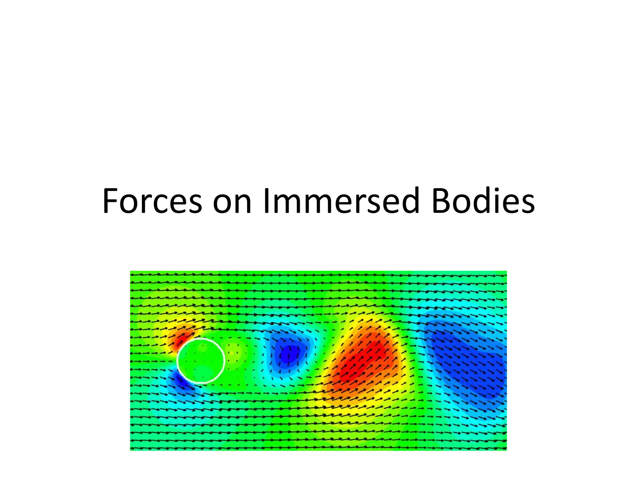
SlideShare a Scribd company logo
1 of 28
Forces on Immersed Bodies
• Up till now fluid flow within pipes have been
studies (internal flow).
• Next, flow of fluids over bodies that are
immersed in a fluid, called external flow will
be studied.
• emphasis on the resulting lift and drag forces
• When a body is immersed in a real fluid, which is
flowing at a uniform velocity U, the fluid will exert
a force on the body.
• The total force (FR) can be resolved in two
components:
– 1. Drag (FD): Component of the total force in the
direction of motion of fluid.
– 2. Lift (FL): Component of the total force in the
perpendicular direction of the motion of fluid. It
occurs only when the axis of the body is inclined to
the direction of fluid flow. If the axis of the body is
parallel to the fluid flow, lift force will be zero.
• Examples include drag force acting on
automobiles, power lines, trees, and
underwater pipelines;
• Lift developed by airplane wings; upward draft
of rain, snow, hail, and dust particles in high
winds; the transportation of red blood cells by
blood flow;
• the vibration and noise generated by bodies
moving in a fluid; and the power generated by
wind turbines.
• It is a common experience that a body meets
some resistance when it is forced to move
through a fluid, especially a liquid.
• It is very difficult to walk in water because of
the much greater resistance it offers to motion
compared to air.
• High winds knocking down trees, power lines,
and even trailers and felt the strong “push”
the wind exerts on your body
• Same feeling is observed when you extend your
arm out of the window of a moving car.
• A fluid may exert forces and moments on a body
in and about various directions.
• The force a flowing fluid exerts on a body in the
flow direction is called drag.
• The drag force can be measured directly by
simply attaching the body subjected to fluid flow
to a calibrated spring and measuring the
displacement in the flow direction
• Bodies subjected to fluid flow are classified as being
streamlined or blunt, depending on their overall shape.
• A body is said to be streamlined if a conscious effort is
made to align its shape with the anticipated
streamlines in the flow.
• Streamlined bodies such as race cars and airplanes
appear to be contoured and sleek. Otherwise, a body
(such as a building) tends to block the flow and is said
to be bluff or blunt.
• Usually it is much easier to force a streamlined body
through a fluid, and thus streamlining has been of
great importance in the design of vehicles and
airplanes
• Drag is usually an undesirable effect, like
friction, and we do our best to minimize it.
• Reduction of drag is closely associated with
the reduction of fuel consumption in
automobiles, submarines, and aircraft;
improved safety and durability of structures
subjected to high winds; and reduction of
noise
• A stationary fluid exerts only normal pressure forces on
the surface of a body immersed in it.
• A moving fluid, however, also exerts tangential shear
forces on the surface because of the no-slip condition
caused by viscous effects.
• Both of these forces, in general, have components in
the direction of flow, and thus the drag force is due to
the combined effects of pressure and wall shear forces
in the flow direction.
• The components of the pressure and wall shear forces
in the direction normal to the flow tend to move the
body in that direction, and their sum is called lift.
• The pressure and shear
forces acting on a
differential area dA on the
surface are PdA and τw
dA, respectively.
• Drag force and the lift
force acting on dA in two-
dimensional flow are
• where θ is the angle that the outer normal of
dA makes with the positive flow direction.
• The total drag and lift forces acting on the
body are determined by
• In the special case of a thin flat plate aligned
parallel to the flow direction, the drag force
depends on the wall shear only and is
independent of pressure since θ=90°.
• When the flat plate is placed normal to the flow
direction, however, the drag force depends on
the pressure only and is independent of wall
shear since the shear stress in this case acts in
the direction normal to flow and θ=0°. If the flat
plate is tilted at an angle relative to the flow
direction, then the drag force depends on both
the pressure and the shear stress
• The drag and lift forces depend on the density r
of the fluid, the upstream velocity V, and the size,
shape, and orientation of the body, among other
things, and it is not practical to list these forces
for a variety of situations.
• Instead, it is found convenient to work with
appropriate dimensionless numbers that
represent the drag and lift characteristics of the
body.
• These numbers are the drag coefficient CD, and
the lift coefficient CL, and they are defined as
• where A is ordinarily the frontal area (the area
projected on a plane normal to the direction of flow) of
the body. In other words, A is the area that would be
seen by a person looking at the body from the
direction of the approaching fluid.
• The frontal area of a cylinder of diameter D and length
L, for example, is A = LD. In lift calculations of some
thin bodies, such as airfoils, A is taken to be the
planform area, which is the area seen by a person
looking at the body from above in a direction normal to
the body.
Drag on a sphere (stokes law)
• For case of an ideal fluid flowing past a sphere, there is no
drag
• Consider the case of flow of a real fluid past a sphere
• Let D be the diameter, V be the velocity of flow of fluid with
density ρ and viscosity μ
• If the velocity of flow is very small or the fluid is very viscous
such that Reynold’s number is quite small (Re<=2)
• Viscous forces are much more predominant than inertial
forces
• George Gabriel Stokes analysed the flow around a sphere
under very low velocities and found that total drag force is
given by
• Two third of the drag force is contributed by skin friction and
one third by pressure difference
(skin friction drag)
DV
FD 
3

DV
DV
FD 
 2
3
3
2
3
2


(pressure drag)
The total drag is given by
Where A is the projected area=πD2/4
DV
DV
FD 
 
 3
3
1
3
1
A
V
C
F D
D
2
2


By equating the two equations for FD
Which is called Stokes Law.
2
2
4
2
3 D
V
C
DV D


 

e
D
R
VD
C
24
24




Terminal velocity of a body
• Maximum velocity attained by a falling body is known as the
terminal velocity
• If a body is allowed to fall from rest, its velocity increases due
to gravitational acceleration
• The increase in velocity also increases the drag force opposing
the motion of the body
• when drag force = weight of body, acceleration ceases, net
external force acting on the body becomes zero making the
body to move at constant speed called terminal velocity
W=FD+B
Or
FD=W-B
  g
d
g
d
W s
s 


 3
3
6
2
/
3
4


  g
d
g
d
B f
f 


 3
3
6
2
/
3
4


Drag force will be given by
 g
d
B
W
F f
s
D 





 3
6
Application of stokes law
• To calculate the terminal velocity of a falling
sphere and hence the viscosity of the fluid
• Desilting the river flow
• Sanitary engineering-treatment of raw water
and sewerage water
16. Forces on Immersed bodies in fluid .pptx

More Related Content

Similar to 16. Forces on Immersed bodies in fluid .pptx

Viscous-Laminar-Flows-Lesson-1-External-Flows-Handout (1) (1).pptx
Viscous-Laminar-Flows-Lesson-1-External-Flows-Handout (1) (1).pptxViscous-Laminar-Flows-Lesson-1-External-Flows-Handout (1) (1).pptx
Viscous-Laminar-Flows-Lesson-1-External-Flows-Handout (1) (1).pptx
Muhammad Dzaky Fawwaz
 
Fluid mechanics-ppt
Fluid mechanics-pptFluid mechanics-ppt
Fluid mechanics-ppt
Anil Rout
 
48_25795_ME362_2020_1__2_1_Lecture 1- Fluid 1 - Introduction to Fluid Mechani...
48_25795_ME362_2020_1__2_1_Lecture 1- Fluid 1 - Introduction to Fluid Mechani...48_25795_ME362_2020_1__2_1_Lecture 1- Fluid 1 - Introduction to Fluid Mechani...
48_25795_ME362_2020_1__2_1_Lecture 1- Fluid 1 - Introduction to Fluid Mechani...
sishu h/mariam
 

Similar to 16. Forces on Immersed bodies in fluid .pptx (20)

What are Submerged Bodies
What are Submerged BodiesWhat are Submerged Bodies
What are Submerged Bodies
 
Viscous-Laminar-Flows-Lesson-1-External-Flows-Handout (1) (1).pptx
Viscous-Laminar-Flows-Lesson-1-External-Flows-Handout (1) (1).pptxViscous-Laminar-Flows-Lesson-1-External-Flows-Handout (1) (1).pptx
Viscous-Laminar-Flows-Lesson-1-External-Flows-Handout (1) (1).pptx
 
Drag force & Lift
Drag force & LiftDrag force & Lift
Drag force & Lift
 
FMM Unit 1. Define the expression for Reynold's numberpptx
FMM Unit 1. Define the expression for Reynold's numberpptxFMM Unit 1. Define the expression for Reynold's numberpptx
FMM Unit 1. Define the expression for Reynold's numberpptx
 
Sandeep fm ppt
Sandeep fm pptSandeep fm ppt
Sandeep fm ppt
 
Notches
NotchesNotches
Notches
 
Liquid &amp; electrochemistry
Liquid &amp; electrochemistryLiquid &amp; electrochemistry
Liquid &amp; electrochemistry
 
Hydraulic Engineering Practical file
Hydraulic Engineering Practical file Hydraulic Engineering Practical file
Hydraulic Engineering Practical file
 
Lecture in open channel flow
Lecture in open channel flowLecture in open channel flow
Lecture in open channel flow
 
FLUID.ppt
FLUID.pptFLUID.ppt
FLUID.ppt
 
FLUID.ppt
FLUID.pptFLUID.ppt
FLUID.ppt
 
FLUID.ppt
FLUID.pptFLUID.ppt
FLUID.ppt
 
Chapter 6 FUNDAMENTALS OF CONVECTION
Chapter 6FUNDAMENTALS OF CONVECTIONChapter 6FUNDAMENTALS OF CONVECTION
Chapter 6 FUNDAMENTALS OF CONVECTION
 
FLUID - Copy.ppt
FLUID - Copy.pptFLUID - Copy.ppt
FLUID - Copy.ppt
 
Fluid Mechanics.pdf
Fluid Mechanics.pdfFluid Mechanics.pdf
Fluid Mechanics.pdf
 
Boundary layer PCS1.pptx Fluid Mechanics and Fluid Dynamics
Boundary layer PCS1.pptx Fluid Mechanics and Fluid DynamicsBoundary layer PCS1.pptx Fluid Mechanics and Fluid Dynamics
Boundary layer PCS1.pptx Fluid Mechanics and Fluid Dynamics
 
Lecture 1 introduction to aerodynamics.pptx
Lecture 1 introduction to aerodynamics.pptxLecture 1 introduction to aerodynamics.pptx
Lecture 1 introduction to aerodynamics.pptx
 
Fluid mechanics-ppt
Fluid mechanics-pptFluid mechanics-ppt
Fluid mechanics-ppt
 
48_25795_ME362_2020_1__2_1_Lecture 1- Fluid 1 - Introduction to Fluid Mechani...
48_25795_ME362_2020_1__2_1_Lecture 1- Fluid 1 - Introduction to Fluid Mechani...48_25795_ME362_2020_1__2_1_Lecture 1- Fluid 1 - Introduction to Fluid Mechani...
48_25795_ME362_2020_1__2_1_Lecture 1- Fluid 1 - Introduction to Fluid Mechani...
 
8fmm (1).ppt
8fmm (1).ppt8fmm (1).ppt
8fmm (1).ppt
 

Recently uploaded

1_Introduction + EAM Vocabulary + how to navigate in EAM.pdf
1_Introduction + EAM Vocabulary + how to navigate in EAM.pdf1_Introduction + EAM Vocabulary + how to navigate in EAM.pdf
1_Introduction + EAM Vocabulary + how to navigate in EAM.pdf
AldoGarca30
 
Call Girls in South Ex (delhi) call me [🔝9953056974🔝] escort service 24X7
Call Girls in South Ex (delhi) call me [🔝9953056974🔝] escort service 24X7Call Girls in South Ex (delhi) call me [🔝9953056974🔝] escort service 24X7
Call Girls in South Ex (delhi) call me [🔝9953056974🔝] escort service 24X7
9953056974 Low Rate Call Girls In Saket, Delhi NCR
 

Recently uploaded (20)

S1S2 B.Arch MGU - HOA1&2 Module 3 -Temple Architecture of Kerala.pptx
S1S2 B.Arch MGU - HOA1&2 Module 3 -Temple Architecture of Kerala.pptxS1S2 B.Arch MGU - HOA1&2 Module 3 -Temple Architecture of Kerala.pptx
S1S2 B.Arch MGU - HOA1&2 Module 3 -Temple Architecture of Kerala.pptx
 
UNIT 4 PTRP final Convergence in probability.pptx
UNIT 4 PTRP final Convergence in probability.pptxUNIT 4 PTRP final Convergence in probability.pptx
UNIT 4 PTRP final Convergence in probability.pptx
 
COST-EFFETIVE and Energy Efficient BUILDINGS ptx
COST-EFFETIVE  and Energy Efficient BUILDINGS ptxCOST-EFFETIVE  and Energy Efficient BUILDINGS ptx
COST-EFFETIVE and Energy Efficient BUILDINGS ptx
 
PE 459 LECTURE 2- natural gas basic concepts and properties
PE 459 LECTURE 2- natural gas basic concepts and propertiesPE 459 LECTURE 2- natural gas basic concepts and properties
PE 459 LECTURE 2- natural gas basic concepts and properties
 
Thermal Engineering -unit - III & IV.ppt
Thermal Engineering -unit - III & IV.pptThermal Engineering -unit - III & IV.ppt
Thermal Engineering -unit - III & IV.ppt
 
Unit 4_Part 1 CSE2001 Exception Handling and Function Template and Class Temp...
Unit 4_Part 1 CSE2001 Exception Handling and Function Template and Class Temp...Unit 4_Part 1 CSE2001 Exception Handling and Function Template and Class Temp...
Unit 4_Part 1 CSE2001 Exception Handling and Function Template and Class Temp...
 
Ground Improvement Technique: Earth Reinforcement
Ground Improvement Technique: Earth ReinforcementGround Improvement Technique: Earth Reinforcement
Ground Improvement Technique: Earth Reinforcement
 
fitting shop and tools used in fitting shop .ppt
fitting shop and tools used in fitting shop .pptfitting shop and tools used in fitting shop .ppt
fitting shop and tools used in fitting shop .ppt
 
Computer Networks Basics of Network Devices
Computer Networks  Basics of Network DevicesComputer Networks  Basics of Network Devices
Computer Networks Basics of Network Devices
 
School management system project Report.pdf
School management system project Report.pdfSchool management system project Report.pdf
School management system project Report.pdf
 
AIRCANVAS[1].pdf mini project for btech students
AIRCANVAS[1].pdf mini project for btech studentsAIRCANVAS[1].pdf mini project for btech students
AIRCANVAS[1].pdf mini project for btech students
 
Orlando’s Arnold Palmer Hospital Layout Strategy-1.pptx
Orlando’s Arnold Palmer Hospital Layout Strategy-1.pptxOrlando’s Arnold Palmer Hospital Layout Strategy-1.pptx
Orlando’s Arnold Palmer Hospital Layout Strategy-1.pptx
 
Online food ordering system project report.pdf
Online food ordering system project report.pdfOnline food ordering system project report.pdf
Online food ordering system project report.pdf
 
457503602-5-Gas-Well-Testing-and-Analysis-pptx.pptx
457503602-5-Gas-Well-Testing-and-Analysis-pptx.pptx457503602-5-Gas-Well-Testing-and-Analysis-pptx.pptx
457503602-5-Gas-Well-Testing-and-Analysis-pptx.pptx
 
1_Introduction + EAM Vocabulary + how to navigate in EAM.pdf
1_Introduction + EAM Vocabulary + how to navigate in EAM.pdf1_Introduction + EAM Vocabulary + how to navigate in EAM.pdf
1_Introduction + EAM Vocabulary + how to navigate in EAM.pdf
 
Thermal Engineering-R & A / C - unit - V
Thermal Engineering-R & A / C - unit - VThermal Engineering-R & A / C - unit - V
Thermal Engineering-R & A / C - unit - V
 
NO1 Top No1 Amil Baba In Azad Kashmir, Kashmir Black Magic Specialist Expert ...
NO1 Top No1 Amil Baba In Azad Kashmir, Kashmir Black Magic Specialist Expert ...NO1 Top No1 Amil Baba In Azad Kashmir, Kashmir Black Magic Specialist Expert ...
NO1 Top No1 Amil Baba In Azad Kashmir, Kashmir Black Magic Specialist Expert ...
 
DC MACHINE-Motoring and generation, Armature circuit equation
DC MACHINE-Motoring and generation, Armature circuit equationDC MACHINE-Motoring and generation, Armature circuit equation
DC MACHINE-Motoring and generation, Armature circuit equation
 
Call Girls in South Ex (delhi) call me [🔝9953056974🔝] escort service 24X7
Call Girls in South Ex (delhi) call me [🔝9953056974🔝] escort service 24X7Call Girls in South Ex (delhi) call me [🔝9953056974🔝] escort service 24X7
Call Girls in South Ex (delhi) call me [🔝9953056974🔝] escort service 24X7
 
Introduction to Serverless with AWS Lambda
Introduction to Serverless with AWS LambdaIntroduction to Serverless with AWS Lambda
Introduction to Serverless with AWS Lambda
 

16. Forces on Immersed bodies in fluid .pptx

  • 2. • Up till now fluid flow within pipes have been studies (internal flow). • Next, flow of fluids over bodies that are immersed in a fluid, called external flow will be studied. • emphasis on the resulting lift and drag forces
  • 3. • When a body is immersed in a real fluid, which is flowing at a uniform velocity U, the fluid will exert a force on the body. • The total force (FR) can be resolved in two components: – 1. Drag (FD): Component of the total force in the direction of motion of fluid. – 2. Lift (FL): Component of the total force in the perpendicular direction of the motion of fluid. It occurs only when the axis of the body is inclined to the direction of fluid flow. If the axis of the body is parallel to the fluid flow, lift force will be zero.
  • 4.
  • 5. • Examples include drag force acting on automobiles, power lines, trees, and underwater pipelines; • Lift developed by airplane wings; upward draft of rain, snow, hail, and dust particles in high winds; the transportation of red blood cells by blood flow; • the vibration and noise generated by bodies moving in a fluid; and the power generated by wind turbines.
  • 6. • It is a common experience that a body meets some resistance when it is forced to move through a fluid, especially a liquid. • It is very difficult to walk in water because of the much greater resistance it offers to motion compared to air. • High winds knocking down trees, power lines, and even trailers and felt the strong “push” the wind exerts on your body
  • 7.
  • 8. • Same feeling is observed when you extend your arm out of the window of a moving car. • A fluid may exert forces and moments on a body in and about various directions. • The force a flowing fluid exerts on a body in the flow direction is called drag. • The drag force can be measured directly by simply attaching the body subjected to fluid flow to a calibrated spring and measuring the displacement in the flow direction
  • 9. • Bodies subjected to fluid flow are classified as being streamlined or blunt, depending on their overall shape. • A body is said to be streamlined if a conscious effort is made to align its shape with the anticipated streamlines in the flow. • Streamlined bodies such as race cars and airplanes appear to be contoured and sleek. Otherwise, a body (such as a building) tends to block the flow and is said to be bluff or blunt. • Usually it is much easier to force a streamlined body through a fluid, and thus streamlining has been of great importance in the design of vehicles and airplanes
  • 10.
  • 11. • Drag is usually an undesirable effect, like friction, and we do our best to minimize it. • Reduction of drag is closely associated with the reduction of fuel consumption in automobiles, submarines, and aircraft; improved safety and durability of structures subjected to high winds; and reduction of noise
  • 12. • A stationary fluid exerts only normal pressure forces on the surface of a body immersed in it. • A moving fluid, however, also exerts tangential shear forces on the surface because of the no-slip condition caused by viscous effects. • Both of these forces, in general, have components in the direction of flow, and thus the drag force is due to the combined effects of pressure and wall shear forces in the flow direction. • The components of the pressure and wall shear forces in the direction normal to the flow tend to move the body in that direction, and their sum is called lift.
  • 13. • The pressure and shear forces acting on a differential area dA on the surface are PdA and τw dA, respectively. • Drag force and the lift force acting on dA in two- dimensional flow are
  • 14. • where θ is the angle that the outer normal of dA makes with the positive flow direction. • The total drag and lift forces acting on the body are determined by
  • 15. • In the special case of a thin flat plate aligned parallel to the flow direction, the drag force depends on the wall shear only and is independent of pressure since θ=90°.
  • 16. • When the flat plate is placed normal to the flow direction, however, the drag force depends on the pressure only and is independent of wall shear since the shear stress in this case acts in the direction normal to flow and θ=0°. If the flat plate is tilted at an angle relative to the flow direction, then the drag force depends on both the pressure and the shear stress
  • 17. • The drag and lift forces depend on the density r of the fluid, the upstream velocity V, and the size, shape, and orientation of the body, among other things, and it is not practical to list these forces for a variety of situations. • Instead, it is found convenient to work with appropriate dimensionless numbers that represent the drag and lift characteristics of the body. • These numbers are the drag coefficient CD, and the lift coefficient CL, and they are defined as
  • 18. • where A is ordinarily the frontal area (the area projected on a plane normal to the direction of flow) of the body. In other words, A is the area that would be seen by a person looking at the body from the direction of the approaching fluid. • The frontal area of a cylinder of diameter D and length L, for example, is A = LD. In lift calculations of some thin bodies, such as airfoils, A is taken to be the planform area, which is the area seen by a person looking at the body from above in a direction normal to the body.
  • 19. Drag on a sphere (stokes law) • For case of an ideal fluid flowing past a sphere, there is no drag • Consider the case of flow of a real fluid past a sphere • Let D be the diameter, V be the velocity of flow of fluid with density ρ and viscosity μ • If the velocity of flow is very small or the fluid is very viscous such that Reynold’s number is quite small (Re<=2) • Viscous forces are much more predominant than inertial forces
  • 20. • George Gabriel Stokes analysed the flow around a sphere under very low velocities and found that total drag force is given by • Two third of the drag force is contributed by skin friction and one third by pressure difference (skin friction drag) DV FD  3  DV DV FD   2 3 3 2 3 2  
  • 21. (pressure drag) The total drag is given by Where A is the projected area=πD2/4 DV DV FD     3 3 1 3 1 A V C F D D 2 2  
  • 22. By equating the two equations for FD Which is called Stokes Law. 2 2 4 2 3 D V C DV D      e D R VD C 24 24    
  • 23. Terminal velocity of a body • Maximum velocity attained by a falling body is known as the terminal velocity • If a body is allowed to fall from rest, its velocity increases due to gravitational acceleration • The increase in velocity also increases the drag force opposing the motion of the body • when drag force = weight of body, acceleration ceases, net external force acting on the body becomes zero making the body to move at constant speed called terminal velocity
  • 24. W=FD+B Or FD=W-B   g d g d W s s     3 3 6 2 / 3 4     g d g d B f f     3 3 6 2 / 3 4  
  • 25. Drag force will be given by  g d B W F f s D        3 6
  • 26.
  • 27. Application of stokes law • To calculate the terminal velocity of a falling sphere and hence the viscosity of the fluid • Desilting the river flow • Sanitary engineering-treatment of raw water and sewerage water