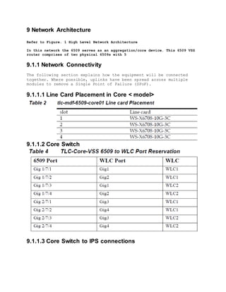
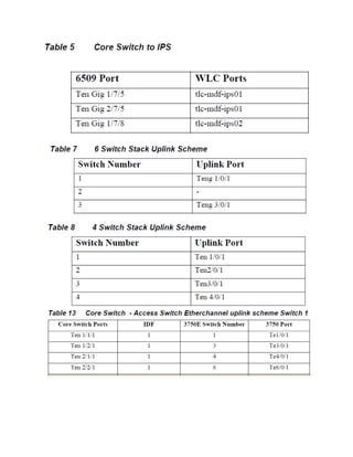
<NAME OF COMPANY/SCHOOL>
Low Level Design
Version 1.1
1 Contents
1 Contents..........................................................2
2 Figures...........................................................6
3 Tables ..........................................................7
4 Document Information.............. ................... ...........9
4.1 Review and Distribution.................................. 9
4.2 Modification History............................. ........9
5 Document Acceptance Certificate...................
6 About This Design Document .............
6.1 Document Purpose.........................
6.2 Intended Audience..........................
6.3 Scope ...............................................
6.4 Document Usage Guidelines...................
6.5 Assumptions and Caveats....................
6.6 Related Documents........................
6.7 References .....................................
7 Network Overview........................................
7.1 Network Layout:..........................................
7.2 Design Considerations................................
8 Physical Network Design..................................
8.1 Network Hardware Components...........................
8.1.1 Business Network BoQ..................
8.2 LAN Wiring Diagram and Physical Lay-out
8.2.1 First Floor Wiring Lay-out
8.3 Cut Sheets
8.3.1 MDF to Room #
9 Network Architecture
9.1.1 Network Connectivity
9.1.1.1 Line Card Placement in Core 6509 of Business
Network
9.1.1.2 Core Switch to WLC
9.1.1.3 Core Switch to IPS Connections
9.2 Labelling Convention
9.3 Interface Description
9.3.1 Switch Virtual Interface (SVI) Descriptions
9.3.2 PortChannel Interface Descriptions
9.4 Software Requirements
9.4.1 Software Justifications
10 Logical Network Design
10.1 Network Design
10.2 VLAN
10.4 IP Addressing
10.4.1 Learning Center Address Allocation
10.4.2 IP Scheme
10.5 Infrastructure Routing
10.5.1 Quality of Service
10.5.2 IP Multicast
10.6 Infrastructure Security
10.6.1 Control Plane Policing
10.6.2 Storm Control
10.6.3 DHCP Snooping
10.6.3.1 DHCP Scope Exhaustion
10.6.3.2 Rogue DHCP Server
10.6.3.3 DHCP Snooping Configuration guidelines
2 Figures
Figure 1 Network Lay-out 23
3 Tables
Table 1 Business Network 21
4 Document Information
Author:
4.1 Review and Distribution
Organisation Name Title Organisation Name Title Organisation Name Title
4.2 Modification History
Rev Date Originator Status Comment
5 Document Acceptance Certificate
Title:
Version:
Name _________________________ Name: ________________________
Title ________________________ Title ________________________
Company_______________________ Company_______________________
Signature ____________________ Signature ____________________
Date _________________________ Date _________________________
6 About This Design Document
Author:
Reference Number:
6.1 Document Purpose
This document cover the Low Level Design of the Infrastructure related to
<name of network>. It discusses the physical and logical connectivity as well
as IP addressing. Furthermore, it outlines the layer 2 and layer 3 protocols
and features required to run the services in a redundant and available
manner.
6.2 Intended Audience
 <Your Stakeholders>
6.3 Scope
The scope of this document is only related to the <network>. The
configuration of devices outside this network is not in scope.
6.4 Scope
A Low Level Design Document (LLD) consists of a number of components. These
include
• Customer Requirements
• Generic Content
• Best Practice Guidance
• Customer Specific Content
There is an overall thread that brings these elements together as an
integrated document.
6.5 Assumptions and Caveats
There are several assumptions and caveats associated with any network
deployment. These are summarized below:
6.6 Related Documents
1. High Level Design
6.7 References
[REF-1] Cisco Product Documentation
http://www.cisco.com/univercd/cc/td/doc/product/index.htm
7 Network Overview
< Give a brief history of the company/school>
7.1 Network Layout:
Figure 1 Network Lay-out
7.2 Design Considerations
The following design principles have been considered in the preparation of
this design of Learning Center Network.
1. Scalability
2. Reliability
3. Availability
4. Manageability
5. Security
6. Performance
7. Network Stability
8 Physical Network Design
8.1 Network Hardware Components
The following network lists the Bill of Quantities for the Business as
well as the Utility Networks.
8.1.1 Business Network
This section provides details about hardware that will be deployed in
<name> network.
Item Product No. Description Quantity
MDF
IDF – 1
Table 1 Business Network BoQ
8.2 LAN Wiring and Physical Lay-out
Figure 2 Sample Physical Topology
8.3 Cut sheets
Figure #: Complete Logical Topology
Table #: Cut sheet for IDF -1
9 Network Architecture
Refer to Figure. 1 High Level Network Architecture
In this network the 6509 serves as an aggregation/core device. This 6509 VSS
router comprises of two physical 6509s with 5
9.1.1 Network Connectivity
The following section explains how the equipment will be connected
together. Where possible, uplinks have been spread across multiple
modules to remove a Single Point of Failure (SPoF).
9.1.1.1 Line Card Placement in Core < model>
9.1.1.2 Core Switch
9.1.1.3 Core Switch to IPS connections
9.2 Labelling Convention
The labeling convention will follow the host naming convention, with
the addition of the stack member number for devices in a Stack. It is
important to be able to refer to a switch in the stack as an
individual entity.
The switches in a stack will be labeled as follows:
10 Logical Network Design
10.1 Network Design
< Make an explanation of the whole topology>
10.2 VLAN
The table below shows the VLAN scheme.
10.4 IP Addressing
10.4.1 Address Allocation
The IP address space below will be implemented
10.5 Infrastructure Routing
<discuss the different routing protocols used>
10.6 Infrastructure Security
10.6.1 Control Plane Policing
10.6.2 DHCP Snooping
10.6.3 Dynamic ARP inspection
10.6.4 Port Security
10.7 Network Services
< talk about the different services such as DNS, DHCP relay>
10.8 Access Nework Design
10.9 Infrastructure Management

153285580 lld-template

  • 1.
    <NAME OF COMPANY/SCHOOL> LowLevel Design Version 1.1
  • 2.
    1 Contents 1 Contents..........................................................2 2Figures...........................................................6 3 Tables ..........................................................7 4 Document Information.............. ................... ...........9 4.1 Review and Distribution.................................. 9 4.2 Modification History............................. ........9 5 Document Acceptance Certificate................... 6 About This Design Document ............. 6.1 Document Purpose......................... 6.2 Intended Audience.......................... 6.3 Scope ............................................... 6.4 Document Usage Guidelines................... 6.5 Assumptions and Caveats.................... 6.6 Related Documents........................ 6.7 References ..................................... 7 Network Overview........................................ 7.1 Network Layout:.......................................... 7.2 Design Considerations................................ 8 Physical Network Design.................................. 8.1 Network Hardware Components........................... 8.1.1 Business Network BoQ.................. 8.2 LAN Wiring Diagram and Physical Lay-out 8.2.1 First Floor Wiring Lay-out 8.3 Cut Sheets 8.3.1 MDF to Room # 9 Network Architecture 9.1.1 Network Connectivity 9.1.1.1 Line Card Placement in Core 6509 of Business Network 9.1.1.2 Core Switch to WLC 9.1.1.3 Core Switch to IPS Connections 9.2 Labelling Convention 9.3 Interface Description 9.3.1 Switch Virtual Interface (SVI) Descriptions 9.3.2 PortChannel Interface Descriptions 9.4 Software Requirements 9.4.1 Software Justifications 10 Logical Network Design 10.1 Network Design 10.2 VLAN 10.4 IP Addressing 10.4.1 Learning Center Address Allocation 10.4.2 IP Scheme 10.5 Infrastructure Routing 10.5.1 Quality of Service 10.5.2 IP Multicast 10.6 Infrastructure Security 10.6.1 Control Plane Policing 10.6.2 Storm Control
  • 3.
    10.6.3 DHCP Snooping 10.6.3.1DHCP Scope Exhaustion 10.6.3.2 Rogue DHCP Server 10.6.3.3 DHCP Snooping Configuration guidelines
  • 4.
    2 Figures Figure 1Network Lay-out 23
  • 5.
    3 Tables Table 1Business Network 21
  • 6.
    4 Document Information Author: 4.1Review and Distribution Organisation Name Title Organisation Name Title Organisation Name Title 4.2 Modification History Rev Date Originator Status Comment
  • 7.
    5 Document AcceptanceCertificate Title: Version: Name _________________________ Name: ________________________ Title ________________________ Title ________________________ Company_______________________ Company_______________________ Signature ____________________ Signature ____________________ Date _________________________ Date _________________________ Name _________________________ Name: ________________________ Title ________________________ Title ________________________ Company_______________________ Company_______________________ Signature ____________________ Signature ____________________ Date _________________________ Date _________________________ Name _________________________ Name: ________________________ Title ________________________ Title ________________________ Company_______________________ Company_______________________ Signature ____________________ Signature ____________________ Date _________________________ Date _________________________
  • 8.
    6 About ThisDesign Document Author: Reference Number: 6.1 Document Purpose This document cover the Low Level Design of the Infrastructure related to <name of network>. It discusses the physical and logical connectivity as well as IP addressing. Furthermore, it outlines the layer 2 and layer 3 protocols and features required to run the services in a redundant and available manner. 6.2 Intended Audience  <Your Stakeholders> 6.3 Scope The scope of this document is only related to the <network>. The configuration of devices outside this network is not in scope. 6.4 Scope A Low Level Design Document (LLD) consists of a number of components. These include • Customer Requirements • Generic Content • Best Practice Guidance • Customer Specific Content There is an overall thread that brings these elements together as an integrated document. 6.5 Assumptions and Caveats There are several assumptions and caveats associated with any network deployment. These are summarized below: 6.6 Related Documents 1. High Level Design 6.7 References [REF-1] Cisco Product Documentation http://www.cisco.com/univercd/cc/td/doc/product/index.htm
  • 9.
    7 Network Overview <Give a brief history of the company/school> 7.1 Network Layout: Figure 1 Network Lay-out
  • 10.
    7.2 Design Considerations Thefollowing design principles have been considered in the preparation of this design of Learning Center Network. 1. Scalability 2. Reliability 3. Availability 4. Manageability 5. Security 6. Performance 7. Network Stability
  • 11.
    8 Physical NetworkDesign 8.1 Network Hardware Components The following network lists the Bill of Quantities for the Business as well as the Utility Networks. 8.1.1 Business Network This section provides details about hardware that will be deployed in <name> network. Item Product No. Description Quantity MDF IDF – 1 Table 1 Business Network BoQ 8.2 LAN Wiring and Physical Lay-out Figure 2 Sample Physical Topology
  • 12.
    8.3 Cut sheets Figure#: Complete Logical Topology
  • 13.
    Table #: Cutsheet for IDF -1
  • 14.
    9 Network Architecture Referto Figure. 1 High Level Network Architecture In this network the 6509 serves as an aggregation/core device. This 6509 VSS router comprises of two physical 6509s with 5 9.1.1 Network Connectivity The following section explains how the equipment will be connected together. Where possible, uplinks have been spread across multiple modules to remove a Single Point of Failure (SPoF). 9.1.1.1 Line Card Placement in Core < model> 9.1.1.2 Core Switch 9.1.1.3 Core Switch to IPS connections
  • 16.
    9.2 Labelling Convention Thelabeling convention will follow the host naming convention, with the addition of the stack member number for devices in a Stack. It is important to be able to refer to a switch in the stack as an individual entity. The switches in a stack will be labeled as follows:
  • 17.
    10 Logical NetworkDesign 10.1 Network Design < Make an explanation of the whole topology> 10.2 VLAN The table below shows the VLAN scheme.
  • 18.
    10.4 IP Addressing 10.4.1Address Allocation The IP address space below will be implemented 10.5 Infrastructure Routing <discuss the different routing protocols used>
  • 19.
    10.6 Infrastructure Security 10.6.1Control Plane Policing 10.6.2 DHCP Snooping
  • 20.
    10.6.3 Dynamic ARPinspection 10.6.4 Port Security 10.7 Network Services < talk about the different services such as DNS, DHCP relay> 10.8 Access Nework Design 10.9 Infrastructure Management