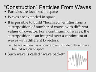
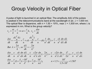
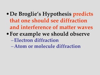
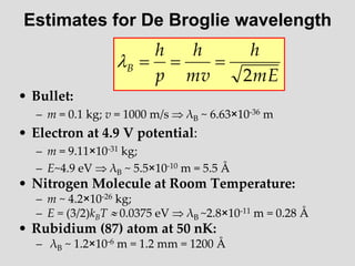
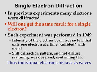
- Louis de Broglie hypothesized that all matter exhibits both wave and particle properties, with a wavelength inversely proportional to momentum, just as light does.
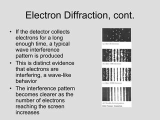
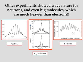
- Experiments observing diffraction and interference of electrons, neutrons, atoms and molecules provided evidence that matter has wave-like properties consistent with a de Broglie wavelength, demonstrating the wave-particle duality of all matter.
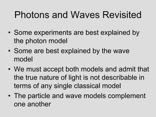
- The principle of complementarity states that matter and light cannot be fully described as either purely waves or particles, as the two models complement each other and neither is complete. Observing one property precludes observation of the other.


![Addition of Two Waves
)
2
sin(
)
2
cos(
2
)
sin(
)
sin(
)
,
(
t
kx
A
t
kx
A
t
kx
A
t
x
y
t
kx
A
t
kx
A
t
kx
A
t
x
y
cos
sin
2
)
sin(
)
sin(
)
,
(
Two sine waves traveling in the same direction:
Constructive and Destructive Interference
Two sine waves traveling in opposite directions create a standing wave
Two sine waves with different frequencies: Beats
]
2
(
2
(
sin[
]
)
2
/
(
)
2
/
cos[(
2
]
2
(
2
(
sin[
]
2
(
2
(
cos[
2
)
sin(
)
sin(
)
,
(
)
2
1
)
2
1
)
2
1
)
2
1
)
2
1
)
2
1
2
2
1
1
t
x
k
k
t
x
k
A
t
x
k
k
t
x
k
k
A
t
x
k
A
t
x
k
A
t
x
y
](https://image.slidesharecdn.com/12377224-230419105258-c3e48f68/85/12377224-ppt-37-320.jpg)
![Beat Notes and Group Velocity, vg
This represents a beat note with the amplitude of the beat moving at speed
dk
d
v
v
k
v
g
g
:
waves
of
on
distributi
continuous
of
ion
superposit
For
/
)
2
/
/(
)
2
/
(
]
2
(
2
(
sin[
]
)
2
/
(
)
2
/
cos[(
2
)
,
(
)
2
1
)
2
1
t
x
k
k
t
x
k
A
t
x
y
](https://image.slidesharecdn.com/12377224-230419105258-c3e48f68/85/12377224-ppt-38-320.jpg)
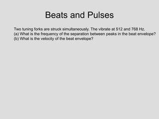
![Beats and Pulses
Two tuning forks are struck simultaneously. The vibrate at 512 and 768 Hz.
(a) What is the separation between peaks in the beat envelope?
(b) What is the velocity of the beat envelope?
(a)
The rapidly oscillating wave is multiplied by a more slowly varying envelope
with wave vector
]
2
(
2
(
sin[
]
)
2
/
(
)
2
/
cos[(
2
)
,
(
)
2
1
)
2
1
t
x
k
k
t
x
k
A
t
x
y
phase
beat
beat
beat
beat
beat
phase
phase
phase
phase
phase
phase
v
v
so
th
ofwaveleng
t
independen
is
sound
of
speed
ce
result
Expected
k
v
b
m
k
notes
beat
between
ce
Dis
m
k
k
k
m
v
f
v
k
m
v
f
v
k
mph
s
m
sound
of
speed
the
is
v
f
f
k
v
k
k
k
sin
344
)
35
.
9
03
.
14
/(
)
512
768
(
2
)
2
/
/(
)
2
/
(
)
(
70
.
2
33
.
2
/
2
/
2
:
tan
33
.
2
2
/
)
35
.
9
0
.
14
(
2
/
)
(
35
.
9
344
/
512
2
/
2
/
03
.
14
344
/
768
2
/
2
/
)
770
(
/
344
,
,
)
/
2
/(
2
/
2
/
)
(
2
/
1
1
2
1
1
1
1
1
2
2
2
1
2
](https://image.slidesharecdn.com/12377224-230419105258-c3e48f68/85/12377224-ppt-40-320.jpg)