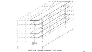
Equivalent Frame Method(EFM) ACI 13.7
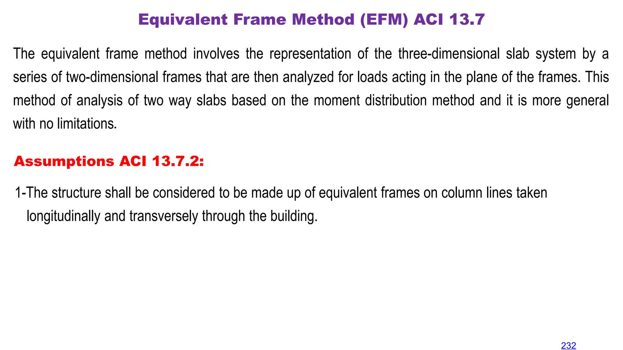
The equivalent frame method involves the representation of the three-dimensional slab system by a
series of two-dimensional frames that are then analyzed for loads acting in the plane of the frames. This
method of analysis of two way slabs based on the moment distribution method and it is more general
with no limitations.
Assumptions ACI 13.7.2:
1-The structure shall be considered to be made up of equivalent frames on column lines taken
longitudinally and transversely through the building.
232
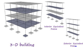
2- Each frameshall consist of a row of columns or supports and slab-beam strips, bounded laterally by
the centerline of panel on each side of the centerline of columns or supports.
Definitions of equivalent frame
234
4.
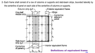
3- Columns orsupports shall be assumed to be attached to slab-beam strips by torsional members
transverse to the direction of the span for which moments are being determined (l1).
Definitions of equivalent frame
235
5.
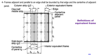
4- Frames adjacentand parallel to an edge shall be bounded by that edge and the centerline of adjacent
panel.
Definitions of
equivalent frame
236
6.
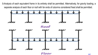
5-Analysis of eachequivalent frame in its entirety shall be permitted. Alternatively, for gravity loading, a
separate analysis of each floor or roof with far ends of columns considered fixed shall be permitted.
237
7.
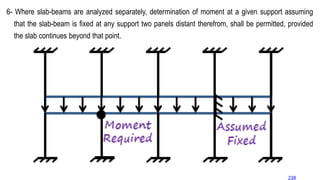
6- Where slab-beamsare analyzed separately, determination of moment at a given support assuming
that the slab-beam is fixed at any support two panels distant therefrom, shall be permitted, provided
the slab continues beyond that point.
238
8.
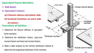
Equivalent Frame Members:
1-Slab Beam
2- Equivalent Column
a) Columns above and below slab.
b) Torsional members on each side
of column.
Procedure of Solution:
1- Determine the flexural stiffness of equivalent
frame members.
2- Determine the distribution factors, carry-over
moment factors and fixed end moment factors.
3- Make a table analysis by the moment distribution method to
determine the longitudinal distribution of the moments.
239
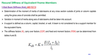
Flexural Stiffness ofEquivalent Frame Members
1-Slab Beam Stiffness (Ksb): ACI 13.7.3
Determination of the moment of inertia of slab-beams at any cross section outside of joints or column capitals
using the gross area of concrete shall be permitted.
Variation in moment of inertia along axis of slab-beams shall be taken into account.
A support is defined as a column, capital, bracket, or wall. A beam is not considered to be a support member for
the equivalent frame.
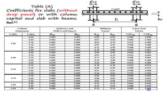
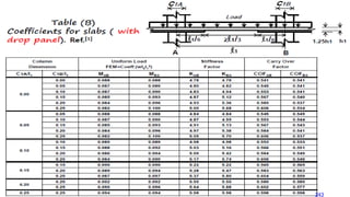
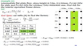
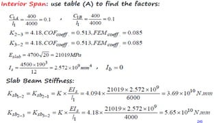
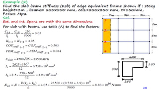
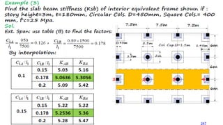
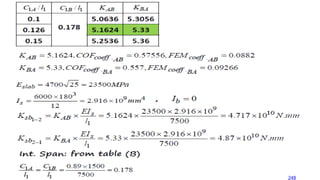
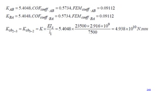
The stiffness factors (K), carry over factors (COF) and fixed end moment factors (FEM) can be determined from
tables A and B.
241