This document provides assembly and operating instructions for the KR AGILUS EX industrial robot. It includes:
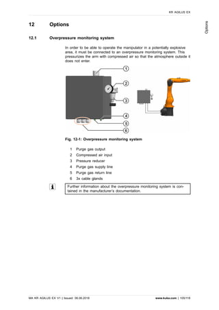
1. An overview of the robot system and description of the manipulator.
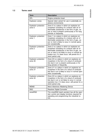
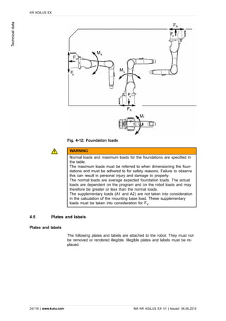
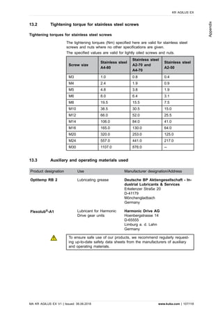
2. Technical data such as basic data, axis data, payloads, foundation loads, and plates/labels.
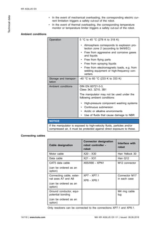
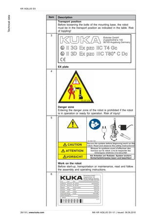
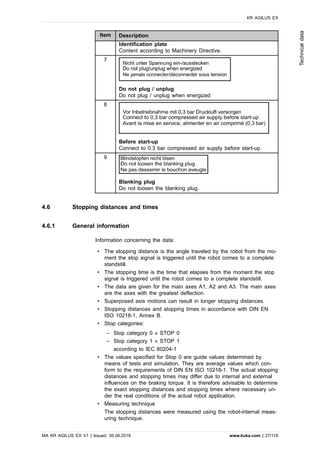
3. Safety information including safety functions, additional protective equipment, operating modes, safety measures, and applied norms/regulations.
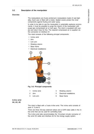
4. Planning details for robot placement, the mounting base, and integration into a machine.