
Recommended
More Related Content
What's hot
What's hot (20)
Similar to Ppt on water jet machining
Similar to Ppt on water jet machining (20)
Recently uploaded
Recently uploaded (20)
Ppt on water jet machining
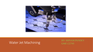
- 1. Water Jet Machining BY- SHIVAM PANDEY GME122705
- 2. INTRODUCTION Key element in WJM is a jet of water. Water jet travels at velocities as high as 900 m/s (approximately Mach 3). When the water stream strikes a work piece surface, the erosive force of water removes the material rapidly. The water, in this case, acts like a saw and cuts a narrow groove in the work piece material. True cold cutting process – no HAZ (Heat Affected Zones), mechanical stresses or operator and environmental hazards
- 3. PRINCIPLE The water jet machining involves directing a high pressure (150-1000 MPa) high velocity (540-1400 m/s) water jet (faster than the speed of sound) to the surface to be machined. The fluid flow rate is typically from 0.5 to 2.5 l/min The kinetic energy of water jet after striking the work surface is reduced to zero. The bulk of kinetic energy of jet is converted into pressure energy. If the local pressure caused by the water jet exceeds the strength of the surface being machined, the material from the surface gets eroded and a cavity is thus formed. Water is the most common fluid used, but additives such as alcohols, oil products and glycerol are added when they can be dissolved in water to improve the fluid characteristics.
- 4. Equipment Typical work materials involve soft metals, paper, cloth, wood, leather, rubber, plastics, and frozen food. If the work material is brittle it will fracture, if it is ductile, it will cut well . Water jet Machining consists of: ◦ Hydraulic Pump ◦ Intensifier ◦ Accumulator ◦ High Pressure Tubing ◦ Jet Cutting Nozzle ◦ Catcher
- 5. SCHEMATIC LAYOUT OF WJM
- 6. HYDRAULIC PUMP Powered from a 30 kilowatt (kW) electric motor Supplies oil at pressures as high as 117 bars. Compressed oil drives a reciprocating plunger pump termed an intensifier.
- 7. ITENSIFIER Accepts the water at low pressure(typically 4 bar) and expels it, through an accumulator, at higher pressures of 3800 bar. A limit switch, located at each end of the piston travel, signals the electronic controls to shift the directional control valve and reverses the piston direction. The intensifier assembly, with a plunger on each side of the piston, generates pressure in both directions.
- 8. ACCUMULATOR Maintains the continuous flow of the high-pressure water and eliminates pressure fluctuations. It relies on the compressibility of water (12 percent at 3800 bar) in order to maintain a uniform discharge pressure and water jet velocity, when the intensifier piston changes its direction.
- 9. HIGH PRESSURE TUBING Transports pressurized water to the cutting head. Typical tube diameters are 6 to 14 mm. The equipment allows for flexible movement of the cutting head. The cutting action is controlled either manually or through a remote-control valve specially designed for this purpose.
- 10. JET CUTTING NOZZLE Nozzle provides a water jet stream for optimum cutting of low-density, soft material that is considered unmachinable by conventional methods. Nozzles are normally made from synthetic sapphire. About 200 h of operation are expected from a nozzle, which becomes damaged by particles of dirt and the accumulation of mineral deposits on the orifice due to erosive water hardness. A longer nozzle life can be obtained through multistage filtration, which removes undesired solids of size greater than 0.45 μm.
- 11. CATCHER Acts as a reservoir for collecting the machining debris entrained in the water jet. Moreover, it reduces the noise levels [105 decibels (dB)] associated with the reduction in the velocity of the water jet from Mach 3 to subsonic levels.
- 12. parameters affecting the performance of WJM
- 13. PROCESS PARAMETERS JET NOZZLE Standoff distance - Gap between the jet nozzle (0.1–0.3 mm diameter) and the workpiece (2.5 – 6 mm). But larger the standoff distance, smaller would be the depth of cut. When cutting fiber-reinforced plastics, reports showed that the increase in machining rate and use of the small nozzle diameter increased the width of the damaged layer.
- 14. CUTTING WJM is limited to fibreglass and corrugated wood. Figure shows typical example of water jet cutting of water jet cutting of marble and application in the food industry. DRILLING The process drills precision-angled and -shaped holes in a variety of materials for which other processes such as EDM or EBM are too expensive or too slow.
- 15. DEBURRING The method uses large pressures to remove large burrs (3 mm height) in 12 mm diameter drilled holes in a hollow molybdenum-chromium steel shaft at 15 s using 700 bar pressure and a flow rate of 27 L/min. In this method burrs are broken off by the impact of water. A higher pressure (4000 bar) and a lower flow rate (2.5 L/min) are used to remove burrs from nonmetallic materials.
- 16. ADVANTAGES It has multidirectional cutting capacity. No heat is produced. Cuts can be started at any location without the need for predrilled holes. Wetting of the workpiece material is minimal. There is no deflection to the rest of the workpiece. The burr produced is minimal. The tool does not wear and, therefore, does not need sharpening. The process is environmentally safe. Hazardous airborne dust contamination and waste disposal problems that are common when using other cleaning methods are eliminated. There is multiple head processing. Simple fixturing eliminates costly and complicated tooling, which reduces turnaround time and lowers the cost. Grinding and polishing are eliminated, reducing secondary operation costs.
- 17. LIMITATIONS Very thick parts can not be cut with water jet cutting and still hold dimensional accuracy. If the part is too thick, the jet may dissipate some, and cause it to cut on a diagonal, or to have a wider cut at the bottom of the part than the top. It can also cause a rough wave pattern on the cut surface. It is not suitable for mass production because of high maintenance requirements. WATER JET LAG