DC MACHINE-Motoring and generation, Armature circuit equation
Dcs 6 rajeevan sir
1. Lecture Notes 15 July 2010
Dr. B. Rajeevan 1
Dr. B. Rajeevan
Senior Lecturer
Department of Civil Engineering
Govt. College of Engineering Kannur
E-mail: rajeevan@gcek.ac.in
Mob: 9495 333 088
ContactTime: 4 pm – 5 pm
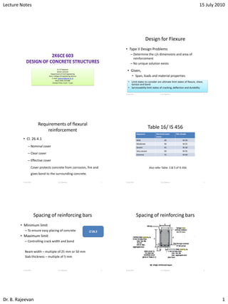
Design for Flexure
• Type II Design Problems
– Determine the c/s dimensions and area of
reinforcement
– No unique solution exists
15 July 2010 Dr. B. Rajeevan 2
• Given,
• Span, loads and material properties
• Limit states to consider are ultimate limit states of flexure, shear,
torsion and bond
• Serviceability limit states of cracking, deflection and durability
Requirements of flexural
reinforcement
• Cl. 26.4.1
– Nominal cover
– Clear cover
– Effective cover
Cover protects concrete from corrosion, fire and
gives bond to the surrounding concrete.
15 July 2010 Dr. B. Rajeevan 3
Table 16/ IS 456
15 July 2010 Dr. B. Rajeevan 4
Exposure Nominal cover
(mm)
Min Grade
Mild 20 M 20
Moderate 30 M 25
Severe 45 M 30
Very severe 50 M 35
Extreme 75 M 40
Also refer Table 3 & 5 of IS 456
Spacing of reinforcing bars
• Minimum limit
– To ensure easy placing of concrete
• Maximum limit
– Controlling crack width and bond
15 July 2010 Dr. B. Rajeevan 5
Beam width – multiple of 25 mm or 50 mm
Slab thickness – multiple of 5 mm
Spacing of reinforcing bars
15 July 2010 Dr. B. Rajeevan 6
2. Lecture Notes 15 July 2010
Dr. B. Rajeevan 2
Spacing of reinforcing bars
15 July 2010 Dr. B. Rajeevan 7
Spacing of reinforcing bars
15 July 2010 Dr. B. Rajeevan 8
16
Reinforcement - Beam
tension reinforcement
– To ensure crack control
– To take care of unforeseen loads
– To control shrinkage and temperature variations
15 July 2010 Dr. B. Rajeevan 9
,min 0.85
y
Ast
bd f
.26.5.1.1( )Cl a
Reinforcement - Beam
tension/compression
reinforcement
– To avoid congestion
15 July 2010 Dr. B. Rajeevan 10
,max 0.04stA bD
.26.5.1.1( )
.26.5.1.2
Cl b
Cl
Requirements- Slab
• Maximum diameter of bars (Cl. 26.5.2.2)
– Not greater than one eighth of the thickness of
slab.
– For crack control
• Minimum reinforcement (Cl. 26.5.2.1)
– 0.15bD
– 0.12bD for HYSD bars
15 July 2010 Dr. B. Rajeevan 11
Deflection Control
15 July 2010 Dr. B. Rajeevan 12
4
2
max
2
max 2 2 2
3
2
4
24
3
5
384
8
8 8 8
6
12
8
5
65
384
384
1
const
2
5
; conan stan
42
t t
w
EI
w
M
bD
w M Z
bD
I
bD
E b
D E
w
D
E
I
3. Lecture Notes 15 July 2010
Dr. B. Rajeevan 3
Codal provisions for deflection control
15 July 2010 Dr. B. Rajeevan 13
max
.23.2.1
ba
t c
sic
k k
d
Cl
d
7 cantilever
20 simplysupported
26 continuous
basicd
Refer Figs. 4 and 5 of code to get andt ck k
.22.2
/ distance between supports
clear span +
EffectiveSpan Cl
c c
smaller of
d
Selection of Member sizes
• Beams
– Placing of concrete
– Increase depth than width
• Provides better control of deflection and crack
15 July 2010 Dr. B. Rajeevan 14
,lim0.5 0.8
/ 1.5 2
200 ,250 300
230
/ 10 16
t tAssume p to p
D b to
Beamwidth mm mmand mm
Masonry wall mm
Span D to
Selection of Member sizes
• Slabs
– Based on deflection criteria
15 July 2010 Dr. B. Rajeevan 15
,lim0.4 0.5 1.25
/ 25
/ 32
415
t t tAssume p p k
d span ss slab
span continuous slab
Fe steel normallyused
clearcover + ( 5 10 )
2
D d round tonearest mmor mm
Design of singly reinforced rectangular
beams
15 July 2010 Dr. B. Rajeevan 16
,max
,lim2
0.87 1 , 1.1( )
100
Refer
1
6
00
1
yu t t
y t t
ck
u uR u uM M with
fM p p
R
x
f p p AnnexG b
bd f
x
SP
/ 8,
/ 25,
/ 32,
u
l cantilever
ss
continuous
M
d
Rb
Trial valuesof d beam
3
clearcover +
2
. 19.2.1 25 /
/ 1.5 2
clearco
,
ver
2
tie
tie
Exceedin
D d
Cl w kN m
D b g changebto
d D
Design Example
15 July 2010 Dr. B. Rajeevan 17
Solution
15 July 2010 Dr. B. Rajeevan 18
Inside beam – coastal are – Table 3, 5 & 16
Moderate exposure – clear cover = 30 mm and grade of concrete M25
Determine uM
250 ; 600 ( /10)
50 550
6
6 0.23 0.55 6.32
6
25 0.25 0.6 25 3.75 /
5 3.75 8.75 / ; 10 /
, 1.5 1.5 8.75 10 28.
Trialsection
.22
1
.2
DL LL
u DL LL
b mm D mm span
d D mm
m
m
m
s
Cl
elfweight bD kN m
w kN m w kN m
Factored l
Loads
oad w w w /kN m
4. Lecture Notes 15 July 2010
Dr. B. Rajeevan 4
15 July 2010 Dr. B. Rajeevan 19
2 2
,lim
26
min
lim ,lim
lim 2
/ 8 28.1 6 / 8 126
250
0.138
126 10
( )
3.45 250
0.138 3.45
382
382 3
Momen
6
t
0
,
1
,
u
u u
u
u ck
u
ck
M w kNm
Let b mm
M
Get from
M f bd
sameasinitially a
d
R b M
R f
M
Fixi
bd
mm
Then D
ng
ssumed
SP Tab
b
leC
d and D
Assuming 25 &
450 ( )
25
8 ( )
2
432.5 ( )
25
450 30 8 399
8
minimu
2
m
.5
m
mmdiabars mms
mm say
m
d m
tirrups
m
15 July 2010 Dr. B. Rajeevan 20
6
2 2
,
2
,
,
126 10
3.158
250 399.5
1.082 1.061
1.061 3.158 3.15 1.064
3.2 3.15
1062.67
100
1062.67
. 25 , 2.16
490.87
Provide1-25 +2-
3/ 16
95 / 16,
u
t
t
st reqd
st reqd
b
st reqd
M
bd
p
p
A
Table S
bd mm
A
No of mmbars n
A
P
Ta SP
A
ble
, ,
20
491 628 1119st prov st reqdA A
15 July 2010 Dr. B. Rajeevan 21
,
max
max
.4, 4
100 100 1119
1.12
250 399.5
228.4
1.014; 1
/ 1.014 1 20 20.28
/ 6000 / 399.5 15 /
5
,
6
st
t prov
s
t c
provided
DesignCheck for deflect
A
p
bd
f
k k
l d
l d
i
l d He
on
nce OK
Fig IS
15 July 2010 Dr. B. Rajeevan 22
Homework
15 July 2010 Dr. B. Rajeevan 23
Example 2
15 July 2010 Dr. B. Rajeevan 24
5. Lecture Notes 15 July 2010
Dr. B. Rajeevan 5
15 July 2010 Dr. B. Rajeevan 25
2 2
Moment,
4160
/ 25 4000 / 25 160
160 40 200
4000 230 4230
4000 160 4160
25 0.2 1 1 1 6 /
4 1 4 /
, 1.5 15 /
/ 8 15 4.16 / 8 32.45 /
D
u
L
LL
u DL LL
u u
Assumed span mm
D mm
mm
mm
w kN m
w kN m
Factored Load w w w kN m
M w kNm m
M
m
etrewid
m
thof slab
15 July 2010 Dr. B. Rajeevan 26
2
Moderateexposure 25
Main bars,
1.268; 3/ 16, 0.375
ck
u
t
st
f MPa
M
R Table SP p
bd
A
2
600 /
100
Using10 , , 100 131
. 3 3 160 480 300 300
Provide10
.26.3.3. (1)
@130 /
t
st
st
p bd
A mm metrewidthof slab
A
bars spacing s mm
A
Max Spacing Cd mmor mm m
m
m b
mc c
15 July 2010 Dr. B. Rajeevan 27
2
0.12 240 /
100
Using8 , , 100 209
. 5 5 160 800 450 45
Provide8 @200 /
.26.3.3. (2)0
st dist
st
bD
A mm metrewidthof slab
A
bars spacing s mm
A
M
Distributors
mmc cas distri
ax Spacing d mmor mm m
buto
Cm
r
b
s
2
,lim
200 30 10 / 2 165
1000 1000 78.54
604.15
130
10 ,0 0.37 1.1 69, 1
actual
st prov
prov
st prov
t t
Stre
d mm
A
A mm
ngthCheck
Detai
s
A
p p
b
Tab
ling
le
d
E SP
15 July 2010 Dr. B. Rajeevan 28
Design of Doubly Reinforced Beams
• Depth of beam is restricted, but moment is
higher
• Bending moment changes in sign
• To increase the ductility
• To reduce long term deflections due to
shrinkage and creep
15 July 2010 Dr. B. Rajeevan 29 15 July 2010 Dr. B. Rajeevan 30
6. Lecture Notes 15 July 2010
Dr. B. Rajeevan 6
15 July 2010 Dr. B. Rajeevan 31
/
0.0035 1cs
u
d
x
/
0.36 0.416
uc us
u uc c us s
u ck u u sc sc
C C C
M C z C z
M f bx d x f A d d
15 July 2010 Dr. B. Rajeevan 32
15 July 2010 Dr. B. Rajeevan 33
,lim 2
,lim ,max ,max 1
2 ,lim
/ 2
2 /
2
1
2
1 2
2
0.36 0.416 0.87
0.87
0.87
0.87
,
,
0.87
u u u
u ck u u y st
u u u
st
st
st
st s
u
u y st
y
y
t st
sc
sc
s
sc sc y st
M M M
M f bx d x f A
M M M
M
M f A d d
f
TensileSteel Area A
A
A
A A A
Compression Steel Area A
d d
f A
f A f A A
2t
scf
Example
• Design a doubly reinforced beam with the following
data to carry a factored moment of 1000 kNm
15 July 2010 Dr. B. Rajeevan 34
2 2 /
400 ; 550 ; 30 / ; 415 / ; 60ck yb mm d mm f N mm f N mm d mm
Solution
15 July 2010 Dr. B. Rajeevan 35
2
,lim 0.138
5
( / 16)
01
u ck TM f bd ableC
m
SP
kN
,lim
2
1
1.43
1.43
400 550 3146
100
( / 16)t
st
Table E SPp
A mm
2 ,lim
22
2 /
2
1 2
1000 501 499
2820.6
0.87
5967
u u u
u
st
y
st st st
M M M kNm
M
A mm
f d d
A A A mm
Solution
15 July 2010 Dr. B. Rajeevan 36
/
2
6
22
/
(
60 / 550 0.1
353 /
499 10
2885
353 550 60
6)
,
/ 1sc
u
sc
sc
sc
Tab
d
d
f N mm
M
A mm
f d d
Areaof Compression Steel A
le F SP
7. Lecture Notes 15 July 2010
Dr. B. Rajeevan 7
Solution by SP16
15 July 2010 Dr. B. Rajeevan 37
Homework
15 July 2010 Dr. B. Rajeevan 38
Design of Flanged Beams
15 July 2010 Dr. B. Rajeevan 39
T-beam under positive moment
15 July 2010 Dr. B. Rajeevan 40
T-beam under negative moment
15 July 2010 Dr. B. Rajeevan 41
L-beam under positive moment
15 July 2010 Dr. B. Rajeevan 42
8. Lecture Notes 15 July 2010
Dr. B. Rajeevan 8
L-beam under negative moment
15 July 2010 Dr. B. Rajeevan 43
Example – Design of T beam
15 July 2010 Dr. B. Rajeevan 44
Take Finish load = 1.72 kN/m2
Solution
15 July 2010 Dr. B. Rajeevan 45 15 July 2010 Dr. B. Rajeevan 46
15 July 2010 Dr. B. Rajeevan 47 15 July 2010 Dr. B. Rajeevan 48
9. Lecture Notes 15 July 2010
Dr. B. Rajeevan 9
15 July 2010 Dr. B. Rajeevan 49
RC SOILD SLAB
15 July 2010 Dr. B. Rajeevan 50
RC Solid Slab
1-way 2-way Flat Slab Flat Plate
15 July 2010 Dr. B. Rajeevan 51 15 July 2010 Dr. B. Rajeevan 52
DESIGN OF ONE WAY SLAB
15 July 2010 Dr. B. Rajeevan 53
Loads
• Self weight at 25 kN/m3 for reinforced concrete
• Finish and partition – 1.5 kN/m2
• Live load
– Based on usage
– Roof
• 1.5 kN/m2 for roof with access
• 0.75 kN/m2 for roof without access
– Floors
• 2 kN/m2 for residential floors
• 3 kN/m2 for office floors
15 July 2010 Dr. B. Rajeevan 54
10. Lecture Notes 15 July 2010
Dr. B. Rajeevan 10
One way slabs
15 July 2010 Dr. B. Rajeevan 55
Simply supported
Continuous
Simplified design using moment and shear coefficients
Tables 12 and 13
Moment and Shear Coefficients
15 July 2010 Dr. B. Rajeevan 56
Design Considerations
• Span to Effective depth ratio,
– Simply supported – 25
– Continuous – 30
• Concrete Cover
– Tables 3, 5 & 16
15 July 2010 Dr. B. Rajeevan 57
/ d
Design Considerations
• Calculation of steel area based on UR section
• Diameter of bar not to exceed 1/8th of thickens of
slab
• Steel area
• Spacing of main steel not greater than 3d or 300
mm
• Spacing of secondary steel not greater than 5d or
450 mm
15 July 2010 Dr. B. Rajeevan 58
0.87u y stM f A lever arm
0.12 ( 0.15 )stA bD or bD
Design Steps
– Design as beams of one metre width, with span as short dimension
– Assume depth based on deflection criteria
• Min depth 100 mm
– Determine factored loads. Compute factored moment and shear. Use
coefficients given in Table 7 for continuous one way slab
– Find effective depth required based on moment
– Add cover and find total depth of slab(thickness)
– Check for shear (k c) using Table 13 and Clause 39.2
– Revise depth, if necessary
– Determine
15 July 2010 Dr. B. Rajeevan 59
stA
Design Check
– Check for minimum percentage of steel
– Check for spacing
– Recheck for shear based on the actual steel
– Check for deflection
– Provide secondary reinforcement
– Detail
15 July 2010 Dr. B. Rajeevan 60
11. Lecture Notes 15 July 2010
Dr. B. Rajeevan 11
STRUCTURAL DETAIL
15 July 2010 Dr. B. Rajeevan 61 15 July 2010 Dr. B. Rajeevan 62
15 July 2010 Dr. B. Rajeevan 63 15 July 2010 Dr. B. Rajeevan 64
Design Example 1
15 July 2010 Dr. B. Rajeevan 65 15 July 2010 Dr. B. Rajeevan 66
12. Lecture Notes 15 July 2010
Dr. B. Rajeevan 12
15 July 2010 Dr. B. Rajeevan 67 15 July 2010 Dr. B. Rajeevan 68
15 July 2010 Dr. B. Rajeevan 69 15 July 2010 Dr. B. Rajeevan 70
15 July 2010 Dr. B. Rajeevan 71 15 July 2010 Dr. B. Rajeevan 72
Design Example 2
13. Lecture Notes 15 July 2010
Dr. B. Rajeevan 13
15 July 2010 Dr. B. Rajeevan 73 15 July 2010 Dr. B. Rajeevan 74
15 July 2010 Dr. B. Rajeevan 75 15 July 2010 Dr. B. Rajeevan 76
15 July 2010 Dr. B. Rajeevan 77 15 July 2010 Dr. B. Rajeevan 78
14. Lecture Notes 15 July 2010
Dr. B. Rajeevan 14
15 July 2010 Dr. B. Rajeevan 79 15 July 2010 Dr. B. Rajeevan 80