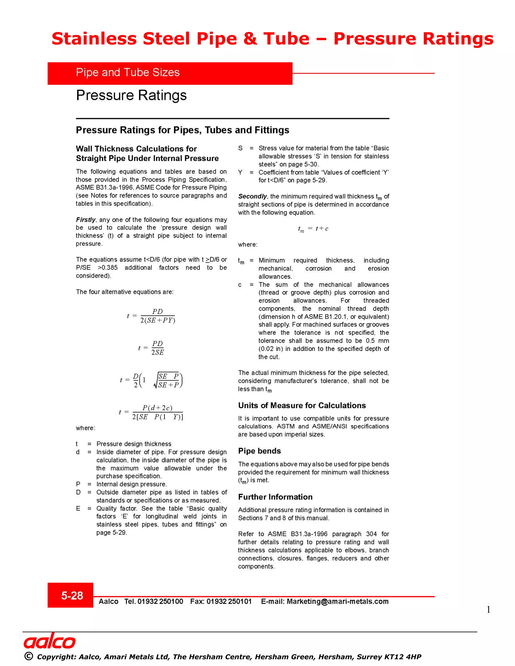
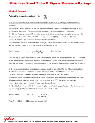
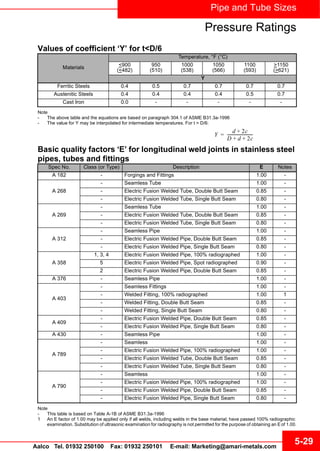
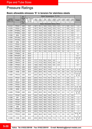
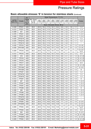
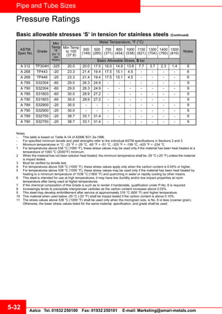
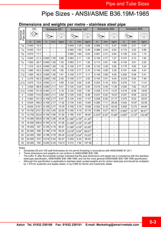
3. Pipe and Tube Sizes
5-29Aalco Tel. 01932 250100 Fax: 01932 250101 E-mail: Marketing@amari-metals.com
Pressure Ratings
Values of coefficient ‘Y’ for t<D/6
Note
- The above table and the equations are based on paragraph 304.1 of ASME B31.3a-1996
- The value for Y may be interpolated for intermediate temperatures. For t > D/6:
Basic quality factors ‘E’ for longitudinal weld joints in stainless steel
pipes, tubes and fittings
Note
- This table is based on Table A-1B of ASME B31.3a-1996
1 An E factor of 1.00 may be applied only if all welds, including welds in the base material, have passed 100% radiographic
examination. Substitution of ultrasonic examination for radiography is not permitted for the purpose of obtaining an Eof 1.00.
Materials
Temperature, °F (°C)
<900
(<482)
950
(510)
1000
(538)
1050
(566)
1100
(593)
>1150
(>621)
Y
Ferritic Steels 0.4 0.5 0.7 0.7 0.7 0.7
Austenitic Steels 0.4 0.4 0.4 0.4 0.5 0.7
Cast Iron 0.0 - - - - -
Y
d 2c
D d 2c
--------------------------
Spec No. Class (or Type) Description E Notes
A 182 - Forgings and Fittings 1.00 -
A 268
- Seamless Tube 1.00 -
- Electric Fusion Welded Tube, Double Butt Seam 0.85 -
- Electric Fusion Welded Tube, Single Butt Seam 0.80 -
A 269
- Seamless Tube 1.00 -
- Electric Fusion Welded Tube, Double Butt Seam 0.85 -
- Electric Fusion Welded Tube, Single Butt Seam 0.80 -
A 312
- Seamless Pipe 1.00 -
- Electric Fusion Welded Pipe, Double Butt Seam 0.85 -
- Electric Fusion Welded Pipe, Single Butt Seam 0.80 -
A 358
1, 3, 4 Electric Fusion Welded Pipe, 100% radiographed 1.00 -
5 Electric Fusion Welded Pipe, Spot radiographed 0.90 -
2 Electric Fusion Welded Pipe, Double Butt Seam 0.85 -
A 376 - Seamless Pipe 1.00 -
A 403
- Seamless Fittings 1.00 -
- Welded Fitting, 100% radiographed 1.00 1
- Welded Fitting, Double Butt Seam 0.85 -
- Welded Fitting, Single Butt Seam 0.80 -
A 409
- Electric Fusion Welded Pipe, Double Butt Seam 0.85 -
- Electric Fusion Welded Pipe, Single Butt Seam 0.80 -
A 430 - Seamless Pipe 1.00 -
A 789
- Seamless 1.00 -
- Electric Fusion Welded Pipe, 100% radiographed 1.00 -
- Electric Fusion Welded Tube, Double Butt Seam 0.85 -
- Electric Fusion Welded Tube, Single Butt Seam 0.80 -
A 790
- Seamless 1.00 -
- Electric Fusion Welded Pipe, 100% radiographed 1.00 -
- Electric Fusion Welded Pipe, Double Butt Seam 0.85 -
- Electric Fusion Welded Pipe, Single Butt Seam 0.80 -
6. 5-32
Pipe and Tube Sizes
Aalco Tel. 01932 250100 Fax: 01932 250101 E-mail: Marketing@amari-metals.com
Notes
- This table is based on Table A-1A of ASME B31.3a-1996.
- For specified minimum tensile and yield strengths refer to the individual ASTM specifications in Sections 2 and 3.
- Minimum temperatures in °C: -20 °F = -29 °C, -60 °F = -51 °C, -325 °F = -199 °C, -425 °F = -254 °C
1 For temperatures above 538 °C (1000 °F), these stress values may be used only if the material has been heat treated at a
temperature of 1093 °C (2000°F) minimum.
2 When the material has not been solution heat treated, the minimum temperature shall be -29 °C (-20 °F) unless the material
is impact tested.
3 Must be verified by tensile test.
4 For temperatures above 538 °C (1000 °F), these stress values apply only when the carbon content is 0.04% or higher.
5 For temperatures above 538 °C (1000 °F), these stress values may be used only if the material has been heat treated by
heating to a minimum temperature of 1038 °C (1900 °F) and quenching in water or rapidly cooling by other means.
6 This steel is intended for use at high temperatures; it may have low ductility and/or low impact properties at room
temperature after being used at higher temperatures.
7 If the chemical composition of this Grade is such as to render it hardenable, qualification under P-No. 6 is required.
8 Increasingly tends to precipitate intergranular carbides as the carbon content increases above 0.03%.
9 This steel may develop embrittlement after service at approximately 316 °C (600 °F) and higher temperature.
10 This material when used below -29 °C (-20 °F) shall be impact tested if the carbon content is above 0.10%.
11 The stress values above 538 °C (1000 °F) shall be used only when the micrograin size, is No. 6 or less (coarser grain).
Otherwise, the lower stress values listed for the same material, specification, and grade shall be used.
A 312 TP304H -325 20.0 20.0 17.5 16.0 14.9 13.8 7.7 3.7 2.3 1.4 8
A 268 TP443 -20 23.3 21.4 19.4 17.5 15.1 4.5 - - - - 6
A 268 TP446 -20 23.3 21.4 19.4 17.5 15.1 4.5 - - - - 6
A 789 S32304 -60 29.0 26.3 24.9 - - - - - - - 9
A 790 S32304 -60 29.0 26.3 24.9 - - - - - - - 9
A 789 S31803 -60 30.0 28.9 27.2 - - - - - - - 9
A 790 S31803 -60 30.0 28.9 27.2 - - - - - - 9
A 789 S32900 -20 30.0 - - - - - - - - - 9
A 790 S32900 -20 30.0 - - - - - - - - - 9
A 789 S32750 -20 38.7 33.1 31.4 - - - - - - - 9
A 790 S32750 -20 38.7 33.1 31.4 - - - - - - - 9
Basic allowable stresses ‘S’ in tension for stainless steels (Continued)
ASTM
Spec No. Grade
Min
Temp
°F
(for °C
see
Notes)
Metal Temperature, °F (°C)
Notes
Min Temp
to 100
(37.8)
300
(149)
500
(260)
700
(371)
850
(454)
1000
(538)
1150
(621)
1300
(704)
1400
(760)
1500
(816)
Basic Allowable Stress, S ksi
Pressure Ratings
7. Pipe and Tube Sizes
5-3Aalco Tel. 01932 250100 Fax: 01932 250101 E-mail: Marketing@amari-metals.com
Pipe Sizes - ANSI/ASME B36.19M-1985
Dimensions and weights per metre - stainless steel pipe
Notes
1 Schedules 5S and 10S wall thicknesses do not permit threading in accordance with ANSI/ASME B1.20.1.
2 These dimensions and weights do not conform to ANSI/ASME B36.10M.
- The suffix ‘S’ after the schedule number indicates that the pipe dimensions and weight are in compliance with this stainless
steel pipe specification, ANSI/ASME B36.19M-1985, and not the more general ANSI/ASME B36.10M-1995 specification.
- Although this specification is applicable to stainless steel, quoted weights are for carbon steel pipe and should be multiplied
by 1.014 for austenitic and duplex steels, or by 0.985 for ferritic and martensitic steels.
Nominal
PipeSize
OD 6FKHGXOH 6
6FKHGXOH 6 6FKHGXOH 6 6FKHGXOH 6
in mm in mm kg/m in mm kg/m in mm kg/m in mm kg/m
1
/8 0.405 10.3 - - - 0.049 1.24 0.28 0.068 1.73 0.37 0.095 2.41 0.47
1/4 0.540 13.7 - - - 0.065 1.65 0.49 0.088 2.24 0.63 0.119 3.02 0.80
3/8 0.675 17.1 - - - 0.065 1.65 0.63 0.091 2.31 0.84 0.126 3.20 1.10
1/2 0.840 21.3 0.065 1.65 0.80 0.083 2.11 1.00 0.109 2.77 1.27 0.147 3.73 1.62
3/4 1.050 26.7 0.065 1.65 1.03 0.083 2.11 1.28 0.113 2.87 1.69 0.154 3.91 2.20
1 1.315 33.4 0.065 1.65 1.30 0.109 2.77 2.09 0.133 3.38 2.50 0.179 4.55 3.24
11/4 1.660 42.2 0.065 1.65 1.65 0.109 2.77 2.70 0.140 3.56 3.39 0.191 4.85 4.47
11
/2 1.900 48.3 0.065 1.65 1.91 0.109 2.77 3.11 0.145 3.68 4.05 0.200 5.08 5.41
2 2.375 60.3 0.065 1.65 2.40 0.109 2.77 3.93 0.154 3.91 5.44 0.218 5.54 7.48
21
/2 2.875 73.0 0.083 2.11 3.69 0.120 3.05 5.26 0.203 5.16 8.63 0.276 7.01 11.41
3 3.500 88.9 0.083 2.11 4.51 0.120 3.05 6.45 0.216 5.49 11.29 0.300 7.62 15.27
31
/2 4.000 101.6 0.083 2.11 5.18 0.120 3.05 7.40 0.226 5.74 13.57 0.318 8.08 18.63
4 4.500 114.3 0.083 2.11 5.84 0.120 3.05 8.36 0.237 6.02 16.07 0.337 8.56 22.32
5 5.563 141.3 0.109 2.77 9.47 0.134 3.40 11.57 0.258 6.55 21.77 0.375 9.53 30.97
6 6.625 168.3 0.109 2.77 11.32 0.134 3.40 13.84 0.280 7.11 28.26 0.432 10.97 42.56
8 8.625 219.1 0.109 2.77 14.79 0.148 3.76 19.96 0.322 8.18 42.55 0.500 12.70 64.64
10 10.750 273.1 0.134 3.40 22.63 0.165 4.19 27.78 0.365 9.27 60.31 0.5002 12.702 96.012
12 12.750 323.9 0.156 3.96 31.25 0.180 4.57 36.00 0.3752 9.532 73.882 0.5002 12.702 132.082
14 14.000 355.6 0.156 3.96 34.36 0.1882
4.782
41.302 - - - - - -
16 16.000 406.4 0.165 4.19 41.56 0.1882 4.782 47.292 - - - - - -
18 18.000 457 0.165 4.19 46.81 0.1882
4.782
53.262 - - - - - -
20 20.000 508 0.188 4.78 59.25 0.2182 5.542 68.612 - - - - - -
22 22.000 559 0.188 4.78 65.24 0.2182 5.542 75.532 - - - - - -
24 24.000 610 0.218 5.54 82.47 0.250 6.35 94.45 - - - - - -
30 30.000 762 0.250 6.35 118.31 0.312 7.92 147.36 - - - - - -