
Recommended
More Related Content
What's hot
What's hot (20)
Similar to Heat Transfer Homework Problems
Similar to Heat Transfer Homework Problems (20)
More from semihypocrite
More from semihypocrite (10)
Recently uploaded
Recently uploaded (20)
Heat Transfer Homework Problems
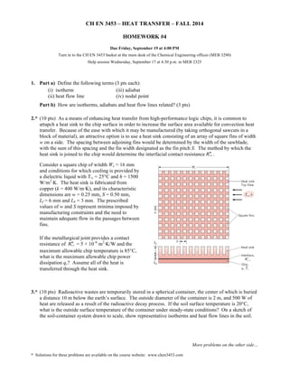
- 1. CH EN 3453 – HEAT TRANSFER – FALL 2014 Turn in to the CH EN 3453 basket at the main desk of the Chemical Engineering offices (MEB 3290) Help session Wednesday, September 17 at 4:30 p.m. in MEB 2325 2.* (10 pts) As a means of enhancing heat transfer from high-performance logic chips, it is common to attapch a heat sink to the chip surface in order to increase the surface area available for convection heat transfer. Because of the ease with which it may be manufactured (by taking orthogonal sawcuts in a block of material), an attractive option is to use a heat sink consisting of an array of square fins of width w on a side. The spacing between adjoining fins would be determined by the width of the sawblade, with the sum of this spacing and the fin width designated as the fin pitch S. The method by which the heat sink is joined to the chip would determine the interfacial contact resistance Rt′,′c . Consider a square chip of witdth Wc = 16 mm and conditions for which cooling is provided by a dielectric liquid with T∞ = 25°C and h = 1500 W/m2·K. The heat sink is fabricated from copper (k = 400 W/m·K), and its characteristic dimensions are w = 0.25 mm, S = 0.50 mm, Lf = 6 mm and Lb = 3 mm. The prescribed values of w and S represent minima imposed by manufacturing constraints and the need to maintain adequate flow in the passages between fins. 3.* (10 pts) Radioactive wastes are temporarily stored in a spherical container, the center of which is buried a distance 10 m below the earth’s surface. The outside diameter of the container is 2 m, and 500 W of heat are released as a result of the radioactive decay process. If the soil surface temperature is 20°C, what is the outside surface temperature of the container under steady-state conditions? On a sketch of the soil-container system drawn to scale, show representative isotherms and heat flow lines in the soil. More problems on the other side… HOMEWORK #4 Due Friday, September 19 at 4:00 PM 1. Part a) Define the following terms (3 pts each): (i) isotherm (iii) adiabat (ii) heat flow line (iv) nodal point Part b) How are isotherms, adiabats and heat flow lines related? (3 pts) If the metallurgical joint provides a contact resistance of Rt′,′c = 5 × 10⁻⁶ m2·K/W and the maximum allowable chip temperature is 85°C, what is the maximum allowable chip power dissipation qc? Assume all of the heat is transferred through the heat sink. * Solutions for these problems are available on the course website: www.chen3453.com
- 2. 4.* (10 pts) An igloo is built in the shape of a hemisphere, with an inner radius of 1.8 m and walls of compacted snow that are 0.5 m thick. On the inside of the igloo the surface heat transfer coefficient is 6 W/m2·K; on the outside, under normal conditions, it is 15 W/m2·K. The thermal conductivity of compacted snow is 0.15 W/m·K. The temperature of the ice cap on which the igloo sits is –20°C and has the same thermal conductivity as the compacted snow. Assuming that the occupants’ body heat provides a continuous source of 320 W within the igloo, calculate the inside air temperature when the outside air temperature is T∞ = –40°C. Be sure to consider heat losses through the floor of the igloo. 5.* (10 pts) Steady-state temperatures (K) at three nodal points of a long rectangular rod are shown. The rod experiences a uniform volumetric energy generation rate of 5 × 10⁷ W/m3 and has a thermal conductivity of 20 W/m·K. Two of its sides are maintained at a constant temperature of 300 K, while the others are insulated. (a) Determine the temperatures at nodes 1, 2 and 3. (b) Calculate the heat transfer length per unit length (W/m) from the rod using the nodal temperatures. Compare this result with the heat rate calculated from knowledge of the volumetric generation rate and rod dimensions. 6. (5 pts) For the geometry shown to the right, sketch isotherms and heat flow lines. (See supplemental material for chapter 4 on the book’s companion web site. A link to the companion site is on the “miscellaneous” pages of the CH EN 3453 web site.) 7. (20 pts) The engine of my go-cart has circular fins, 3 mm thick, that are machined into the aluminum of the cylinder (k = 240 W/m·K) such that the outer diameter of the cylinder itself (not including the fins) is 10 cm and the fins stick out from the cylinder by 5 cm. The temperature of the cylinder cannot exceed 265°C. I typically run my go-cart in on a 27°C day under conditions such that the convective heat transfer coefficient h is 80 W/m2·K. (a) Estimate the amount of heat transferred by a single fin. (b) If the engine is 8.5 kW in size, is 30% efficient in transferring power (the other 70% is lost as heat) and 80% of the lost heat is transferred by the fins, how many fins are needed? 8. (20 pts) The outside wall surface of a 25 mm diameter metal tube (k = 42 W/m·K) is maintained at 120°C. The tube is located in a room at 25°C and the convective heat transfer coefficient is 34 W/m2·K. We’d like to increase heat transfer from the tube by adding fins that are 3 mm thick and 18 mm long, made of the same material as the tube. What will be the percentage increase in heat transfer if we add the following types of fins? (a) Twelve straight fins positioned longitudinally parallel to the axis of the tube (b) Circular fins having the same total surface area as the twelve fins in case (a) * Solutions for these problems are available on the course website: www.chen3453.com Hot Cold