
Recommended
More Related Content
What's hot
What's hot (20)
Viewers also liked
Similar to Elect principles 2 three phase systems
Similar to Elect principles 2 three phase systems (20)
More from sdacey
More from sdacey (20)
Recently uploaded
Recently uploaded (20)
Elect principles 2 three phase systems
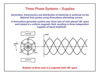
- 1. Three Phase Systems – Supplies Generation, transmission and distribution of electricity is achieved via the National Grid system using three-phase alternating current. A three-phase generator system uses three sets of coils placed 120˚ apart and rotated in a uniform magnetic field, resulting in three independent supplies of equal amplitude. Rotation of three coils in a magnetic field 120° apart.
- 2. Star connected balanced load IL = IP VL = 3 x VP Three Phase Systems – Star Connection The advantage of star connection is that two voltages become available Line voltage Phase Voltage Line voltage is sent across the National Grid system Phase Voltage is the voltage used in domestic supplies (homes, offices etc)
- 3. Three Phase Systems – Delta Connection To obtain greater power efficiency most three phase motors are operated in delta. To prevent large starting current these motors are initially connected in star then once up to speed they are connected in delta (star/delta starter). VL = VP IL = 3 x IP Delta connected balanced load VL VL IL IL IL VL
- 4. Three Phase Systems – Power Line voltage is sent across the National Grid system Phase Voltage is the voltage used in domestic supplies (homes, offices etc) and is the line voltage with respect to neutral. Power in a single phase system is given by; Power = VI cos θ (W) In a balanced three-phase system total power is; Total three phase Power = 3VP IP cos θ (W) For a star or delta connected system; Total three-phase power = 3 VLIL cos θ (W)
- 5. Three identical loads each having an impedance of 22 ohms are connected first in star and then in delta across a 415V 50Hz supply. Calculate the line and phase current in each case. Three Phase Systems – Power Distribution For Star connection .9.10 22 240 240 3 415 3 AII Z V II V V V PL L PL L P == === === For Delta connection .67.3286.183 3 .86.18 22 415 415 A II A Z V I VVV PL P P PL =×= = === ==
- 6. Three Phase Systems – Power Distribution Electricity Boards National Grid 400,000 V 400,000/132,000 V 132,000/33,000V 33,000/11,000 V 11,000/415/240 V Transformer Grid System Transformer Transformer Transformer Generation, transmission and Distribution of Electricity Generating Companies National Power Power Gen Nuclear Electric French Electric Scottish Electric
- 7. Three Phase Systems Activity 1. A balanced star-connected three-phase load of 10 ohms per phase operates from a 400V supply at a power factor of 0.9. Calculate a) phase voltage, b) line current and c) total power consumed. 2. A balanced load having an inductive reactance of 15Ω and resistance 5Ω is connected first in star then in delta to a 415V three-phase supply. Calculate the line and phase current in each case. 3. A 15kW, 415V, balanced three-phase star connected load has a power factor of 0.86 lagging. Determine the line current.
- 8. Three Phase Systems – Summary For a Star connected system, IL = IP VL = 3 x VP • For a Delta connected system VL = VP IL = 3 x IP • For a star or delta connected system; Total three-phase power, P = 3 VL IL cosθ (W)