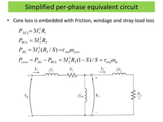
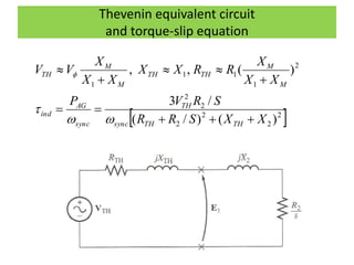
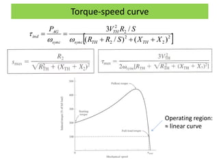
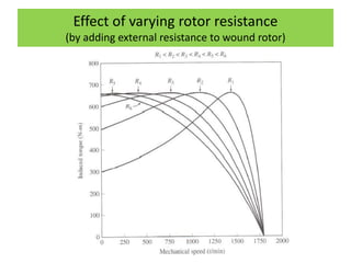
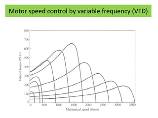
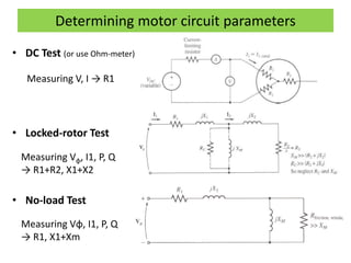
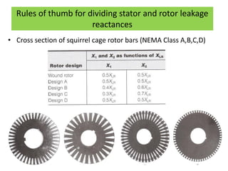
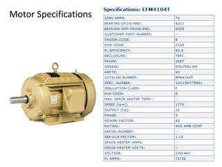
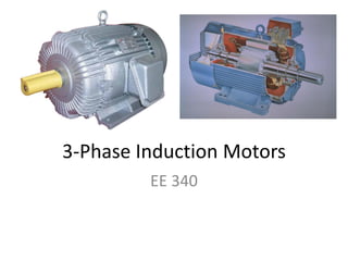
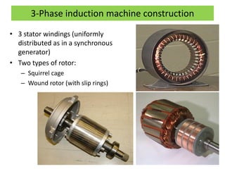
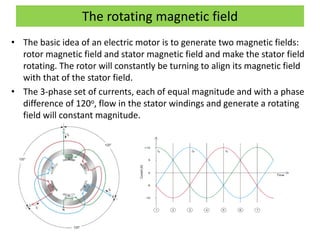
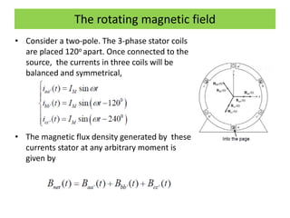
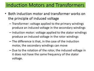
3-Phase Induction Motors
EE 340
Where does the power go?
• The electric energy generated purchased by
consumers for different needs. This energy is
converted to different forms:
– Lighting (indoor/outdoor – CFL, incandescent,
LED, Halogen…)
– Heating (electric water heaters, clothes dryers,
electric stoves and ovens)
– power supply of electronic devices (computers,
TV, DVD, battery chargers, home automation,
etc…)
– Industrial (arc furnaces, welders, manufacturing
processes….)
– Conversion to mechanical power by motors
(pumps, fans, HVAC, refrigeration – compressors,
power tools, food processors, escalators,
elevators, ….)
Types of Electric Motors
3-Phase induction machine construction
• 3 stator windings (uniformly
distributed as in a synchronous
generator)
• Two types of rotor:
– Squirrel cage
– Wound rotor (with slip rings)
The rotating magnetic field
• The basic idea of an electric motor is to generate two magnetic fields:
rotor magnetic field and stator magnetic field and make the stator field
rotating. The rotor will constantly be turning to align its magnetic field
with that of the stator field.
• The 3-phase set of currents, each of equal magnitude and with a phase
difference of 120o, flow in the stator windings and generate a rotating
field will constant magnitude.
The rotating magnetic field
• Consider a two-pole. The 3-phase stator coils
are placed 120o apart. Once connected to the
source, the currents in three coils will be
balanced and symmetrical,
• The magnetic flux density generated by these
currents stator at any arbitrary moment is
given by
The rotating magnetic field
• The net magnetic field has a constant magnitude and rotates
counterclockwise at the angular velocity ω.
• The stator rotating magnetic field can be represented by a
spinning magnet.
• For a two pole machine,
• For a p-pole machine,
)(
60
1
)()( rpmnrpsfHzf sme 
)(
120
)(
2
)( rpmn
p
rpsf
p
Hzf sme 
Principle of Operation
• https://www.electrical4u.com/working-
principle-of-three-phase-induction-motor/
Per-phase equivalent circuit
• Motor Slip
• R1 and R2: stator and rotor winding resistances
• X1 and X2: stator and rotor winding leakage reactances
• Xm: magnetizing reactance
• Rc: core loss resistance
• Rotor winding parameters are referred to the stator side
s
ms
n
nn
s


Power flow diagram
]/)1([3
3
)/(3
/3
3
2
2
2
2
2
2
2
2
2
2
1
1
2
1
SSRIPPP
RIP
SRIP
REp
RIP
RCLAGconv
RCL
AG
Ccore
SCL





Simplified per-phase equivalent circuit
• Core loss is embedded with friction, windage and stray-load loss
mindRCLAGconv
syncindAG
RCL
SCL
SSRIPPP
SRIP
RIP
RIP






/)1(3
)/(3
3
3
2
2
2
2
2
2
2
2
2
1
2
1
Thevenin equivalent circuit
and torque-slip equation
 2
2
2
2
2
2
2
1
11
1
)()/(
/3
)(,,
XXSRR
SRVP
XX
X
RRXX
XX
X
VV
THTHsync
TH
sync
AG
ind
M
M
THTH
M
M
TH









Torque-speed curve
 2
2
2
2
2
2
)()/(
/3
XXSRR
SRVP
THTHsync
TH
sync
AG
ind




Operating region:
≈ linear curve
Effect of varying rotor resistance
(by adding external resistance to wound rotor)
Motor speed control by variable frequency (VFD)
Determining motor circuit parameters
• DC Test (or use Ohm-meter)
• Locked-rotor Test
• No-load Test
Measuring Vφ, I1, P, Q
→ R1+R2, X1+X2
Measuring V, I → R1
Measuring Vφ, I1, P, Q
→ R1, X1+Xm
Rules of thumb for dividing stator and rotor leakage
reactances
• Cross section of squirrel cage rotor bars (NEMA Class A,B,C,D)
Motor Specifications
Problems
• 7.4
• 7.5
• 7.7*, 7.8, 7.10
• 7.14, 7.15
• 7.18
• 7.19

Induction motors

  • 1.
  • 2.
    Where does thepower go? • The electric energy generated purchased by consumers for different needs. This energy is converted to different forms: – Lighting (indoor/outdoor – CFL, incandescent, LED, Halogen…) – Heating (electric water heaters, clothes dryers, electric stoves and ovens) – power supply of electronic devices (computers, TV, DVD, battery chargers, home automation, etc…) – Industrial (arc furnaces, welders, manufacturing processes….) – Conversion to mechanical power by motors (pumps, fans, HVAC, refrigeration – compressors, power tools, food processors, escalators, elevators, ….)
  • 3.
  • 4.
    3-Phase induction machineconstruction • 3 stator windings (uniformly distributed as in a synchronous generator) • Two types of rotor: – Squirrel cage – Wound rotor (with slip rings)
  • 5.
    The rotating magneticfield • The basic idea of an electric motor is to generate two magnetic fields: rotor magnetic field and stator magnetic field and make the stator field rotating. The rotor will constantly be turning to align its magnetic field with that of the stator field. • The 3-phase set of currents, each of equal magnitude and with a phase difference of 120o, flow in the stator windings and generate a rotating field will constant magnitude.
  • 7.
    The rotating magneticfield • Consider a two-pole. The 3-phase stator coils are placed 120o apart. Once connected to the source, the currents in three coils will be balanced and symmetrical, • The magnetic flux density generated by these currents stator at any arbitrary moment is given by
  • 8.
    The rotating magneticfield • The net magnetic field has a constant magnitude and rotates counterclockwise at the angular velocity ω. • The stator rotating magnetic field can be represented by a spinning magnet. • For a two pole machine, • For a p-pole machine, )( 60 1 )()( rpmnrpsfHzf sme  )( 120 )( 2 )( rpmn p rpsf p Hzf sme 
  • 9.
    Principle of Operation •https://www.electrical4u.com/working- principle-of-three-phase-induction-motor/
  • 16.
    Per-phase equivalent circuit •Motor Slip • R1 and R2: stator and rotor winding resistances • X1 and X2: stator and rotor winding leakage reactances • Xm: magnetizing reactance • Rc: core loss resistance • Rotor winding parameters are referred to the stator side s ms n nn s  
  • 17.
  • 18.
    Simplified per-phase equivalentcircuit • Core loss is embedded with friction, windage and stray-load loss mindRCLAGconv syncindAG RCL SCL SSRIPPP SRIP RIP RIP       /)1(3 )/(3 3 3 2 2 2 2 2 2 2 2 2 1 2 1
  • 19.
    Thevenin equivalent circuit andtorque-slip equation  2 2 2 2 2 2 2 1 11 1 )()/( /3 )(,, XXSRR SRVP XX X RRXX XX X VV THTHsync TH sync AG ind M M THTH M M TH         
  • 20.
  • 21.
    Effect of varyingrotor resistance (by adding external resistance to wound rotor)
  • 22.
    Motor speed controlby variable frequency (VFD)
  • 23.
    Determining motor circuitparameters • DC Test (or use Ohm-meter) • Locked-rotor Test • No-load Test Measuring Vφ, I1, P, Q → R1+R2, X1+X2 Measuring V, I → R1 Measuring Vφ, I1, P, Q → R1, X1+Xm
  • 24.
    Rules of thumbfor dividing stator and rotor leakage reactances • Cross section of squirrel cage rotor bars (NEMA Class A,B,C,D)
  • 25.
  • 26.
    Problems • 7.4 • 7.5 •7.7*, 7.8, 7.10 • 7.14, 7.15 • 7.18 • 7.19