Calculation Efficiency of 5GW Hydropower Plant.
•Download as DOCX, PDF•
0 likes•398 views

Calculation Efficiency of 5GW Hydropower Plant.

Recommended
More Related Content
What's hot
What's hot (20)
Similar to Calculation Efficiency of 5GW Hydropower Plant.
Similar to Calculation Efficiency of 5GW Hydropower Plant. (20)
More from Salman Jailani
More from Salman Jailani (20)
Recently uploaded
Recently uploaded (20)
Calculation Efficiency of 5GW Hydropower Plant.
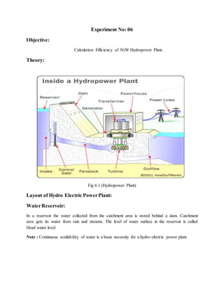
- 1. Experiment No: 06 Objective: Calculation Efficiency of 5GW Hydropower Plant. Theory: Fig 6.1 (Hydropower Plant) Layout of Hydro Electric PowerPlant: WaterReservoir: In a reservoir the water collected from the catchment area is stored behind a dam. Catchment area gets its water from rain and streams. The level of water surface in the reservoir is called Head water level. Note : Continuous availability of water is a basic necessity for a hydro-electric power plant.
- 2. Dam: The purpose of the dam is to store the water and to regulate the out going flow of water. The dam helps to store all the incoming water. It also helps to increase the head of the water. In order to generate a required quantity of power it is necessary that a sufficient head is available. Spillway: Excess accumulation of water endangers the stability of dam construction. Also in order to avoid the over flow of water out of the dam especially during rainy seasons spillways are provided. This prevents the rise of water level in the dam.Spillways are passages which allows the excess water to flow to a storage area away from the dam. Gate: A gate is used to regulate or control the flow of water from the dam. Pressure Tunnel: It is a passage that carries water from the reservoir to the surge tank. Surge Tank: A Surge tank is a small reservoir or tank in which the water level rises or falls due to sudden changes in pressure. Purpose of Surge Tank: To serve as a supply tank to the turbine when the water in the pipe is accelerated during increased load conditions and as a storage tank when the water is decelerating during reduced load conditions.To reduce the distance between the free water surface in the dam and the turbine, thereby reducing the water-hammer effect on penstock and also protect the upstream tunnel from high pressure rise. Water-Hammer Effect: The water hammer is defined as the change in pressure rapidly above or below normal pressure caused by sudden change in the rate of water flow through the pipe, according to the demand of prime mover i.e. turbine. Penstock: Penstock is a closed pipe of steel or concrete for supplying water under pressure to the turbine.
- 3. Inlet Valve: Water from the penstock flows to the turbine through the inlet valve. The valve may be partially closed or open thereby regulating the pressure of water flowing to the turbine. Hydraulic Turbine (Prime Mover) : The hydraulic turbine converts the energy of water into mechanical energy. The mechanical energy(rotation) available on the turbine shaft is coupled to the shaft of an electric generator and electricity is produced. The water after performing the work on turbine blades is discharged through the draft tube.The prime movers which are in common use are Pelton wheel, Francis turbine and Kaplan turbine. Draft Tube: It is connected to the outlet of the turbine.It allows the turbine to be placed above the tail water level. Tail Water Level or Tail Race: Tail water level is the water level after the discharge from the turbine. The discharged water is sent to the river, thus the level of the river is the tail water level. Electric Generator, Step-Up Transformer And Pylon : As the water rushes through the turbine, it spins the turbine shaft, which is coupled to the electric generator. The generator has a rotating electromagnet called a rotor and a stationary part called a stator. The rotor creates a magnetic field that produces an electric charge in the stator. The charge is transmitted as electricity. The step-up transformer increases the voltage of the current coming from the stator. The electricity is distributed through power lines also called as pylon. Working: Potential energy is the energy which a substance has due to its position or state. The water behind a dam has potential energy because of its position. The water can fall from this position and exert a force over a distance and therefore do work. In a Hydro-electric power plant the force is used to drive a turbine, which inturn drives the electric generator. Because gravity provides the force which makes the water fall, the energy stored in the water is called gravitational potential energy. Classification of Hydro Electric Power Plants: Hydro –electric power plants are usually classified according to the available head of water.
- 4. High Head Power Plants: Head of water is more than 500 metres. The turbine used in such plants is Pelton wheel. Medium Head Power Plants: Head of water ranges from 80 to 500 metres. The turbine used in such plants is Francis turbine. Low Head Power Plants: Head of water ranges from 1.5 to 80 metres. The turbine used in such plants is Kaplan turbine and Francis turbine. Advantages of Hydel Power Plant: 1. Water is a renewable energy source. 2. Maintenance and operation charges are very low. 3. The efficiency of the plant does not change with age. 4. In addition to power generation, hydro-electric power plants are also useful for flood control, irrigation purposes, fishery and recreation. 5. Have a longer life(100 to 125 years) as they operate at atmospheric temperature. 6. Water stored in the hydro-electric power plants can also be used for domestic water supply. 7. Since hydro-electric power plants run at low speeds(300 to 400 rpm) there is no requirement of special alloy steel construction materials or specialised mechanical maintenance. DisadvantagesofHydel PowerPlant: 1. The initial cost of the plant is very high. 2. Since they are located far away from the load centre, cost of transmission lines and transmission losses will be more. 3. During drought season the power production may be reduced or even stopped due to insufficient water in the reservoir. 4. Water in the reservoir is lost by evaporation. Hydropower is very efficient: Efficiency = 𝐸𝑙𝑒𝑐𝑡𝑟𝑖𝑐 𝑝𝑜𝑤𝑒𝑟 𝑑𝑒𝑙𝑖𝑣𝑒𝑟 𝑡𝑜 𝑡ℎ𝑒 𝑏𝑢𝑠𝑏𝑎𝑟 𝑝𝑜𝑡𝑒𝑛𝑡𝑖𝑎𝑙 𝑒𝑛𝑒𝑟𝑔𝑦 𝑡𝑜 ℎ𝑒𝑎𝑑 𝑤𝑎𝑡𝑒𝑟 Typical Losses Are Due To: 1. Frictional drag and turbulence of flow 2. Friction and magnetic losses in turbine & generator 3. Overall efficiency ranges from 75-95%
- 5. P = G x ηx Q xH P = 9.81 x η x Q x H Where: P = power in kilowatts (kW) g = gravitational acceleration (9.81 m/s2) = turbo-generator efficiency (0<n<1) Q = quantity of water flowing (m3/sec) H = effective head (m) Calculation: P ≈ 10 ≈ QH = 10(0.83)(6000)(100) P ≈ 4.98 million kW = 4.98 GW (gigawatts) Comments: 1. It is very important remember that the work also Hydropower is very efficient. 2. We learn about power plant calculations.