TataKelola dan KamSiber Kecerdasan Buatan v022.pdf
Lesson02
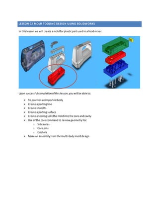
1. LESSON 02 MOLD TOOLING DESIGN USING SOLIDWORKS
In thislessonwe will create amoldforplasticpartusedin a foodmixer.
Upon successful completionof thislesson,youwill be able to:
To positionanimportedbody
Create a partingline
Create shutoffs
Create a partingsurface
Create a toolingsplit the moldintothe core andcavity
Use of the core commandto review geometryfor:
o Side cores
o Core pins
o Ejectors
Make an assemblyfromthe multi-bodymolddesign
2. OPENING A PART
TO OPEN THE PART:
Browse to C:MoldToolDie101Lesson02 Class_Example_Part.x_b andDouble Clicktoopenthe part in
SolidWorks
Notnecessaryto runimportdiagnosticsonthe
part but on a real customerpart itis
recommendtorun thisto fix anygaps and
errors.
SELECTING A UNIT SYSTEM
TO SELECT A UNIT SYSTEM:
1. Clickon Tools> Options> Document
options> Units> MMGS
2. You can alsochange thisfromthe Status
bar as showninthe right.
3. POSITION THE PART
Typical parts formold tool designare importedfrom3rd
party CAD systems;oftenthe partisnot
orientedcorrectlyforthe desiredtoolingtobe created.Thisisachievedusingthe Move/CopyBody
command
TO POSITION A PART:
1. Clickon Insert> Feature > Move/Copy…
2. Selectthe body.
3. Expandup the Rotate group inthe
PropertyManager. Observe the Triadon
the screen.
4. Mouse overthe blue Zaxisrotationring
5. Drag withthe LMB (LeftMouse Button)
and thiswill rotate the part
6. Type -180 intothe X-axistogeta precise
position
7. ClickOKto close the command.
Before Rotation AfterRotation
This commandcan alsopositionthe partin X,Y,Z by draggingwiththe LMB and itcan make copies
of the body
4. APPLY SHRINKAGE
Plasticmoldedpartswill shrinkwhentheyeject fromthe moldandcool to room temperature.Sowe
needtobuildthe moldto be slightlybiggerthanthe actual part so whenthe part shrinkswe getthe
rightdimensionpart.
TO APPLY SHRIKAGE:
1. Clickon Insert> Molds> Scale
2. Use Centroid
3. Check Uniformscaling
4. Enter a scalingvalue of 1.066
5. ClickOK
5. PERFORMING DRAFT ANALYSIS
An appropriate draftangle will aideinthe removal of the partfromthe mold.Withoutthe properdraft
angle partsmay become hungup or stuckuponejectionandmold damage mayoccur. Be sure there are
draft anglesonall bosses,ribs,andnominal walls.
TO REVIEW DRAFT ANGLES ON PART:
1. Click on View> Display > Draft Analysis
2. Selectaplanar face that isparallel tothe
partingplane
3. Selectthe draftangle thatyou require e.g.
1.5 degrees
4. Enable the checkbox forface classification
The variousmodel facesare nowcoloured
accordingto theirdraft angle,the numbersof
facesineach classificationare shown
Using the buttonyoucan hide and
showindividualclassesof faces
You can alsochange theircolourusingthe
button
Exitingthe commandwiththe buttonwill
leave the analysisactive soyoucan:
You can thencorrect any erroneousdraft
Watchingthe resultschange
6. CREATE PARTING LINES
Thisis usedtoestimate andselectapartingline basedonthe boundarybetweenpositive andnegative
draft of the mold.
TO CREATE A PARTING LINE:
1. Click on Insert> Molds> Parting Line
2. Rotate the part sothe partingline isatthe top.Select
a plane e.g.the top of one of the bosses
3. Clickthe Draft Analysisbutton
4. The systemautomaticallyselectsthe correctparting
line,showninblue
5. ClickOK.
Selecting partline line edges
You can press Y instead of Add selected edge
You can press N instead of Select next edge
7. CREATE SHUT-OFF SURFACES
Create shut-off surfaces to fill holes in the core and cavity.
TO CREATE SHUT-OFF SURFACES:
1. Clickon Insert> Molds> Shut-OffSurfaces.
Basedon the previouslycreatedPartingLine
feature,the draftangle transitionsandopen
loops(holes),the systemwill trytoauto select
the loopsthat needtobe filled.Show the
previewtosee if anysurfacesare not selected.
2. Selectthe ventilationloopsinthe righthandof
the part usingany of these techniques:
a. Zoomin tight,change to wire frame
hidden
b. RMB > SelectTangency overan edge
c. RMB > SelectLoop overan edge
d. Pickan edge andselectthe cyan
propagationicon selectthe
to selectthe lastedge andfinish
the loop
e. Repeatstepd forotherslotsas well.
Pickeach edge one at a time
8. 3. Selectthe ventilationloopsinthe lefthandof
the part.
a. Zoomin tight,change to a wire frame
viewandturn off preview
b. Pickone of the circularedgesat the top
of eachventand pressthe button
to propagate the selectionaroundthe
loop
c. Repeatforeach of the ventsinturn
4. Create the telescopicshutoffforthe complex
hole:
a. Zoomin tight
b. Enable the preview checkbox
c. Change the patch type to Tangent
d. The can thenbe flippedto
create the telescopicshut-off inthe
desireddirection
e. The message shouldnow be green
5. Exitthe command
It’s a goodideato keepthe previewcheckbox turnedoff forperformance reasons,especiallyif there
are contact patchesthat the systemcan’tcreate
9. CORE AND CAVITY SURFACES
Whenthe user exitsthe PartingLine orShut-Off
commandwitha greenmessage pane,the system
will create the core and cavitysurface sets:
• Foldersare createdat the top of the FM
• One for the cavitysurface
• One for the core surfaces
The contentsof the folderhierarchiescanbe setat
each level:
• Show/hide
• Have theirappearance set
There is a checkbox onthe Partingline and
Shut-Off surface PMto disable knittingof the
surfaces
If youmanuallybuildthe shut-off surfaces,
usershouldmanuallycreate the surface andputa
copy inthe core and the cavitysurfacesfolders
10. CREATE PARTING SURFACE
Create a partingsurface to splitthe moldblockincombinationwiththe core andcavitysurfaces.
Usuallythisisbasedon the firstpartingline feature inthe part,thisalsosuppliesthe pulldirectionto
the command
The Partingsurface may be created withthe
followingprocedure:
1. ClickInsert> Molds> Parting Surface
2. SetPerpendicularto pull for Mold
parameters
3. Enter 37.5mm for Distance
4. ClickOK to create partingsurface.
11. CREATE TOOLING SPLIT
Use toolingsplitto create the core and cavity mold blocks.
1. Click Insert > Molds > Tooling split
2. The system will prompt you to selecta planeor
planar faceto sketch the cross section of the
mold blocks on.in this casewe can use the
partingsurfacebecauseit is planarand in the
correct location.
3. Sketch the outlineof the mold blocks,such
that the sketch fits insidethe boundaries of the
partingsurface
4. Enter 25.00 mm for Depth in direction1.
5. Enter 50.00 mm for Depth in direction2.
6. Exit the sketch and the system will activatethe
ToolingSplitcommands own Property
Manager
12. SEEING INSIDE THE MOLD BLOCKS
Nowthat we have the core and cavityblockswe needtomove themapart so we can workon creating
cores,ejectorsetc. Use the followingprocedure.
1. Clickthe ConfigurationManager.
2. RMB Defaultand selectNewExplodedView
3. Move bodiestosee the core,cavityandpart.
4. ClickOK.
5. Collapse the explodedview
13. SIDE CORES, LIFTERS, INSERTS, CORE PINS AND EJECTOR PINS
Variouspiecesof geometry‘cores’ are extractedfromthe core andcavity bodiestoassistinmodelling:
Side Cores
Lifters
Inserts
Core pins
Ejectorpins
1. Thisis achievedbycreatingasketchon an appropriate planarface or plane thatdefinesthe
outline of the core
2. Thisis thenextrudedthroughthe moldblockcuttingoutasolidwhichcan thenbe usedto
model the retractor insertpiece forthe mold
3. The user can add draftin the pull direction,foraside core by includingitintheirsketch of the
core profile
4. Draft inthe retractdirectionforthe side core is addedinthe core command
Due to lack of time we will review the partwhichcontainsthese features.
Browse to C:MoldToolDie101Lesson02BuiltPartsClass_Example_Part_completed.sldprt and
Double Clicktoopenthe part inSolidWorks.Review how the followingfeatureswerecreated:
Cores,ejectorpinsandcore pins
Save bodiesfeature tosave thisasa sub-asssembly
SAVING AND CLOSE ALL THE FILES
Congratulations! Aftercompletingthistutorial,younow have the basicskillsrequiredto create abasic
moldbase for yourplasticpart.