
Recommended
More Related Content
What's hot
What's hot (20)
Similar to thick cylinder
Similar to thick cylinder (20)
Recently uploaded
Recently uploaded (20)
thick cylinder
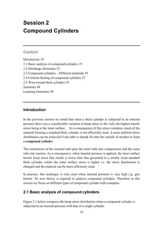
- 1. 19 Session 2 Compound Cylinders Content Introduction 19 2.1 Basic analysis of compound cylinders 19 2.2 Shrinkage allowance 23 2.3 Compound cylinders – Different materials 35 2.4 Uniform heating of compound cylinders 37 2.5 Wire-wound thick cylinders 43 Summary 48 Learning Outcomes 49 Introduction In the previous session we noted that when a thick cylinder is subjected to an internal pressure there was a considerable variation in hoop stress in the wall, the highest tensile stress being at the inner surface. As a consequence of this stress variation, much of the material forming a standard thick cylinder is not efficiently used. A more uniform stress distribution can be achieved if one tube is shrunk fit onto the outside of another to form a compound cylinder. The contraction of the external tube puts the inner tube into compression and the outer tube into tension. As a consequence, when internal pressure is applied, the inner surface tensile hoop stress that results is lower than that generated in a similar sized standard thick cylinder, whilst the outer surface stress is higher i.e. the stress distribution is changed and the material can be more efficiently used. In practice, this technique is only used when internal pressure is very high e.g. gun barrels. No new theory is required to analyze compound cylinders. Therefore in this session we focus on different types of compound cylinder with examples. 2.1 Basic analysis of compound cylinders Figure 2.1 below compares the hoop stress distribution when a compound cylinder is subjected to an internal pressure with that of a single cylinder.
- 2. 20 Figure 2.1 Compound cylinders –combined internal pressure and shrinkage The analysis of compound cylinders is similar to that of single cylinder and applies the same Lame equations. The equations are applied separately for the two cylinders and net result is obtained by superimposing one on another. The method of solution when both cylinders are made of the same material is to break down the problem into three effects: 1. Shrinkage pressure only on the inner cylinder 2. Shrinkage pressure only on the outer cylinder 3. Internal pressure only on the complete cylinder (assuming no intermediate radius) For each of resulting load conditions there are two known values of radial stress which enable the Lame constants to be determined in each case. Conditions are: (1) For internal cylinder 𝐴𝑡 𝑟 = 𝑟𝑖, 𝜎𝑟 = 0 𝐴𝑡 𝑟 = 𝑟𝑖𝑛𝑡 , 𝜎𝑟 = −𝑝 (2) For external cylinder 𝐴𝑡 𝑟 = 𝑟𝑜, 𝜎𝑟 = 0 𝐴𝑡 𝑟 = 𝑟𝑖𝑛𝑡 , 𝜎𝑟 = −𝑝 (3) For compound cylinder with internal pressure 𝐴𝑡 𝑟 = 𝑟𝑜, 𝜎𝑟 = 0 𝐴𝑡 𝑟 = 𝑟𝑖 , 𝜎𝑟 = −𝑝 𝑎
- 3. 21 For each condition mentioned above the radial and hoop stresses are determined and the principle of superposition is used to determine the net or combined stresses caused due to shrinkage and the applied internal pressure. Graphical method To analyse the compound cylinders graphical method or Lame line method could also be used. The vertical lines representing the boundaries of the cylinder walls may be drawn at their appropriate 1 /r2 values, and the solution for condition in which internal pressure is applied may be carried out as before, graphically producing a single line across both cylinder sections (see figure 2.2). The graphical representation of the effect of shrinkage does not produce a single line, however, and the effect on each cylinder must therefore be determined by projection of known lines on the radial side of the graph to the respective cylinder on the hoop stress side as shown the second plot of Figure 2.2.
- 4. 22 Figure 2.2 : Graphical solution for a compound cylinder with internal pressure. The net hoop and radial stresses are obtained by combining the stresses produced due to shrinkage and internal pressure. The stress values at internal, external and interface radii are easily obtained by algebraically adding corresponding values and joining them by straight lines as variation is linear.
- 5. 23 2.2 Shrinkage allowance The important parameter in the design of compound cylinders is the shrinkage or interference allowance. This is the difference in diameters of the mating cylinders. This difference in diameter at the common surface is normally termed as shrinkage or interference allowance whether the compound cylinder is formed by a shrinking or a force fit procedure respectively. Normally, however, the shrinking process is used, in which the outer cylinder is heated until it freely slide over the inner cylinder thus exerting the required shrinkage pressure on cooling. Consider the compound cylinder shown in figure 2.3. The material of the two cylinders need not be the same. Let the pressure created at the junction due to shrink fit be p. 𝜎 𝐻𝑖 = 𝑜𝑜𝑝 𝑠𝑡𝑟𝑒𝑠𝑠 𝑐𝑜𝑚𝑝𝑟𝑒𝑠𝑠𝑖𝑣𝑒 𝑖𝑛 𝑡𝑒 𝑖𝑛𝑛𝑒𝑟 𝑐𝑦𝑙𝑖𝑛𝑑𝑒𝑟 𝜎 𝐻𝑜 = 𝑜𝑜𝑝 𝑠𝑡𝑟𝑒𝑠𝑠 𝑡𝑒𝑛𝑠𝑖𝑙𝑒 𝑖𝑛 𝑡𝑒 𝑜𝑢𝑡𝑒𝑟 𝑐𝑦𝑙𝑖𝑛𝑑𝑒𝑟 Figure 2.3: Shrinkage in a compound cylinder Consider an element A close to the common circumference on the outer cylinder: 𝐶𝑖𝑟𝑐𝑢𝑚𝑓𝑒𝑟𝑒𝑛𝑡𝑖𝑎𝑙 𝑠𝑡𝑟𝑎𝑖𝑛 𝜀 𝐻𝑜 = 2𝜋 𝑟 + 𝛿 𝑜 − 2𝜋𝑟 2𝜋𝑟 = 𝛿 𝑜 𝑟 Consider an element B close to the common circumference on the inner cylinder:
- 6. 24 𝐶𝑖𝑟𝑐𝑢𝑚𝑓𝑒𝑟𝑒𝑛𝑡𝑖𝑎𝑙 𝑠𝑡𝑟𝑎𝑖𝑛 𝜀 𝐻𝑖 = 2𝜋 𝑟 − 𝛿𝑖 − 2𝜋𝑟 2𝜋𝑟 = − 𝛿𝑖 𝑟 𝑇𝑜𝑡𝑎𝑙 𝑖𝑛𝑡𝑒𝑟𝑓𝑒𝑟𝑒𝑛𝑐𝑒 = 𝛿 𝑜 + 𝛿𝑖 = 𝑟 𝜀 𝐻𝑜 − 𝜀 𝐻𝑖 Assuming open end i.e. there is no longitudinal stress. 𝜀 𝐻𝑜 = 𝜎 𝐻𝑜 𝐸𝑜 − 𝜈 𝑜 (−𝑝) 𝐸𝑜 𝜀 𝐻𝑖 = 𝜎 𝐻𝑖 𝐸𝑖 − 𝜈𝑖 (−𝑝) 𝐸𝑖 Where Ei and i, Eo and o are the elastic modulus and Poisson’s ratio of the two tubes respectively. Therefore, the total interference is given by the following equation. 𝛿 = 1 𝐸𝑜 𝜎 𝐻𝑜 + 𝜈 𝑜 𝑝 − 1 𝐸𝑖 𝜎 𝐻𝑖 + 𝜈𝑖 𝑝 𝑟 … … … … . (2.1) Where, r is the initial nominal radius of the mating surfaces. In most cases Modulus of Elasticity and the poisons ratio are equal and then the above equation can be written as follows. 𝛿 = 𝑟 𝐸 𝜎 𝐻𝑜 − 𝜎 𝐻𝑖 Example 1 An external pressure of 10kN/m2 is applied to a thick cylinder of internal diameter 160mm and external diameter 320mm. If the maximum hoop stress permitted on the inside wall of the cylinder is limited to 30MN/m2 , what maximum internal pressure can be applied assuming the cylinder has closed ends? What will be the change in outside diameter when the pressure is applied? E = 207 GN/m2 , = 0.3. Solution Analytical method Suppose when an internal pressure of p is applied, the hoop stress at the outer radius is 30MNm-2 . The condition for the cylinder are:
- 7. 25 When 𝑟 = 0.08𝑚 𝜎𝑟 = −𝑝 When 𝑟 = 0.16𝑚 𝜎𝑟 = −10𝑀𝑁𝑚−2 and When 𝑟 = 0.08𝑚 𝜎 𝐻 = 30𝑀𝑁𝑚−2 Using Lame Equations; 𝜎𝑟 = 𝐴 − 𝐵 𝑟2 𝜎 𝐻 = 𝐴 + 𝐵 𝑟2 −𝑝 = 𝐴 − 𝐵 0.08 2 … … … … … . . (1) −10 = 𝐴 − 𝐵 0.16 2 … … … … . . (2) 30 = 𝐴 + 𝐵 0.08 2 … … … … … (3) (2) – (3) −10 − 30 = 𝐵 − 1 0.0.162 − 1 0.082 −40 = 𝐵 −39 − 156 𝐵 = 40 195 From (3) 30 = 𝐴 + 156𝐵 30 = 𝐴 + 156 40 195 𝐴 = −2 Substituting in equation (1);
- 8. 26 −𝑝 = −2 − 40 195 156 = −34𝑀𝑁𝑚−2 Therefore, maximum applicable internal pressure is 34MN/m2 . Change in outside diameter: Circumferential strain at the outer radius is given by; 𝜀 𝐻𝑜 = 1 𝐸 𝜎 𝐻𝑜 − 𝜈(𝜎𝑟𝑜 + 𝜎𝐿) But we know; 𝐶𝑖𝑟𝑐𝑢𝑚𝑓𝑒𝑟𝑒𝑛𝑡𝑖𝑎𝑙 𝑠𝑡𝑟𝑎𝑖𝑛 𝜀 𝐻𝑜 = 2𝜋 𝑟𝑜 + 𝛿 𝑜 − 2𝜋𝑟𝑜 2𝜋𝑟𝑜 = 𝛿 𝑜 𝑟𝑜 𝛿 𝑜 𝑖𝑠 𝑡𝑒 𝑐𝑎𝑛𝑔𝑒 𝑖𝑛 𝑟𝑎𝑑𝑖𝑢𝑠 Therefore; 𝛿 𝑜 𝑟𝑜 = 1 𝐸 𝜎 𝐻𝑜 − 𝜈(𝜎𝑟𝑜 + 𝜎𝐿) 𝛿 𝑜 = 𝑟𝑜 𝐸 𝜎 𝐻𝑜 − 𝜈(𝜎𝑟𝑜 + 𝜎𝐿) … … … … … . (4) 𝜎𝑟𝑜 = −10𝑀𝑁𝑚−2 𝜎 𝐻𝑜 = 𝐴 + 𝐵 𝑟𝑜 2 = −2 + 40 195 0.16 2 = 6𝑀𝑁𝑚−2 Longitudinal stress is calculated as follows: 𝜎𝐿 = 𝑝𝑖 𝑟𝑖 2 − 𝑝 𝑜 𝑟𝑜 2 𝑟𝑜 2 − 𝑟𝑖 2 = 34(0.08)2 − 10(0.16)2 0.162 − 0.082 = −1.98𝑀𝑁𝑚−2 Therefore from equation (4); 𝛿 𝑜 = 0.16 207 𝑥109 6 − 0.3(−10 − 1.98) 𝑥106 = 7.41𝜇𝑚 Therefore change in diameter is 14.81 𝜇𝑚
- 9. 27 Graphical Method 𝐹𝑜𝑟 𝑟 = 0.08, 1 𝑟2 = 156 𝐹𝑜𝑟 𝑟 = 0.16, 1 𝑟2 = 39 The two points A and B can be marked on the graph and the line AB is drawn which is extended to point C. The allowable internal pressure so that the maximum hoop stress is limited to 30MN/m2 is read from the graph as 34MN/m2 . The hoop stress at the outside surface is given by the value of H at 1 /r2 = 39 on the hoop stress side of the plot. This is equal to 6MN/m2 . The longitudinal stress is given by the intercept on the axis, which is equal to 2MN/m2 . In practice all the value may be calculated using equivalent triangles. Example 2 A compound cylinder is formed by shrinking a tube of 250mm internal diameter and 25mm wall thickness onto another tube of 250mm external diameter and 25mm wall thickness. Both the tubes are made of same material. The stress set up at the junction due to shrinkage is 10MN/m2 . The compound cylinder is subjected to an internal pressure of 80MN/m2 . Determine the hoop stress distribution and compare with that of a single cylinder of 300mm external diameter and 50mm thickness subjected to the same internal pressure. Solution
- 10. 28 Analytical Method We use Lame equations for (i) shrinkage only and (ii) internal pressure only cases separately. Shrinkage only condition: Outer tube: 𝐴𝑡 𝑟 = 0.15𝑚 𝜎𝑟 = 0 𝑎𝑛𝑑 𝐴𝑡 𝑟 = 0.125𝑚 𝜎𝑟 = −10𝑀𝑁𝑚−2 0 = 𝐴 − 𝐵 0.15 2 = 𝐴 − 44.5𝐵 … … … … (1) −10 = 𝐴 − 𝐵 0.125 2 = 𝐴 − 64𝐵 … … . (2) From (1) – (2); 10 = 19.5𝐵 𝑖. 𝑒. 𝑩 = 𝟎. 𝟓𝟏𝟒 From (1) 𝐴 = 44.5𝐵 𝑖. 𝑒. 𝑨 = 𝟐𝟐. 𝟖𝟓 Now we can calculate hoop stresses of the outer cylinder. 𝐴𝑡 𝑟 = 0.15𝑚, 𝜎 𝐻/𝑜𝑜 = 𝐴 + 𝐵 0.15 2 = 22.85 + 0.514 0.15 2 = 45.7𝑀𝑁𝑚−2 𝐴𝑡 𝑟 = 0.125𝑚, 𝜎 𝐻/𝑜𝑖 = 𝐴 + 𝐵 0.125 2 = 22.85 + 0.514 0.125 2 = 55.75𝑀𝑁𝑚−2 Inner tube:
- 11. 29 𝐴𝑡 𝑟 = 0.125𝑚 𝜎𝑟 = −10𝑀𝑁𝑚−2 𝑎𝑛𝑑 𝐴𝑡 𝑟 = 0.1𝑚 𝜎𝑟 = 0 −10 = 𝐴 − 𝐵 0.125 2 = 𝐴 − 64𝐵 … … . (3) 0 = 𝐴 − 𝐵 0.1 2 = 𝐴 − 100𝐵 … … … … (4) From (4) – (3); 10 = −36𝐵 𝑖. 𝑒. 𝐵 = −0.278 From (4); 𝐴 = 100𝐵 𝑖. 𝑒. 𝐴 = −27.8 Now we can calculate hoop stresses of the inner cylinder. 𝐴𝑡 𝑟 = 0.125𝑚, 𝜎 𝐻/𝑖0 = 𝐴 + 𝐵 0.125 2 = −27.8 − 0.278 0.125 2 = −45.6𝑀𝑁𝑚−2 𝐴𝑡 𝑟 = 0.1𝑚, 𝜎 𝐻/𝑖𝑖 = 𝐴 + 𝐵 0.1 2 = −27.8 − 0.278 0.1 2 = −55.6𝑀𝑁𝑚−2 Internal pressure only condition: As both cylinders are made of the same material, we consider single cylinder ignoring the interface. 𝐴𝑡 𝑟 = 0.15, 𝜎𝑟 = 0 𝑎𝑛𝑑 𝐴𝑡 𝑟 = 0.10, 𝜎𝑟 = −80𝑀𝑁𝑚−2 0 = 𝐴 − 𝐵 0.15 2 0 = 𝐴 − 44.5𝐵 … … … … … . . (5) −80 = 𝐴 − 𝐵 0.10 2 −80 = 𝐴 − 100𝐵 … … … . . (6) From (5) – (6); 80 = 55.5𝐵, 𝑖. 𝑒. 𝐵 = 1.44 From (5); 𝐴 = 44.5𝐵, 𝑖. 𝑒. 𝐴 = 64.2 Now calculate hoop stresses at different radii. 𝐴𝑡 = 0.15𝑚, 𝜎 𝐻/𝑜 ′ = 64.2 + 1.44 0.15 2 = 128.2𝑀𝑁𝑚−2 𝐴𝑡 = 0.125𝑚, 𝜎 𝐻/𝑖𝑛𝑡 ′ = 64.2 + 1.44 0.125 2 = 156.4𝑀𝑁𝑚−2
- 12. 30 𝐴𝑡 = 0.10𝑚, 𝜎 𝐻/𝑖 ′ = 64.2 + 1.44 0.1 2 = 208.2𝑀𝑁𝑚−2 The resultant stresses at different radii are calculated by combining above results. Radius (m) Hoop stress (MN/m2 ) due to shrinkage due to internal pressure Net value 0.15 45.7 128.2 173.9 0.125 (outer tube) 55.75 156.4 212.15 0.125 (inner tube) -45.6 156.4 110.8 0.10 -55.6 208.2 152.6 Graphical method 𝑟 = 0.15, 1 𝑟2 = 44.5 𝑟 = 0.125, 1 𝑟2 = 64 𝑟 = 0.10, 1 𝑟2 = 100
- 13. 31 First mark point A (interface pressure, – 10MN/m2 ) and Point B to give no pressure at the outer surface of the external cylinder. AB is extended to CD to obtain the hoop stresses on the external cylinder. The line DA is extended to obtain the hoop stresses on the inner cylinder. Then considering compound cylinder as a single cylinder, Point M is marked to denote the applied internal pressure (- 80MN/m2) and Lame line is drawn through point B extending to GH to give the hoop stresses due to the applied internal pressure. Then net effect is obtained by combining the stresses due to the shrinkage and the internal pressure. The lines IJ and KL represent the final hoop stress values of the compound cylinder. Note: The Lame line MBGH can only be drawn when the two cylinders are made out of the same material. Then the two cylinders are treated as one cylinder of the same material. Example 3 A compound tube is made by shrinking one tube of 100mm internal diameter and 25mm wall thickness on to another tube of 100mm external diameter and 25mm wall thickness. The shrinkage allowance, based on radius is 0.01mm. If both tubes are steel, with Modulus of Elasticity 208GN/m2 , calculate the radial pressure set up at the interface owing to shrinkage.
- 14. 32 Solution Let p be the required shrinkage pressure. The shrinkage is given by the following equation. 𝛿 = 𝑟 𝐸 𝜎 𝐻𝑜 − 𝜎 𝐻𝑖 Therefore, we find hoop stress values at the common radius for the two cylinders and use this equation to find out the pressure p, knowing the value of Consider the inner cylinder. 𝐴𝑡 𝑟 = 0.025 𝜎𝑟 = 0 𝑎𝑛𝑑 𝑎𝑡 𝑟 = 0.05, 𝜎𝑟 = −𝑝 Using Lame equations; 0 = 𝐴 − 𝐵 0.0252 = 𝐴 − 1600𝐵 … … … … … (1) −𝑝 = 𝐴 − 𝐵 0.052 = 𝐴 − 400𝐵 … … … … … (2) From (2) – (1); −𝑝 = 1200𝐵, 𝐵 = −𝑝 1200 From (1); 𝐴 = 1600𝐵, 𝐴 = − 1600𝑝 1200 = − 4𝑝 3 The hoop stress in the inner cylinder at the common radius is: 𝜎 𝐻/𝑖 = 𝐴 + 𝐵 0.052 𝜎 𝐻/𝑖 = − 4𝑝 3 + − 𝑝 1200 0.052 = −1.67𝑝
- 15. 33 For outer cylinder, 𝐴𝑡 𝑟 = 0.05, 𝜎𝑟 = −𝑝 𝑎𝑛𝑑 𝑎𝑡 𝑟 = 0.075, 𝜎𝑟 = 0 −𝑝 = 𝐴 − 𝐵 0.052 = 𝐴 − 400𝐵 … … … … … (3) 0 = 𝐴 − 𝐵 0.0752 = 𝐴 − 178𝐵 … … … … … (4) From (4) - (3), 𝑝 = 222𝐵 𝐵 = 𝑝 222 From (4), 𝐴 = 178𝐵, 𝐴 = 178𝑝 222 The hoop stress in the outer cylinder at the common radius is: 𝜎 𝐻/𝑜 = 𝐴 + 𝐵 0.052 𝜎 𝐻/𝑖 = − 178𝑝 122 + 𝑝 222 0.052 = 2.6𝑝 Using 𝛿 = 𝑟 𝐸 𝜎 𝐻𝑜 − 𝜎 𝐻𝑖 0.01 𝑥 10−3 = 0.05 208 𝑥 109 2.6𝑝 − (−1.67𝑝) 𝑝 = 9.74𝑀𝑁𝑚−2 Example 4 Two steel rings of radial thickness 30mm, common radius 70mm and length 40mm are shrunk together to form a compound ring. It is found that axial force required to separate the rings is 150kN. Determine the shrinkage pressure at the mating surfaces and the shrinkage allowance. E= 208GN/m2. The coefficient of friction between the junction surfaces of the two rings is 0.15.
- 16. 34 Solution Let the pressure set up between the rings be p MN/m2 . Then normal force between rings is; 𝑅 = 2𝜋𝑟𝑖𝑛𝑡 𝐿𝑝 Using 𝐹 = 𝜇𝑅 𝐹 = 𝜇 2𝜋𝑟𝑖𝑛𝑡 𝐿𝑝 150 = 0.15(2𝜋 𝑥 0.07 𝑥 0.04 𝑥 𝑝) 𝑝 = 57𝑀𝑁𝑚−2 Therefore shrinkage pressure is 57MNm-2 . Applying Lame equation for inner ring; 𝐴𝑡 𝑟 = 0.07, 𝜎𝑟 = −57 𝑎𝑛𝑑 𝑎𝑡 𝑟 = 0.04, 𝜎𝑟 = 0 −57 = 𝐴 − 𝐵 0.072 = 𝐴 − 204𝐵 … … … … (1) 0 = 𝐴 − 𝐵 0.042 = 𝐴 − 625𝐵 … … … … … . (2) From (2) – (1), 57 = −421𝐵, 𝐵 = −0.135 From (2), 𝐴 = 625𝐵, 𝐴 = −84.5 The hoop stress at the common radius in the inner ring ; 𝜎 𝐻/𝑖 = 𝐴 + 𝐵 0.072 = −84.5 − 0.135 0.072 = −112.1𝑀𝑁𝑚−2
- 17. 35 Applying Lame equation for outer ring; 𝐴𝑡 𝑟 = 0.07, 𝜎𝑟 = −57 𝑎𝑛𝑑 𝑎𝑡 𝑟 = 0.1, 𝜎𝑟 = 0 −57 = 𝐴 − 𝐵 0.072 = 𝐴 − 204𝐵 … … … … (3) 0 = 𝐴 − 𝐵 0.12 = 𝐴 − 100𝐵 … … … … … . (4) From (4) – (3); 57 = 104𝐵, 𝐵 = 0.548 From (4); 𝐴 = 100𝐵, 𝐴 = 54.8 The hoop stress at the common radius in the outer ring ; 𝜎 𝐻/𝑜 = 𝐴 + 𝐵 0.072 = 54.8 + 0.548 0.072 = 166.8𝑀𝑁𝑚−2 Shrinkage 𝛿 = 𝑟 𝐸 𝜎 𝐻𝑜 − 𝜎 𝐻𝑖 𝛿 = 0.07 208 𝑥 109 166.8 + 112.1 𝑥 106 = 0.094𝑚𝑚 2.3 Compound cylinders – Different materials In most practical application we come across compound cylinders made out of two different materials. The value of the shrinkage or interference allowance for these compound cylinders is given by the equation 2.1. The value of the shrinkage pressure set up owing to a known amount of interference can then be calculated as with the standard compound cylinder treatment, each component cylinder being considered separately subject to the shrinkage pressure. Having constructed the compound cylinder, however, the treatment is different for the analysis of stresses owing to applied internal and/or external pressures. Previously the compound cylinder has been treated as a single thick cylinder and a single Lame line drawn across both cylinder walls for solution. In the case of cylinders of different materials, however, each component cylinder must be considered separately as with shrinkage effects. In this situation we need to know the interface pressure, when a pressure is applied. Thus, for a known internal pressure pi, which sets up a common interface pressure p, the Lame line solution takes the form shown in figure 2.4.
- 18. 36 Figure 2.4 Graphical solution for a compound cylinder of different materials First, interface pressure (p), internal pressure (pi) and external pressure (zero) are marked as shown in figure 2.4. These points are given as A, B and C respectively. The inner cylinder radial stresses are represented by line AB, and it is extended to FD to give the corresponding hoop stress values of the inner cylinder. Similarly, the outer cylinder stresses are given by lines AC (radial) and GE (hoop). Other important aspect of compound cylinder analysis is equality of diametral strains at the common interface. This is necessary to maintain the contact between the two cylinders. We earlier saw that circumferential strain is same as diametral strain. The circumferential strain of the inner cylinder at the interface is written as follows. 𝐶𝑖𝑟𝑐𝑢𝑚𝑓𝑒𝑟𝑒𝑛𝑡𝑖𝑎𝑙 𝑠𝑡𝑟𝑎𝑖𝑛 𝜀 𝐻/𝑖 = 2𝜋 𝑟 − 𝛿𝑖 − 2𝜋𝑟 2𝜋𝑟 = − 𝛿𝑖 𝑟 In terms of stresses at the outer surface this strain can also be expressed as follows: 𝜀 𝐻/𝑖 = 1 𝐸 𝜎 𝐻/𝑖 − 𝜈(𝜎𝑟 + 𝜎𝐿)
- 19. 37 Therefore, at the interface, ignoring the longitudinal strains and stresses, 1 𝐸𝑜 𝜎 𝐻/𝑜 − 𝜈 𝑜 𝜎𝑟 = 1 𝐸𝑖 𝜎 𝐻/𝑖 − 𝜈𝑖 𝜎𝑟 2.4 Uniform heating of compound cylinders Figure 2.5: Uniform heating of a compound cylinder of different materials When an initially unstressed compound cylinder constructed from two tubes of same material is heated uniformly, all parts of the cylinder will expand at the same rate depending upon the value of the coefficient of expansion for the cylinder material. If the two tubes are of different materials, however, each will attempt to expand at different rates and hence thermal stresses will be set up. Consider the two tubes of different materials as shown in figure 2.5.The outer tube is made of steel and the inner one is of brass. Brass has a higher thermal expansion coefficient than steel. When the temperature is increased the inner tube (brass) will expands more than that of outer tube
- 20. 38 (steel). These free expansions are shown in figure 2.5 (a). Since in the compound cylinder, the two tubes are tightly joined, the expansion of the inner tube is prevented by the steel tube resulting in a compression of the inner cylinder. At the same time, steel outer tube expands more than the free expansion under the influence of expanding inner cylinder. Therefore, in both the tubes, stresses due to thermal expansions are set up. Let pt be the interface pressure introduced at the common interface due to the difference in thermal expansions. Let us see how this additional interface pressure is determined. 𝐹𝑟𝑒𝑒 𝑒𝑥𝑝𝑎𝑛𝑠𝑖𝑜𝑛 𝑜𝑓 𝑠𝑡𝑒𝑒𝑙 𝑡𝑢𝑏𝑒 = 𝛼 𝑠 𝛿𝑇𝑟 𝐹𝑟𝑒𝑒 𝑒𝑥𝑝𝑎𝑛𝑠𝑖𝑜𝑛 𝑜𝑓 𝑠𝑡𝑒𝑒𝑙 𝑡𝑢𝑏𝑒 = 𝛼 𝑏 𝛿𝑇𝑟 If es and eb are the expansions of steel and brass at the new temperature (that result in stresses); 𝜀𝑠 = 𝑒𝑠 𝑟 𝑒𝑠 = 𝑟𝜀𝑠 Similarly for brass tube, 𝑒 𝑏 = 𝑟𝜀 𝑏 𝐸𝑥𝑝𝑎𝑛𝑠𝑖𝑜𝑛 𝑜𝑓 𝑠𝑡𝑒𝑒𝑙 + 𝐸𝑥𝑝𝑎𝑛𝑖𝑜𝑛 𝑜𝑓 𝑏𝑟𝑎𝑠𝑠 = 𝑑𝑖𝑓𝑓𝑒𝑟𝑒𝑛𝑐𝑒 𝑖𝑛 𝑓𝑟𝑒𝑒 𝑒𝑥𝑝𝑎𝑛𝑠𝑖𝑜𝑛𝑠 𝑒𝑠 + 𝑒 𝑏 = 𝑟 𝜀𝑠 + 𝜀 𝑏 = 𝛿𝑇𝑟 𝛼 𝑏 − 𝛼 𝑠 … … … … … . . (2.2) Where 𝑟 = initial nominal radius at interface 𝛼 𝑠, 𝛼 𝑏 = Coefficient linear expansion of steel and brass respectively 𝛿𝑇 = Temperaturedifference Using hoop stress values on the surfaces of inner and outer tubes we can write the following equations for circumferential strains (see figure 2.5 (c)). 𝜀𝑠 = 1 𝐸𝑠 𝜎 𝐻/𝑠 − 𝜈𝑠 𝜎𝑟 𝜀 𝑏 = 1 𝐸𝑏 𝜎 𝐻/𝑏 − 𝜈 𝑏 𝜎𝑟 𝜎 𝐻/𝑠 𝑎𝑛𝑑 𝜎 𝐻/𝑏 are the stresses set up at the common interface surface due to thermal expansion in the steel and brass tubes respectively. 𝜎𝑟 is the effective increase in the radial stress at the common interface due to thermal expansions.
- 21. 39 Substituting 𝜎𝑟 = −𝑝𝑡 and hoop stress values in the equation 2.2, 1 𝐸𝑠 𝜎 𝐻/𝑠 + 𝜈𝑠 𝑝𝑡 + 1 𝐸𝑏 𝜎 𝐻/𝑏 + 𝜈 𝑏 𝑝𝑡 = 𝛿𝑇 𝛼 𝑏 − 𝛼 𝑠 … … … … … … . (2.3) The values of 𝜎 𝐻/𝑠 𝑎𝑛𝑑 𝜎 𝐻/𝑏 are found in terms of the radial stress 𝑝𝑡 at the junction surface by calculation or by graphical means as shown in figure 2.6. Figure 2.6: Hoop stress values caused due to thermal expansion Example 5 A compound cylinder made of steel with modulus of elasticity 208GN/m2 has the following dimensions at 30o C temperature: 100 mm outer radius, 75mm interface radius and 50mm inner radius. If the total shrinkage is 0.02mm determine the interface pressure. If the inner cylinder is made out of brass having modulus of elasticity 110GN/m2 , find out interface pressure if the same shrinkage is present. The Poisson’s ratio for steel and brass can be considered as equal to 0.3. If the compound cylinder made out of steel and brass is heated to 50o C what would be the interface pressure? The coefficient of linear expansion of steel and brass are 13 x 10-6 K-1 and 18.7 x 10⁻⁶ K-1 respectively.
- 22. 40 Solution We work from first principles to solve this problem. Consider the strains at the common radius r2 for the two cylinders. The extension of the inner radius of the outer cylinder is taken as o and that of the outer radius of the inner cylinder is i . 𝜀 𝑜 = 2𝜋 𝑟2 + 𝛿 𝑜 − 2𝜋𝑟2 2𝜋𝑟2 = 𝛿 𝑜 𝑟2 𝜀𝑖 = 2𝜋 𝑟2 − 𝛿𝑖 − 2𝜋𝑟2 2𝜋𝑟2 = − 𝛿𝑖 𝑟2 By using hoop stress values at the surfaces of the interface the strain can be written as given below. 𝜀 𝑜 = 1 𝐸𝑠 𝜎 𝐻/𝑜 − 𝜈𝜎𝑟/𝑜 = 𝛿 𝑜 𝑟2 𝛿 𝑜 = 𝑟2 𝐸𝑠 𝜎 𝐻/𝑜 − 𝜈𝜎𝑟/𝑜 … … … … … . (1) Similarly, 𝛿𝑖 = − 𝑟2 𝐸𝑠 𝜎 𝐻/𝑖 − 𝜈𝜎𝑟/𝑖 … … … … (2) 𝜎𝑟/𝑜 = 𝜎𝑟/𝑖 = −𝑝 p is the interface pressure.
- 23. 41 From (1) +(2); 𝛿 𝑇 = 𝑟2 𝐸𝑠 𝜎 𝐻/𝑜 + 𝜈𝑝 − 𝑟2 𝐸𝑠 𝜎 𝐻/𝑖 + 𝜈𝑝 𝛿 𝑇 = 𝑟2 𝐸𝑠 𝜎 𝐻/𝑜 − 𝜎 𝐻/𝑖 In order to find the hoop stress values at the common radius we use the graphical method as follows. 𝜎 𝐻/𝑖 𝑝 = 𝐵𝐹 𝐺𝐹 = 177.78 + 400 400 − 177.78 = 2.6 𝜎 𝐻/𝑖 = −2.6𝑝 (use minus sign because BH is on the negative side of the stress axis) 𝜎 𝐻/𝑜 𝑝 = 𝐵𝐶 𝐶𝐺 = 100 + 177.78 177.78 − 100 = 3.57 𝜎 𝐻/𝑜 = 3.57𝑝
- 24. 42 𝛿 𝑇 = 𝑟2 𝐸𝑠 𝜎 𝐻/𝑜 − 𝜎 𝐻/𝑖 0.02 𝑥 10−3 = 0.075 208 𝑥 109 3.57 − −2.6 𝑝 𝑝 = 9𝑀𝑁𝑚−2 Interface pressure is 9MN/m2 . When the inner cylinder is made out of brass; 𝛿 = 1 𝐸𝑠 𝜎 𝐻𝑜 + 𝜈𝑠 𝑝 − 1 𝐸𝑏 𝜎 𝐻𝑖 + 𝜈 𝑏 𝑝 𝑟2 𝛿 = 1 208 𝑥109 3.57𝑝 + 0.3𝑝 − 1 110 𝑥 109 −2.6𝑝 + 0.3𝑝 0.075 𝛿 = 3.87 208 𝑥109 + 2.3 110 𝑥 109 0.075𝑝 𝛿 = 3.87 208 + 2.3 110 0.075 109 𝑝 𝛿 = 2.964 𝑥 10−12 𝑝 If the same shrinkage is allowed, i.e. 0.02mm 𝑝 = 6.75𝑀𝑁𝑚−2 When the temperature of the brass-steel compound cylinder is increased to 50o C, According to the above diagram, 𝐷𝑖𝑓𝑓𝑒𝑟𝑒𝑛𝑐𝑒 𝑖𝑛 𝑓𝑟𝑒𝑒 𝑒𝑥𝑝𝑎𝑛𝑠𝑖𝑜𝑛𝑠, ∆= 𝛿 𝐵/𝑇 + 𝛿𝑆/𝑇 … … … … . (3) The difference in free expansions, using thermal expansion coefficients, is given by the following equation.
- 25. 43 ∆= 𝑟2 𝛼 𝐵 − 𝛼 𝑆 ∆𝑇 Taking interface radial stress as – pT For brass cylinder, 𝜀 𝐻/𝐵 = − 𝛿 𝐵/𝑇 𝑟2 = − 1 𝐸 𝐵 𝜎 𝐻/𝐵 − 𝜈(−𝑝 𝑇) 𝛿 𝐵/𝑇 = − 𝑟2 𝐸 𝐵 𝜎 𝐻/𝐵 − 𝜈(−𝑝 𝑇) For steel cylinder 𝜀 𝐻/𝑆 = 𝛿𝑆/𝑇 𝑟2 = 1 𝐸𝑆 𝜎 𝐻/𝑆 − 𝜈(−𝑝 𝑇) 𝛿𝑆/𝑇 = 𝑟2 𝐸𝑆 𝜎 𝐻/𝑆 − 𝜈(−𝑝 𝑇) Substituting in equation (3), 𝑟2 𝛼 𝐵 − 𝛼 𝑆 ∆𝑇 = 𝑟2 𝐸𝑆 𝜎 𝐻/𝑆 + 𝜈𝑝 𝑇 − 𝑟2 𝐸 𝐵 𝜎 𝐻/𝐵 + 𝜈𝑝 𝑇 𝛼 𝐵 − 𝛼 𝑆 ∆𝑇 = 1 𝐸𝑆 𝜎 𝐻/𝑆 + 𝜈𝑝 𝑇 − 1 𝐸 𝐵 𝜎 𝐻/𝐵 + 𝜈𝑝 𝑇 Substituting for hoop stress values in terms of interface pressure, 18.7 − 13 𝑥10−6 20 = 1 208 𝑥 109 3.57𝑝 𝑇 + 0.3𝑝 𝑇 − 1 110 𝑥 109 −2.6𝑝 𝑇 + 0.3𝑝 𝑇 114 𝑥 103 = 0.01860𝑝 𝑇 + 0.0209𝑝 𝑇 𝑝 𝑇 = 2.886 𝑀𝑁𝑚−2 2.5 Wire-wound thick cylinders Consider a thick cylinder with inner and outer radii R1 and R2 respectively, wound with wire under tension until its external radius becomes R3.The resulting hoop and radial stresses developed in the cylinder will depend upon the way in which the tension T in the wire varies. The simplest case occurs when the tension in the wire is held constant
- 26. 44 throughout the winding process. We consider here only this simple case of a wire wound cylinder. Stresses in the wire We can consider the combined tube and the wire as a thick cylinder. Tension in the wire produces an “effective” external pressure on the tube and hence a compressive hoop stress. Figure 2.7: Wire wound cylinder Now for a thick cylinder subjected to an external pressure Pw the hoop and radial stresses are given by the following equations (see session 1). 𝜎𝑟 = − 𝑃𝒘 𝑅 𝟐 2 𝑅2 2 − 𝑅𝑖 2 1 − 𝑅 𝟏 2 𝑟2 𝜎 𝐻 = − 𝑃𝑤 𝑅2 2 𝑅2 2 − 𝑅1 2 1 + 𝑅1 2 𝑟2 𝜎 𝐻 = 𝜎𝑟 𝑟2 + 𝑅1 2 𝑟2 − 𝑅1 2 … … … … … … … . (2.4) If the initial tensile stress in the wire is T (i.e. tension applied during winding process) the final tensile hoop stress in the winding at any radius r is less than T by an amount equal to the compressive hoop stress set up by the effective external pressure caused by the winding. Therefore, final hoop stress at a radius r in the winding is given by, 𝜎 𝐻 = 𝑇 − 𝑃𝑤 𝑅2 2 𝑅2 2 − 𝑅1 2 1 + 𝑅1 2 𝑟2 … … … … . . (2.5)
- 27. 45 𝜎 𝐻 = 𝑇 − 𝜎𝑟 𝑟2 + 𝑅1 2 𝑟2 − 𝑅1 2 … … … … … … … . (2.6) Using the same analysis in session 1 𝜎𝑟 + 𝑟 𝑑𝜎𝑟 𝑑𝑟 = 𝜎 𝐻 𝜎𝑟 + 𝑟 𝑑𝜎𝑟 𝑑𝑟 = 𝑇 − 𝜎𝑟 𝑟2 + 𝑅1 2 𝑟2 − 𝑅1 2 𝑟 𝑑𝜎𝑟 𝑑𝑟 = 𝑇 − 𝜎𝑟 𝑟2 + 𝑅1 2 − 𝑟2 + 𝑅1 2 𝑟2 − 𝑅1 2 𝑟 𝑑𝜎𝑟 𝑑𝑟 = 𝑇 − 2𝑅1 2 𝑟2 − 𝑅1 2 Multiplying by 𝑟 𝑟2−𝑅1 2 and rearranging, 𝑟2 𝑟2 − 𝑅1 2 𝑑𝜎𝑟 𝑑𝑟 + 2 𝑅1 2 𝑟 𝑟2 − 𝑅1 2 2 𝜎𝑟 = 𝑇𝑟 𝑟2 − 𝑅1 2 𝑑 𝑑𝑟 𝑟2 𝑟2 − 𝑅1 2 𝜎𝑟 = 𝑇𝑟 𝑟2 − 𝑅1 2 𝑟2 𝑟2 − 𝑅1 2 𝜎𝑟 = 𝑇 2 𝑙𝑜𝑔𝑒 𝑟2 − 𝑅1 2 + 𝐴 … … … . . (2.7) Since, 𝜎𝑟 = 0 𝑤𝑒𝑛 𝑟 = 𝑅3 0 = 𝑇 2 𝑙𝑜𝑔𝑒 𝑅3 2 − 𝑅1 2 + 𝐴 𝐴 = − 𝑇 2 𝑙𝑜𝑔𝑒 𝑅3 2 − 𝑅1 2
- 28. 46 From equation (2.7), 𝜎𝑟 = − 𝑟2 − 𝑅1 2 2𝑟2 𝑇𝑙𝑜𝑔𝑒 𝑅3 2 − 𝑅1 2 𝑟2 − 𝑅1 2 … … … . . (2.8) From equation (2.6), 𝜎 𝐻 = 𝑇 1 − 𝑟2 + 𝑅1 2 2𝑟2 𝑙𝑜𝑔𝑒 𝑅3 2 − 𝑅1 2 𝑟2 − 𝑅1 2 … … … . . (2.9) The equations (2.8) and (2.9) give the radial and hoop stresses of the winding between the radii R2 and R3. Stresses in the tube The stresses in the tube due to wire winding may be found from the normal thick cylinder expressions when it is considered subjected to an external pressure Pw at radius R2. The value of pw is that obtained from equation (2.8) when r is equal to R2. If additional internal pressure is applied to the wire-wound cylinder it may be treated as a single thick cylinder and the resulting stresses combined algebraically with those due to winding to obtain the resultant effect. Example 6 A thick cylinder of 100mm external diameter and 50mm internal diameter is wound with a steel wire of 1mm diameter, initially stressed to 20MN/m2 until the outside diameter is 120mm. Determine the maximum hoop stresses set up in the cylinder if an internal pressure of 30MN/m2 is applied. Solution To find the stresses as result of internal pressure only the cylinder and wire may be treated as a single thick cylinder of 50mm internal diameter and 120mm external diameter. 𝐴𝑡 𝑟 = 0.025, 𝜎𝑟 = −30𝑀𝑁𝑚−2 𝑎𝑛𝑑 𝑎𝑡 𝑟 = 0.06, 𝜎𝑟 = 0
- 29. 47 −30 = 𝐴 − 𝐵 0.0252 = 𝐴 − 1600𝐵 … … … … . (1) 0 = 𝐴 − 𝐵 0.062 = 𝐴 − 278𝐵 … … … … … … . (2) From (2) – (1), 30 = 1322𝐵, 𝐵 = 0.0227 From (2), 𝐴 = 278𝐵, 𝐴 = 6.32 Hoop stresses, 𝜎 𝐻/𝑝/25 = 𝐴 + 𝐵 0.0252 = 6.32 + 0.0227 0.0252 = 42.7𝑀𝑁𝑚−2 𝜎 𝐻/𝑝/50 = 𝐴 + 𝐵 0.052 = 6.32 + 0.0227 0.052 = 15.4𝑀𝑁𝑚−2 The external pressure applied to the cylinder due to the wire winding is found using the following equation. 𝜎𝑟 = − 𝑟2 − 𝑅1 2 2𝑟2 𝑇𝑙𝑜𝑔𝑒 𝑅3 2 − 𝑅1 2 𝑟2 − 𝑅1 2 𝑟 = 𝑅2 = 0.05𝑚, 𝑅1 = 0.025𝑚, 𝑅3 = 0.06𝑚, 𝜎𝑟 = 𝑝 𝑝 = − 0.052 − 0.0252 2(0.05)2 20𝑙𝑜𝑔𝑒 0.062 − 0.0252 0.052 − 0.0252 = −3.45𝑀𝑁𝑚−2 Now we find the stresses caused in the cylinder due to wire winding only using Lame equations. 𝐴𝑡 𝑟 = 0.05, 𝜎𝑟 = −3.45 𝑎𝑛𝑑 𝑎𝑡 𝑟 = 0.025, 𝜎𝑟 = 0 −3.45 = 𝐴 − 400𝐵 … … … … . (3) 0 = 𝐴 − 1600𝐵 … … … … … . (4) From (3) – (4), −3.45 = 1200𝐵, 𝐵 = −2.88 𝑥 10−3 From (4), 𝐴 = −4.6 Hoop stresses due to wire winding,
- 30. 48 𝜎 𝐻/𝑤/25 = 𝐴 + 1600𝐵 = −4.6 − 1600 2.88 𝑥 10−3 = −9.2𝑀𝑁𝑚−2 𝜎 𝐻/𝑤/50 = 𝐴 + 1600𝐵 = −4.6 − 400 2.88 𝑥 10−3 = −5.75𝑁𝑚−2 The resultant hoop stresses are calculated by adding hoop stresses due to pressure and the wire winding. 𝜎 𝐻/25 = 42.7 − 9.2 = 33.5𝑀𝑁𝑚−2 𝜎 𝐻/50 = 15.4 − 5.75 = 9.65𝑀𝑁𝑚−2 The maximum hoop stress is 33.5MNm-2 . Summary The analysis of compound cylinders is similar to that of single cylinder and applies the same Lame equations. The equations are applied separately for the two cylinders and net result is obtained by superimposing one on another. The method of solution when both cylinders are made of the same material is to break down the problem into three effects: 1. Shrinkage pressure only on the inner cylinder 2. Shrinkage pressure only on the outer cylinder 3. Internal pressure only on the complete cylinder (assuming no intermediate radius) However, in the case of compound cylinders made of different materials, it cannot be considered as a single cylinder and apply single Lame line. In this situation, the common junction pressure cased due to the applied pressure has to be determined and Lame lines have to be drawn separately. Shrinkage allowance is an important parameter when compound cylinders are constructed. This overlap of the two cylinders before they are fitted together gives rise to the interface pressure that holds the cylinders together. When an initially unstressed compound cylinder constructed from two tubes of same material is heated uniformly, all parts of the cylinder will expand at the same rate depending upon the value of the coefficient of expansion for the cylinder material. However, if the two tubes are of different materials, each will attempt to expand at different rates and hence thermal stresses will be set up. Some situations the cylinders are wound with a wire under tension which gives the cylinder an addition load capacity.
- 31. 49 Learning Outcomes At the end of this session you will be able to 1. Analyse compound cylinders subjected to internal pressure, external pressure and both internal and external pressures. 2. Determine the shrinkage allowance of a compound cylinder under a given interface pressure and solve related problems 3. Determine the additional interface pressure set up due to an increase in temperature of a compound cylinder 4. Determine the stresses of a wire-wound cylinder when it is subjected to a pressure.