Abstract: India is a country which is abundant in natural resources; the substantial availability of renewable energy sources in the form of solar, hydropower and wind energy can provide opportunities of sustainable energy based development. The Indian government began to pay more attention to wind energy utilization in rural areas. Because the wind energy resource in many rural areas is sufficient for attractive application of wind pumps, and as fuel is insufficient, the wind pumps will be spread on a rather large scale in future.
Python Notes for mca i year students osmania university.docx
Modified Prototype of Wind Powered Water Pump
1. ISSN 2393-8471
International Journal of Recent Research in Civil and Mechanical Engineering (IJRRCME)
Vol. 2, Issue 1, pp: (27-35), Month: April 2015 – September 2015, Available at: www.paperpublications.org
Page | 27
Paper Publications
Modified Prototype of Wind Powered Water
Pump
1
L. D. Wagh, 2
V. S. Patil, 3
S. N. Gaikwad, 4
H. D. Sancheti
1,2,3,4
Department of Mechanical Engineering, JSPM's Rajarshi Shahu School of Engineering and Research, Narhe, Pune,
India, 411041
Abstract: India is a country which is abundant in natural resources; the substantial availability of renewable
energy sources in the form of solar, hydropower and wind energy can provide opportunities of sustainable energy
based development. The Indian government began to pay more attention to wind energy utilization in rural areas.
Because the wind energy resource in many rural areas is sufficient for attractive application of wind pumps, and
as fuel is insufficient, the wind pumps will be spread on a rather large scale in future.
Keywords: natural resources, renewable energy, wind pumps, insufficient fuels.
I. INTRODUCTION
Energy today has become ultimate need of world. Today every application which has been develop in the world require
energy supply for its functioning but population of the world is increasing causes tremendous pressure on the energy and
mineral resources leading to their exploitation. More ever the greenhouse gases are increasing due to exploitation of these
resources. So we need to focus an alternative solution for this problem. Light, wind, Biomass, water etc. are some of the
alternative for this problem. Wind is one of the most clean and highly abundant resources in nature.
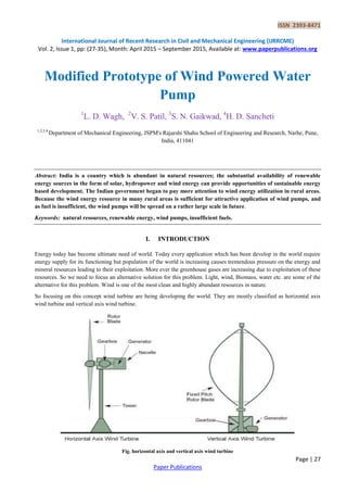
So focusing on this concept wind turbine are being developing the world. They are mostly classified as horizontal axis
wind turbine and vertical axis wind turbine.
Fig. horizontal axis and vertical axis wind turbine
2. ISSN 2393-8471
International Journal of Recent Research in Civil and Mechanical Engineering (IJRRCME)
Vol. 2, Issue 1, pp: (27-35), Month: April 2015 – September 2015, Available at: www.paperpublications.org
Page | 28
Paper Publications
In horizontal axis wind turbine blades are perpendicular to the horizontal axis of rotation. Both rotor shaft and blades are
mounted in the horizontal axis wind turbine require Yaw control mechanism which is used to direct the direction of
rotation of blade in the direction of wind pump. This wind turbines are mostly used for high commercial purpose as
compare to vertical axis wind turbine. This wind turbine are mostly available in the segment of 350kw, 650kw, 1Mw,
2Mw as so on for commercial purpose.
Vertical axis wind turbine are as important as horizontal axis wind turbine from commercial point of view. Vertical axis
wind turbine are developed in world and they have the advantage over horizontal axis wind turbine with absence of Yaw
control system. Due to absence of Yaw control system it acts as Omni direction (it accept wind from all direction).
VAWT need not to be directed in the direction of wind flow. It can be rotated in any condition with different variable
wind flow, here the Darrius wind turbine is discussed below.
With the spinning of Darrius wind turbine, the rotor blades of turbine also move in circular path in forward direction
creating positive angle of attack. Resultant force act on the line of action. The rotor rotate as force is projected inward past
the turbine axis leaving the positive torque to the shaft. The angle of attack changes as per the direction of wind flow. The
rotor spin regardless of wind speed. Thus energy is obtained from the torque and speed due to the rotation of rotor shaft.
More ever the concept of lift and drag is totally neglected in VAWT.
Rigging angle-
It is angle between rotor blades and adjoin structure.
Yaw control system-
It is system used in horizontal axis wind turbine to direct direction of turbine blade in direction of wind flow.
Rotor blade-
Rotor blade used in VAWT robust in construction connected from top to bottom in adjoining assembly. This turbine blade
is symmetric in nature to create positive angle of attack in direction of wind flow.
Electric generator-
Mechanical work is obtained from rotation of turbine blade due to high speed wind and further converted to the torque
leading to generation of electricity.
Fig: Wind operated water pump
3. ISSN 2393-8471
International Journal of Recent Research in Civil and Mechanical Engineering (IJRRCME)
Vol. 2, Issue 1, pp: (27-35), Month: April 2015 – September 2015, Available at: www.paperpublications.org
Page | 29
Paper Publications
Moreover wind mill could also be used for irrigation purpose along with generation of electric power, so the concept of
horizontal wind powered water pump developed in the world. Rotor blades rotate in the direction of wind flow and
motion is transmitted to the pump via gears drives mechanism and connecting rod. The upward and downward movement
of piston takes place in the water pumping. With the upward movement of piston vacuum is created leading to the suction
of water from the source. Thus water is pumped out and the real motto of this technology to obtain the electric power and
pumping of water is obtained.
II. MATERIAL SELECTION
Material selection plays very important role for design and fabrication of any prototype. Material selected should have
optimum and reliable properties as per requirement of variable environmental condition. Commercially many material
with high strength and rigidity are available in the market.
COMMONLY USED MATERIAL IN WIND TURBINE BLADE:
From the past time wood was primarily used for making wind turbine blade. Wood has high rigidity but is possess low
stiffness, so it has limitation of bending. Due to this region it lost its potential for manufacturing of wind turbine blade
with advancement of technology related to wind turbine. With the further research alloy steel was preferred for
manufacturing wind turbine blades, but it is excessive weight brought various problem for turbine assembly. Moreover it
has low fatigue resistance and high cost another material which proved to be useful for manufacturing wind turbine blade
was polymer matrix composite and is used still today. Composite are proving good material for manufacturing the turbine
blades but they are suffering in mechanical properties due to limitation of resin transfer.
FEW MATERIALS USED IN WIND TURBINE BLADES DUE TO THEIR SPECIFIC CHARACTERISTICS:
POLYESTER RESIN-
Polyester Resin is most commonly used material in industry. This material is most preferred for manufacturing turbine
blade as it shows better water resistance ability, its mechanical properties could be improved with the help of suitable
catalyst accelerator and additives. Polyester is chemically resistant but sometimes become brittle where certain shock load
is applied. When turbine blade reaches to certain level while rotation well before its ultimate strength cracks start to
appear. Thus it is poor to handle high fatigue stresses, due to these small cracks water, moisture is well able to penetrate
or adsorbed in the material decreasing its mechanical strength.
EPOXY RESIN-
Epoxy resin is another most wide and suitable material for manufacturing turbine blades. It possess superior properties in
terms of load carrying ability, resistance to environment degradation highly adhesiveness, and tensile strength of 85Mpa
and Young’s modulus of 10.5Gpa. It causes low viscosity and low shrinkage capacity thus maintaining good dimensional
tolerances.
VINYL EASTER RESIN-
This resin had good chemical structure due to which it shows improved shock loading capacity. It has high stiffness,
rigidity, water and chemical resistance, inspired operate good physical and mechanical properties. It is less popular as
found to be having adverse effect of human health.
THERMOPLASTIC-
Matrix here is having good fatigue strength abrasion but, it has problem of disposal techniques which include in land fill,
recycling, incineration etc.
ARAMID FIBRE-
It is also material which possess the properties suitable for manufacturing of turbine blade. It has a high specific strength
and available in the bright golden filament.In spite of its such accident properties t is susceptible to water in grace, ultra
violet ray erosion, sand erosion, insect collision due to this limitation its impact in manufacturing of wind turbine blades
is decreases.
4. ISSN 2393-8471
International Journal of Recent Research in Civil and Mechanical Engineering (IJRRCME)
Vol. 2, Issue 1, pp: (27-35), Month: April 2015 – September 2015, Available at: www.paperpublications.org
Page | 30
Paper Publications
CARBON FIBRE-
It is one of the material which has proved to be most suitable material from the manufacturing point of view in every
application in the developed world. Carbon fibre available in three different categories high strength, intermediate
module, ultra-high module. It has highest strength in tension and compression can possess very high resistance to fatigue,
creep and corrosion. In spite of this most suitable optimum and reliable properties it proves to be less feasible due to its
high cost.
HIGH SUITABILITY OF POLYPROPYLENE MATERIAL-
We discussed many material for manufacturing of our prototype but it has some limitations; so to overcome this
limitations with the material of high mechanical, physical, chemical properties we selected property material.
PP Plastic material has high chemical and corrosion resistance that it has inert nature with less reactivity towards
corrosive chemicals. It is light in weight with high rigidity to overcome sudden high shock loading. It has high tensile
strength so that it can overcome sudden fatigue stresses and avoid forming of cracks and pores. It has excellent abrasion
resistance properties which prove to be helpful for working of wind turbine in adverse environmental conditions with high
wind speeds. It has low moisture absorption properties as cracks and pores are avoided due to high ultimate tensile
strength. It is easy to use and cut due to which it can be fabricated in any required shape. It has excellent thermal
insulation and dielectric properties due to which our prototype can be protected against sudden lighting taking place
moreover it has flame retardant property thus proves to be lifelong material, hence due to all this excellent properties it
proves to be the most optimum material for turbine blade.
III. PERFORMANCE PARAMETER
POWER AVAILABLE IN WIND-
P =
Where,
P = Power available in wind
= Air density in kg/m
r = Radius of blade in m
A = Cross sectional area of blade in m2
TORQUE-
T = =
Where,
T = Torque of shaft in Nm
P = Power available in wind in Watts
= Angular velocity in rad/sec
TIP SPEED RATIO-
=
Where,
= Tip speed ratio
n = Number of blade
5. ISSN 2393-8471
International Journal of Recent Research in Civil and Mechanical Engineering (IJRRCME)
Vol. 2, Issue 1, pp: (27-35), Month: April 2015 – September 2015, Available at: www.paperpublications.org
Page | 31
Paper Publications
FORCE ON BLADE-
F =
Where,
F = Force act on blade in N
= Air density in kg/m
= Swept area in m2
= Air velocity in m/s
DRAG FORCE ACTING ON BLADE-
FD =
FD = Drag force acting on blade
= Air density in kg/m
= Swept area in m2
= Air velocity m/s
Cd = Drag force coefficient
LIFT FORCE ACTING ON BLADE-
FL =
Where,
FL = Lift force acting on blade in N
= Air density in kg/m
= Swept area in m2
= Air velocity m/s
EFFICIENCY-
=
= Efficiency
Pt = Power in turbine in Watts
Pw = Power in wind in Watts
IV. COMPONENTS OF WORKING HORIZONTAL WIND OPERATED WATER PUMP
BLADE:
Blades are most important components in turbine assembly as it capture wind. Blade positioning and orientation plays a
very important role as it decides the intensity of air captured by the turbine blade. So looking for this point of view to
optimize our turbine efficiency we experimented two different types of blade.
First blade we used is cup in shape of PVC plastic material for manufacturing of our turbine blades. Intensity of wind
captured increased as turbine blade poses the cup shaped which proved to be helpful for generation of required
mechanical work leading to generation of electric power and water pump. But it has a limitation of being comparatively
light, as per the size and shape of prototype to be handled under different variable condition with different wind speed.
6. ISSN 2393-8471
International Journal of Recent Research in Civil and Mechanical Engineering (IJRRCME)
Vol. 2, Issue 1, pp: (27-35), Month: April 2015 – September 2015, Available at: www.paperpublications.org
Page | 32
Paper Publications
So to overcome this limitation and use suitable and optimum material for turbine blade according to prototype design
requirement we found Polypropylene plastic material.
Fig. Polypropylene plastic material blade
Polypropylene plastic material is light in weight but possess high strength and rigidity as compared to PVC plastic
material. Moreover it can be easily fabricated to the aerodynamic shape as per the requirement of prototype. Due to
aerodynamic shape been provided with help of PP material, efficiency of the overall system improves according to Betz
limit.
CRANKSHAFT:
Fig. Crank Shaft
Another most important component for the smooth functioning of prototype is crankshaft. Crankshaft should poses high
strength, rigidity and toughness due to these requirement they are manufactured by casting and forging production
techniques. Crankshaft is component connected between the turbine blade and connecting rod. With the rotation of
turbine blade, certain mechanical motion is obtained which is transmitted to the crankshaft leading to rotary motion of
connecting rod with piston in the pumping assembly.
CONNECTING ROD:
Fig: Connecting rod
7. ISSN 2393-8471
International Journal of Recent Research in Civil and Mechanical Engineering (IJRRCME)
Vol. 2, Issue 1, pp: (27-35), Month: April 2015 – September 2015, Available at: www.paperpublications.org
Page | 33
Paper Publications
Connecting rod is long slender component between crankshaft and piston assembly via sew-saw mechanism. Mechanical
motion obtained from the crankshaft for the reciprocation of piston rod in pumping assembly is transmitted via connecting
rod. Connecting rod should have high ultimate tensile stress, resistance for the bending, fatigue stresses so it should be
manufactured by casting and forging production techniques.
SEW-SAW MECHANISM:
Fig. Sew-saw mechanism
Sew-saw mechanism is the basic principle for reciprocation of piston in pumping assembly is achieved by sew-saw
mechanism. Blade rotate further leading to the rotatory motion of crankshaft. This rotatory motion is further transmitted
in the form of transverse motion for the reciprocation of piston rod in pumping assembly.
PUMPING ASSEMBLY
Pumping assembly is the most important sub system of prototype as it carry out work of pumping of water here in the
pumping assembly we use a single acting reciprocating piston. Due to sew-saw mechanism piston moves upward and
downward in pumping assembly with the upward movement of piston in pumping assembly vacuum is created in pump.
Due to this vacuum suction of water takes place for the commercial use from the required given outlet.
ALTERNATOR:
From the developed prototype, alternator plays an important role from the electric power generation point of view.
Alternator is provided on the back side of prototype. Alternator is connected to the connecting rod via small shaft. With
the rotatory motion of the crankshaft, mechanical motion is transmitted to the alternator by the small shaft through its
rotation. Due to rotation of the alternator shaft, electromagnetic flux is generated in the alternator assembly leading to the
development electromotive force which produce electric power.
WORKING ASSEMBLY:
Fig: Assembly of wind powered water pumping
Horizontal wind powered water pump proves to be hybrid system for generations of electricity and pumping of water for
the commercial purposes.
8. ISSN 2393-8471
International Journal of Recent Research in Civil and Mechanical Engineering (IJRRCME)
Vol. 2, Issue 1, pp: (27-35), Month: April 2015 – September 2015, Available at: www.paperpublications.org
Page | 34
Paper Publications
Polypropylene plastic blades rotate with the intensity of wind bombarded on it. Due to rotation of turbine blades
mechanical motion is transmitted to the crankshaft leading to its rotatory motion. This rotatory motion of crankshaft is
further transmitted to the piston of pumping assembly via sew-saw mechanism and connecting rod. The motion of piston
is between the top of dead centre and bottom of pumping assembly. When the piston is at the top dead centre, vacuum is
created in pumping assembly. This leads to suction of water for required commercial purpose. Moreover from the
electricity generation point of view alternate shaft is connected to the crankshaft. With the rotatory motion of crankshaft,
electromagnetic flux is produced in alternator leading to generation of electric power.
V. RESULTS
Table. Result table of aerodynamic shape of blade
Sr. No. Wind Velocity (m/s) Water Discharge (ml) Head (m)
1 2.89 400 0.8
2 3.82 485 1.0
3 4.49 530 1.5
4 4.97 600 1.8
5 5.36 670 2.5
6 5.79 720 3.0
7 6.5 760 3.4
Table. Result table of cup shape of blade
Sr. No. Wind Velocity (m/s) Water Discharge (ml) Head (m)
1 2.89 350 0.5
2 3.82 400 0.7
3 4.49 440 1.0
4 4.97 560 1.5
5 5.36 620 1.8
6 5.79 670 2.3
7 6.5 720 2.5
0
100
200
300
400
500
600
700
800
0 1 2 3 4 5 6 7
Discharge(ml)
WIND VELOCITY(m/s)
GRAPH-1-WIND VELOCITY Vs DISCHARGE
cup shape of blade Aerodynamic Shape
9. ISSN 2393-8471
International Journal of Recent Research in Civil and Mechanical Engineering (IJRRCME)
Vol. 2, Issue 1, pp: (27-35), Month: April 2015 – September 2015, Available at: www.paperpublications.org
Page | 35
Paper Publications
VI. CONCLUSION
From the prototype design, it can be concluded that, the total torque of the windmill is 3.27 N-m and this is sufficient to
sustain the desired flow rate of 2.35 lit/min with a maximum head of 1.5 m at 45 rpm and also to overcome other
barriers to motion.
The numbers of blades used is 3 with a total surface area of 1.8381 m2
and this gives a solidity of 0.8, the minimum
value of solidity for a windmill and therefore ensures conformity with the standard specifications.
ACKNOWLEDGMENT
The authors would like to present their sincere gratitude towards the faculty of Department of Mechanical Engineering,
JSPM's Rajarshi Shahu School of Engineering and Research, Narhe, Pune, 411041.
REFERENCES
[1] "Mechanical Engineering in the Medieval Near East", Donald Routledge Hill, Scientific American, May 1991.
[2] “Wind Energy Comes of Age”, Paul Gipe& John Wiley and Sons, ISBN 0-471-10924-X, 1995.
[3] “The Mechanical Design, Analysis, and Testing of a Two-Bladed Wind Turbine Hub”, J. Cotrell, National
Renewable Energy Laboratory is a U.S. Department of Energy Laboratory Operated by Midwest Research Institute,
June 2002.
[4] “The material selection for typical wind turbine blades using a approach& analysis of blades”, K.SureshBabu,
N.V.SubbaRaju, M.Srinivasa Reddy, Dr. D. NageswaraRao, MCDM 2006, Chania, Greece, June 19-23, 2006.
[5] “General Assessment of Fiber-Reinforced Composites Selection in Wind Turbine Blades”, AysegulAkdoganEker,
BulentEker, the World Academic Publishing Co. Ltd, 20, December 2013.
[6] “Wind Blade Material Optimization”, Samir Ahmad &Dr.Izhar-ul-Haq, Advances in Mechanical Engineering,
ISSN:2160-0619, Volume 2, Number 4, December, 2012.
[7] “Wind Turbine Blade Design”, Peter J. Schubel and Richard J. Crossley, Faculty of Engineering, Division of
Materials, Mechanics and Structures, University of Nottingham, University Park, Nottingham, Energies 2012.
0
0.5
1
1.5
2
2.5
3
3.5
4
0 1 2 3 4 5 6 7
HEAD(M)
WIND VELOCITY(m/s)
GRAPH 2-WIND VELOCITY Vs HEAD
Aerodynamic Shape cup shape of blade