Lss6330 catalogue noiseken_Lightning_surge_simulator_denkei
•
0 likes•25 views

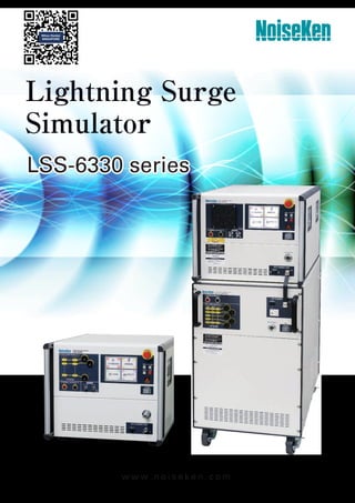
A tester simulatively generates "High energy induced lightning noise" which induced to distribution lines or communication lines by ground potential fluctuation caused by lightning strikes. Conforming to IEC 61000-4-5 Ed.3, IEC61000-4-12 Ed.3(RINGWAVE 100kHz)and ANSI IEEE62-45(2002) *

Recommended
More Related Content
What's hot
What's hot (20)
Similar to Lss6330 catalogue noiseken_Lightning_surge_simulator_denkei
Similar to Lss6330 catalogue noiseken_Lightning_surge_simulator_denkei (20)
More from NIHON DENKEI SINGAPORE
More from NIHON DENKEI SINGAPORE (20)
Recently uploaded
Recently uploaded (20)
Lss6330 catalogue noiseken_Lightning_surge_simulator_denkei
- 1. Lightning Surge Simulator LSS-6330 series LSS-6330 series w w w . n o i s e k e n . c o m
- 2. 2 w w w. n o i s e k e n . c o m ch2 ch1 Oscilloscope Coaxial cable EUT LINE OUTPUT 240V/20A MAX ~ 125V/20A MAX L + N - PE PE AC DC SURGE OUTPUT HOT COM MONITOR V(1/1000) I(1/1000) A20 Lightning Surge Simulator LSS-6330 CDN IF FG EXT CONNECTION Monitor connection Lightning Surge Simulator LSS-6330 SURGE OUTPUT HOT COM MONITOR V(1/1000) I(1/1000) S EUT LINE OUTPUT 600V/63A MAX ~ 125V/63A MAX L1 + L2 - L3 N PE PE 3PHASE AC 1PHASE AC DC N L PE HOT COM SURGE INPUT Lightning Surge Simulator LSS-6330 CDN IF FG EXT CONNECTION ON OFF LINK EUT LINE OUTPUT 240V/20A MAX ~ 125V/20A MAX L + N - PE PE AC DC SURGE OUTPUT HOT COM MONITOR V(1/1000) I(1/1000) A20 Lightning Surge Simulator LSS-6330 CDN IF FG EXT CONNECTION Energizing state ON/OFF selection Interlock terminal Emergency stop WARNING Lamp Safety socket Lightning Surge Simulator LSS-6330 series A tester simulatively generates "High energy induced lightning noise" which induced to distribution lines or communication lines by ground potential fluctuation caused by lightning strikes. ● Conforming to IEC 61000-4-5 Ed.3, IEC61000-4-12 Ed.3 (RINGWAVE 100kHz) and ANSI IEEE62-45(2002)* ● Surge voltage up to 6.7 kV. ● CDN: Single phase up to 20A, AC240V/DC125V. Three phase up to 63A, AC600V/DC125V. ● Pre-checking function simplifies start-up inspection works. ● Voltage and current monitors enable status monitoring during noise applied to EUT. ● Large LCD operation panel improves visibility and operability. ● Easy out put current & voltage report. ● Interlocking function provides excellent safety. ● MPU control function simplifies continuous testing, enables automatic surge-out, waveform-switching and polarity switching. ● Equipped with both manual and program mode to simplify test condition setting. Manual mode: for standard and single-shot testing. Program mode: for different testing in succession. ● Equipped withwaveform checking terminals provide easy output waveform checking with existing oscilloscope and BNC cables. ● Isolation transformer available for safety protection for superimposing circuit current leakage and back surge to power source.(Option) Pre-checking function simplifies start-up inspection works <Conventional>: It requires for two expensive high voltage probes and differential measurement available oscilloscope for start-up inspection works. <LSS-6330>: Simplifies start-up inspection works only by connecting dedicated cables to the tester to confirm whether or not the output is present. (pre-checking). (Available for SURGE OUTPUT/EUT LINE OUTPUT) Incorporated“Emergency stop” and“Interlock function” to improve operation safety. Equipped with operation safety functions in both hardware and software. Safety sockets as well as emergency stop switches and interlock terminals secure operation safety when connecting EUT. In addition, further safety is available by using“protection fences”and “protection boxes”. (option) Waveform checking terminal enables output waveform monitoring We received many market feedbacks say“I want to check the output waveform during the test”, the answer is“Yes we can”. We incorporated the checking terminal, and it enables monitoring of applied waveforms to EUT via oscilloscopes during tests. Furthermore, even without oscilloscopes, you could check the voltage & current value on the upgraded monitor screen as well. Visualize the testing connection status on monitor display for easy testing condition understanding Monitor screen displays connection status in order to avoid incorrect power line connection. In addition, an outlet box (option) simplifies testing connection. *For Ring Wave coupling, simultaneous application is possible only for the Basic test type with PE as surge COM. model specification LSS-6330-A20 left picture : single phase 20A type lightning surge simulator LSS-6330-B63 right picture : three phases 63A type lightning surge simulator
- 3. L I G H T N I N G S U R G E S I M U L A T O R 3 w w w. n o i s e k e n . c o m 日本語 英語 中国語 韓国語 ■ Surge generator unit LSS-6330-A20 / -B63 both applicable Item/Parameter Specification Note Surge Waveform 1.2/50μs-8/20μs combination 10/700μs-5/320μs combination RING WAVE 1.2/50μs-8/20μs combination Open voltage 0.5kV ∼ 6.7kV ±10% Coupling circuit:18μF Cable length:One side 0.5m Line input side open Front time 1.2μs±30% Time to half-value 50μs±20% Short-circuited current 250A ∼ 3350A ±10% Front time 8μs ±20% Time to half-value 20μs ±20% 10/700 μs-5/320μs combination Open voltage 0.5kV ∼ 6.7kV ±10% Cable length:One side 0.5m Front time 10μs ±30% Time to half-value 700μs ±20% Short-circuited current 12.5A ∼ 167.5A ±10% Front time 5μs ±20% Time to half-value 320μs ±20% RING WAVE Open voltage 0.25kV ∼ 6.6kV ±10% Cable length:One side 0.5m Front time 0.5μs ±30% Frequency 100kHz ±10% Waveform envelop Pk2 = 40% < Pk1 < 110% Pk3 = 40% < Pk2 < 80% Pk4 = 40% < Pk3 < 80% Short-circuited current 8.3 ∼ 550A ±10% Front time 0.2 ∼ 1μs Palarity +/- Output impedance 2Ω ±10% 1.2/50μs waveform 40Ω ±10% 10/700μs waveform 12Ω ±20%、30Ω ±20% RING (selectable) PC control software simplifies overall test processes It is so easy to set complicate test sequences of various test types, save test results & records and generate test reports. Multilingual localization provides easy test condition setting Multilingual touch panel display supports easy and sure test setting. Languages in English, Chinese, Korean and Japanese. LSS-6330 series Specification
- 4. 4 w w w. n o i s e k e n . c o m Item/Parameter Specification Note Surge generation circuit Floating Minimum charging time 0.0kV ∼ 4.0kV:5 sec 4.1kV ∼ 6.7kV:10 sec 1.2/50μs波形 0.0kV ∼ 4.0kV:10 sec 4.1kV ∼ 6.7kV:15 sec 10/700μs 波形 0.0kV ∼ 6.6kV:1 sec RING WAVE Communication fuction RS-232C (Optical connector), Bluetooth Option External CDN control Emergency stop Push-lock(Test STOP, High voltage OFF, EUT switch SHUT OFF) Interlock function External connection status detection Emergency lamp Red LED blinking after start the tests Emergency lamp connector Equiped with emergency lamp connectors. Lamp blinking after start the tests. 3ports EUT Fail 3ports Voltage monitor BNC output、2000V/V ±10% Accuracy:±10% vs. actual output When output is open, no waveform prescription Current monitor BNC output、1000A/V ±10% Accuracy:±10% vs. actual output When output is short-circuited, no waveform prescription Phase angle control 0°∼360°±10° EUT power AC90V Min. 50Hz/60Hz ±10% Trigger input asychronous , synchronized to AC line 0°~360° / 1° step, external input Power supply AC100V ∼ AC240V ±10% 50Hz / 60Hz ±10% Operational environment Humidity:15 ∼ 35℃ Temperature:25 ∼ 75%RH Dimentions / weight (W)430 × (H)371 × (D)530 mm / approx 55kgs ■ AC / DC Line Injection Part LSS-6330-A20 Item/Parameter Specification Note Surge Waveform 1.2/50μs-8/20μs combination、RING WAVE 1.2/50μs-8/20μs combination Open voltage 0.5kV ∼ 6.7kV ±10% Coupling circuit:18μF Cable length:One side 0.5m Line input side open Front time 1.2μs ±30% Time to half-value 50μs ±20% Short-circuited current 250A ∼ 3350A ±10% Front time 8μs ±20% Time to half-value 20μs ±20% Open voltage 0.5kV ∼ 6.7kV ±10% Coupling circuit::10Ω+9μF Cable length:One side 0.5m Line input side open Front time 1.2μs ±30% Time to half-value 50μs +10μs /-25μs Short-circuited current 41.6A ∼ 558A ±10% Front time 2.5μs ±30% Time to half-value 25μs ±30% RING WAVE Open voltage 0.25kV ∼ 6.6kV ±10% Coupling circuit::4.5μF Cable length:One side 0.5m Line input side open Front time 0.5μs ±30% Frequency 100kHz ±10% Waveform envelop Pk2 = 40% < Pk1 < 110% Pk3 = 40% < Pk2 < 80% Pk4 = 40% < Pk3 < 80% Short-circuited current 8.3 ∼ 550A±10% Front time 0.2 ∼ 1μs Power Capacity for EUT line AC240V/20A MAX 50/60Hz、DC125V/20A MAX Decoupling coil 1.5mH Voltage dip Less than 10% of the rated voltage when the rated current is energized Trough AC line injection part terminal Residual voltage Less than 15% of the injected voltage or less than double of the rated voltage (peak value) LSS-6330 series
- 5. L I G H T N I N G S U R G E S I M U L A T O R 5 w w w. n o i s e k e n . c o m ■ AC / DC Line Injection Part LSS-6330-B63 Item/Parameter Specification Note Surge Waveform 1.2/50μs-8/20μs combination、RING WAVE 1.2/50μs-8/20μs combination Open voltage 0.5kV ∼ 6.7kV ±10% Coupling circuit:18μF Cable length:One side 0.5m Line input side open Front time 1.2μs ±30% Time to half-value 50μs ±20% Short-circuited current 250A ∼ 3350A ±10% Front time 8μs ±20% Time to half-value 20μs ±20% Open voltage 0.5kV ∼ 6.7kV ±10% Coupling circuit::10Ω+9μF Cable length:One side 0.5m Line input side open Front time 1.2μs ±30% Time to half-value 50μs +10μs /-25μs Short-circuited current 41.6A ∼ 558A ±10% Front time 2.5μs ±30% Time to half-value 25μs ±30% RING WAVE Open voltage 0.25kV ∼ 6.6kV ±10% Coupling circuit::4.5μF Cable length:One side 0.5m Line input side open Front time 0.5μs ±30% Frequency 100kHz ±10% Waveform envelop Pk2 = 40% < Pk1 < 110% Pk3 = 40% < Pk2 < 80% Pk4 = 40% < Pk3 < 80% Short-circuited current 8.3 ∼ 550A±10% Front time 0.2 ∼ 1μs Power Capacity for EUT line AC690V/63A MAX 50/60Hz、DC125V/63A MAX Decoupling coil 1.5mH Voltage dip Less than 10% of the rated voltage when the rated current is energized At the output terminal of the AC superposition section Residual voltage Less than 15% of the injected voltage or less than double of the rated voltage (peak value) Phase angle control 0°~360°±10°Operates at EUT power supply AC90V min. & 50Hz / 60Hz ± 10% Power supply AC100V ∼ AC240V ±10% 50Hz / 60Hz ±10% Operational environment Humidity:15 ∼ 35℃ Temperature:25 ∼ 75%RH Dimentions (W)430 × (H)695 × (D)686 mm ■ Standard accessries (LSS-6330-A20) Items Quantity Note AC cable 1 pc PE cable 1 pc round solderless tip - round solderless terminal Surge output cable(HOT ・COM) 1 pc each (totally 2 pcs) multi-contact: plug - round solderless terminal Waveform verification cable (Surge output) 1 pc multi-contact: plug - multi-contact: plug (for pre-check) Waveform verification cable (CDN output) 1 pc multi-contact: plug - multi-contact: plug (for pre-check) Line input cable (05-00162A) 3 pcs multi-contact: plug - bar solderless terminal、 Single wire Line outupt cable 3 pcs multi-contact: plug - round solderless terminal Interlock connector 1 pc BNC cable for monitor 1 pc Accessory bag 1 pc Instruction manual 1 volume ■ Standard accessries (LSS-6330-B63) Items Quantity Note AC cable 1 pc PE cable 1 pc round solderless tip - round solderless terminal Surge output cable(HOT ・COM) 1 pc each (totally 2 pcs) multi-contact: plug - round solderless terminal Waveform verification cable (Surge output) 1 pc multi-contact: plug - multi-contact: plug (for pre-check) Waveform verification cable (CDN output) 1 pc multi-contact: plug - multi-contact: plug (for pre-check) Line input cable(05-00163A) 5 pcs multi-contact: plug - bar solderless terminal、 Single wire Line outupt cable 5 pcs multi-contact: plug - round solderless terminal CDN connection cable(HOT・COM) 1 pc each (totally 2 pcs) Connection cable between CDN and PE on main unit 1 pc CDN control cable 1 pc Interlock connector 1 pc BNC cable for monitor 1 pc Accessory bag 1 pc Instruction manual 1 volume LSS-6330 series
- 6. 6 w w w. n o i s e k e n . c o m FNSront panel EUT LINE OUTPUT 240V/20A MAX ~ 125V/20A MAX L + N - PE PE AC DC SURGE OUTPUT HOT COM MONITOR V(1/1000) I(1/1000) A20 Lightning Surge Simulator LSS-6330 CDN IF FG EXT CONNECTION Lightning Surge Simulator LSS-6330 SURGE OUTPUT HOT COM MONITOR V(1/1000) I(1/1000) EUT LINE OUTPUT 600V/63A MAX ~ 125V/63A MAX L1 + L2 - L3 N PE PE 3PHASE AC 1PHASE AC DC N L PE HOT COM SURGE INPUT Lightning Surge Simulator LSS-6330 CDN IF FG EXT CONNECTION ON OFF LINK Lightning Surge Simulator LSS-6330 SURGE OUTPUT HOT COM MONITOR V(1/1000) I(1/1000) EUT LINE OUTPUT 600V/63A MAX ~ 125V/63A MAX L1 + L2 - L3 N PE PE 3PHASE AC 1PHASE AC DC N L PE HOT COM SURGE INPUT Lightning Surge Simulator LSS-6330 CDN IF FG EXT CONNECTION ON OFF LINK SURGE IN / EUT LINE OUTの拡大 LSS-6330 series
- 7. L I G H T N I N G S U R G E S I M U L A T O R 7 w w w. n o i s e k e n . c o m Telecom interconnection simulator Surge generator output port Isolation transformer Wooden table PE cable Surge simulator EUT EUT Power supply High-speed communication lines CDN Item Specificaion / Performance Surge Input Volatage 6.6kV EUT Power Supply Capacity DC50V 100mA Max. Line Number 4 Lines Decoupling Coil 20mH each line Matching Resistor 40Ω (1.2/50μs-8/20μs Combination wave) 25Ω (10/700μs-5/320μs Combination wave) Dimensions / Weight (W)297×(H)262×(D)250mm Approx.10kgs * The product in the photo is under development. EUT Surge generator output port Isolation transformer Wooden table PE cable Surge simulator Telecom line CDN Telecom interconnection simulator Telecom interconnection simulator EUT Power supply EUT AE Surge generator output port Wooden table PE cable Surge simulator EUT Power supply Unshielded unsymmetrical interconnection lines CDN Interconnection cable between the EUT and AE (e.g.RS232C) Isolation transformer Parameter F-130814-1004-2 F-130814-1004-4 Maximum input voltage 2kV 4kV EUT power capacity DC65V/1A Maximum line Number 8 lines EUT/AE connector RJ-45 Dimensions (W)400×(H)230×(D)240mm High-speed communication lines CDN for LSS-F03 series Defined in the IEC 61000-4-5 , this CDN product is used to apply surg- es to unshielded symmetrical interconnection lines with speed up to 1000Mbit/s. Conversion cables (05-00164A) are required for the CDN connection to the LSS-6330 simulator. Used for the surge test to interconnection lines defined in IEC61000-4-5 Standard. The EUT power capacity is DC50V/1A and enable to inject the surge to interconnection lines up to 6,600V. Possible to bypass inductor (20mH) with connecting the attached connection plug to in- ductor bypass terminal in DC output. Possible to equip the attached surge protective arrestor between each line and ground. * The conversion (05-00165)cable is needed additionally. Defined in IEC61000-4-5 , this CDN product is used to apply surges to interconnection lines for unshielded subject or telecom lines. *Please inquire to us for details. Parameter Specification Surge input voltage 500V~6.600V (Combination wave) EUT power capacity DC50V / 1A Max. line number 4 lines Decoupling coil 20mH each line Matching resistor 40Ω±10% Dimensions / Weight (W) 488x(H)456x (D) 550mm Approx. 45kgs CDN for Interconnection Lines for LSS-F03 series MODEL : LSS-INJ6401SIG Telecom line CDN Option
- 8. 8 w w w. n o i s e k e n . c o m Protective Safety Fence MODEL : 11-00010A Tri-color pilot light MODEL: 11-00015A Optical USB module MODEL:07-00022A Terminal block board for CDN to connect EUT. 3 pins *Conversion cable (model: 05-00166A) is required. Terminal block board for CDN to connect EUT. 5 pins *Conversion cable (model: 05-00167A) is required. OUTLET BOX 18-00081A Outlet box 125V 15A 2P+PE Btype (3Ptype、 JP/USAtype) AC125V 15A MAX 18-00082A multi-outlet box Japan(JIS), America(UL), Canada(CSA), Australia(CSA), Swiss(SEV), Italy(CEI), Europe(CEE, DIN), England(BS) Input up to 4.5kV 18-00083A Outlet box Europe CEE DIN 250V 16A MAX 18-T2300 3P Terminal Block Conversion Box 3P terminal block M6 with protective cover Input up to 5kV *This product is a custom product. Please contact us for details. 18-N2494 5P Terminal Block Conversion Box 5P terminal block M6 with protective cover Input up to 5kV *This product is a custom product. Please contact us for details. Alarm lamp for LSS series. Alarm lamp illuminated when high voltage is generated at the time of test This product is an outlet box for converting a line output socket to a terminal block type. Conversion adapter to interface with PC for the remote control of LSS USB to optical interface. Fiber cable 5m included. Protection box to prevent access to EUT during the test. Further safety is secured together with the safety pro- tective fence EUT Protective Safety Box MODEL : 11-00005A/11-00006A MODEL Dimension 11-00005A W400×D300×H300mm 11-00006A W600×D400×H350mm Terminal connection board for the output of LSS-6230-A20 to connect EUT. By wiring with multi-outlet, plug compliant to each country's standard can be inserted directly. single phase 3 lines (withstand vlotage 4.5kV) *Conversion cable (model: 05-00166A) is re- quired. Terminal Connection Board attached with Multi-Outlet(3P) MODEL : 18-00048B Terminal connection board for the output of LSS-6230-A20 to connect EUT. By wiring with multi-outlet, plug compliant to each country's standard can be inserted directly. three phases 5 lines (withstand vlotage 4.5kV) *Multi-outlet is for single phase. Terminal Connection Board attached with Multi-Outlet(3P) MODEL : 18-00058B Enable to materialize the safe test environment with connection to inter- lock function equipped in LSS-F03 series. The safety measure can be sure together with the EUT protective safety box. Usable together with LSS-5330-A20. The blinking makes the operators or neighbors pay attention to the test pro- cessig. Three colors indicate corresponing simulator's test status change. Warning Lamp MODEL: 11-00008A Terminal Block for 3P MODEL: 18-00047A Terminal Block for 5P MODEL: 18-00044A Option
- 9. L I G H T N I N G S U R G E S I M U L A T O R 9 w w w. n o i s e k e n . c o m MODEL Primary Voltage / Secondary Voltage Rated current Frequency NCT-160 120V 5A 50/60Hz NCT-1120 10A NCT-1240 20A NCT-260 240V 2.5A NCT-2120 5A NCT-2240 10A Item Specification (18-00072A) Specification (18-00073A) Rated Voltage AC250V 50/60Hz DC65V AC240/415V, 3 phase 4 wire Y-connection, 50/60Hz Line-N (neutral): AC240V Line-Line: AC415V Rated Current 20A 50A Endurance 10,000 times or more open/close Neutral pole(N pole) (Rated open/close 6,000 times, No trip alone Neither open-circuit before pther poles nor closed-circuit after the other poles Operating Temperature / Operating Humidity No load open/close 4,000 times, Dimensions 6 times / minutes) (W)180×(H)92×(D)120mm (projection excluded) Weight 0.75 kg 1.2kg Isolation Transformer MODEL : TF-2302P Isolation Transformer MODEL : TF-6503P, TF-6633P Circuit Breaker Box MODEL : 18-00072A/73A Noise Canceller Transformer NCT series Model TF-2302P is a single-phase isolation transformer rated AC240V/30A and dielectric strength of 4kV. For safety reason, an isolation transformer is indispensable for AC powered testing for equipment. Parameter Specification Maximum input voltage Single phase AC240V Max (50/60Hz) Maximum output current 30A Max Dielectric strength Primary winding to core AC4kV (1 minute) Secondary winding to core AC4kV (1 minute) Primary to secondary windings AC4kV (1 minute) Insulation resistance 100MΩ or more at DC500V Dimensions / Weight 350(w) x 475(h) x 400(d)mm (Except for eye bolt and handle) Approx. 60kgs Model TF-6503P is a three-phase isolation transformer rated AC600V/50A(TF-6633P,63A) and dielectric strength of 4kV. For safety reason, an isolation transformer is indispensable for AC powered testing for equipment. Model TF-6503P is a three-phase isolation transformer rated AC600V/50A and dielectric strength of 4kV. For safety reason, an isolation transformer is indispensable for AC powered testing for equipment. It has superb attenuation characteristics against impulse noises. It can be used for insulate in the impulse noise test. *Connection cable is needed to be modified when it is connected with the transformer. Please inquire us for details. Parameter Specification Maximum input voltage Single/Three phase AC600V Max (50/60Hz) Transformer wiring method Star wiring Maximum output current TF-6503P, 50A Max TF-6633P, 63A MAX Dielectric strength Primary winding to core AC 4kV (1 minute) Secondary winding to core AC 4kV (1 minute) Primary to secondary windings AC 4kV (1 minute) Insulation resistance 100MΩ or more at DC500V Dimensions / Weight 500(w) x 640(h) x 700(d)mm (Except eye bolt and handle) Approx. 350kgs Option
- 10. 10 w w w. n o i s e k e n . c o m Tw Tr Isc normalized 0 ~ -0.3 t 1.0 0.9 0.5 0.3 0.1 0.0 Front time: Tf = 1,25 × Tr = 8μs ±20 % Duration: Td = 1,18 × Tw = 20μs ±20 % Tw Voc normalized T 0 ~ -0.3 t 1.0 0.9 0.5 0.3 0.1 0.0 Front time: Tf = 1,67 × T = 1,2μs ±30% Duration: Td = Tw = 50μs ±20% IEC61000-4-5 Ed.3 Test Standard The task of the described laboratory test is to find the reaction of the EUT under specified operational conditions, to surge voltages caused by switching and lightning effects at certain threat levels. This standard specifies 2 kinds of the combination waveforms. One is simulating the injection to power supply lines and interconnections lines (The voltage waveform as 1.2/50μs and current waveform as 8/20μs) and the other is doing the injection to telecommunications lines (The voltage waveform as 10/700μs and current waveform as 5/320μs). It is not intended to test the capability of the EUT’s insulation to withstand high-voltage stress, direct injections of lightning currents, i.e., direct lightning strikes, are not considered in this standard. U High-voltage source Rc Charging resistor Cc Energy storage capacitor Rs Pulse duration shaping resistors Rm Impedance matching resistor Lr Rise time shaping inductor Cc Rc Rm Rs1 Rs2 Lr U ■ Current Surge (8/20μs) ■ Generation Circuit ■ 1.2/50μs Combination Waveform specification ■ 1.2/50μs Voltage waveform specification at the EUT port of the power line CDN (open-circuit voltage) ■ Voltage Surge (1.2/50μs) 1. General 2. Test Level 3. Waveforms Generator and Waveforms verification 4. Voltage waveform specification at the EUT port of power line CDN Level Open-circuit test voltage kV Normal model Common mode 1 - 0.5 2 0.5 1.0 3 1.0 2.0 4 2.0 4.0 x special special x: Can be any level, above, below or in between the others. The level shall be agreed upon between the manufacturers and users. Front time Tf µs Duration Td µs Open-circuit voltage Tf = 1,67 × T = 1,2 ± 30 % Td = Tw = 50 ± 20 % Short-circuit current Tf = 1,25 × Tr = 8 ± 20 % Td = 1,18 × Tw = 20 ± 20 % Open circuit votlage * Coupling impedance 18 µF (line to line) 9 µF + 10 Ω (line to ground) Peak voltage Current rating ≦ 16 A 16 A < current rating ≦ 32 A 32 A < current rating ≦ 63 A 63 A < current rating ≦ 125 A 125 A < current rating ≦ 200 A Set voltage +10 %/-10 % Set voltage +10 %/-10 % Set voltage +10 %/-10 % Set voltage +10 %/-10 % Set voltage +10 %/-10 % Set voltage +10 %/-10 % Set voltage +10 %/-10 % Set voltage +10 %/-15 % Set voltage +10 %/-20 % Set voltage +10 %/-25 % Front time 1,2 µs ± 30 % 1,2 µs ± 30 % Duration Current rating ≦ 16 A 16 A < current rating ≦ 32 A 32 A < current rating ≦ 63 A 63 A < current rating ≦ 125 A 125 A < current rating ≦ 200 A 50 µs + 10 µs/ -10 µs 50 µs + 10 µs/ -15 µs 50 µs + 10 µs/ -20 µs 50 µs + 10 µs/ -25 µs 50 µs + 10 µs/ -30 µs 50 µs + 10 µs/ -25 µs 50 µs + 10 µs/ -30 µs 50 µs + 10 µs/ -35 µs 50 µs + 10 µs/ -40 µs 50 µs + 10 µs/ -45 µs * A CDN meeting the current rating of the EUT and its relevant waveform specification from this table shall be used.
- 11. L I G H T N I N G S U R G E S I M U L A T O R 11 w w w. n o i s e k e n . c o m C=9μF R=10Ω L N PE Decoupling network Coupling network AC/DC power supply network EUT port Combination wave generator S1 1 2 3 4 S2 1 2 3 4 C=18μF L1 L2 L3 N PE EUT port Coupling network Decoupling network AC power supply network Combination wave generator Open-circuit peak voltage +/-10% at EUT port of the CDN Short-circuit peak current +/-10% at EUT port of the CDN (18μF) Short-circuit peak current +/-10% at EUT port of the CDN (9 µF + 10 Ω) 0,5 kV 0,25 kA 41,7 A 1,0 kV 0,5 kA 83,3 A 2,0 kV 1,0 kA 166,7 A 4,0 kV 2,0 kA 333,3 A Decoupling network C=18μF Coupling network AC/DC power supply network EUT port L N PE Combination wave generator EUT port R=10Ω Coupling network Decoupling network C=9μF AC power supply network L1 L2 L3 N PE Combination wave generator S2 1 2 3 4 Surge current parameters under short-circuit conditions Coupling impedance 18 µF (line to line) 9 µF + 10 Ω (line to ground) Front time Tf = 1,25 × Tr = 8µs ± 20 % Tf = 1,25 × Tr = 2,5 µs ± 30 % Duration Td=1.18×Tw=20μs±20% Td = 1,04 × Tw = 25 µs ± 30 % ■ Current waveform specification at the EUT port of the power line CDN (short-circuit current) ■ Single phase power line CDN (line to line mode) ■ Single phase power line CDN (line to ground mode) ■ hree-phase power line CDN (line to ground mode) ■ hree-phase power line CDN (line to line mode) ■ Relationship between peak open-circuit voltage and peak short-circuit current at the EUT port of the power line CDN IEC61000-4-5 Ed.3 Test Standard
- 12. 12 w w w. n o i s e k e n . c o m RD AE EUT L1A L1B L2 L2 L3B L3A C1B C1A C2B RA RB C2A RC Decoupling network Coupling network Combination wave generator Coupling method Output voltage from the generator Voltage at the EUT port of the CDN Voc ±10 % Voltage front time Tf = 1,67 ×Tr ±30 % Voltage duration Td = Tw ±30 % Short-circuit current at the EUT port of the CDN Isc ±20 % Current front time Tf=1,25xTr ±30 % Current Duration Td=1,18xTw ±30 % Line to PE R = 40Ω, CD = 0,5 µF 4 kV 4 kV 1,2 µs 38 µs 87 A 1,3 µs 13 µs Line to PE R = 40Ω, CD = GDT 4 kV 4 kV 1,2 µs 42 µs 95 A 1,5 µs 48 µs Line to line R = 40Ω, CD = 0,5 µF 4 kV 4 kV 1,2 µs 42 µs 87 A 1,3 µs 13 µs Line to line R = 40 Ω, CD = GDT 4 kV 4 kV 1,2 µs 47 µs 95 A 1,5 µs 48 µs Coupling method Output voltage from the generator Voltage at the EUT port of the CDN Voc ±10 % Voltage front time Tf = 1,67 xTr ±30 % Voltage duration Td = Tw ±30 % Short-circuit current at the EUT port of the CDN Isc ±20 % Current front time Tf=1,25xTr ±30 % Current Duration Td=1,18xTw ±30 % Line to PE R = 40Ω Coupling devices* 2 kV 2 kV 1,2 µs 45 µs 48 A 1,5 µs 45 µs * GDT, Clamping device, Avalanche devices ■ CDN for unshielded symmetrical high speed communication lines up to 1000Mbit/s ■ Surge waveform specifications at the EUT port of the CDN for unshielded unsymmetrical interconnection lines ■ Surge waveform specifications at the EUT port of the CDN for unshielded symmetrical interconnection lines IEC61000-4-5 Ed.3 Test Standard S2 1 2 3 4 EUT port 1 0 2 3 4 Decoupling network L Coupling network AE port Combination wave generator R=40Ω CD Decoupling network L AE port EUT port Coupling network Combination wave generator CD CD CD CD ■ CDN for unshielded unsymmetrical interconnection lines ■ CDN for unshielded symmetrical interconnection lines It is recommended that the CDN calibrated at the highest rated voltage. The values shown in the table are for a set value of 4 kV. If the CDN is rated for another maximum voltage, calibration shall perform at that maximum voltage. (In the case of the maximum voltage is 6kV, multiply the short circuit current value shown in this table by 1.5.)
- 13. L I G H T N I N G S U R G E S I M U L A T O R 13 w w w. n o i s e k e n . c o m 補助機器 EUT Isolation transformer Isolation transformer Ground plain Insulating support The COM side of the output port and also the frame ground of simulator shall be connected to the ground plane. The HOT side of the output port shall be connected to the EUT metallic enclosure, to which the shields of the interconnection cable is connected. The FG of the auxiliary equipment shall be connected to the ground plane. Surge generator output port Surge simulator Auxiliary equipment The length of the cable is preferably 20m. and it shall be non-inductively bundled. The length of the cable is preferably 20m. and it shall be non-inductively bundled. EUT Power supply AE Power supply EUT AE Surge generator output port Wooden table PE cable Surge simulator EUT Power supply Unshielded unsymmetrical interconnection lines CDN Interconnection cable between the EUT and AE (e.g.RS232C) Isolation transformer AC PE EUT Wooden table Output port of the AC/DC line CDN Surge simulator Isolation transformer EUT Surge generator output port Isolation transformer Wooden table PE cable Surge simulator Telecom line CDN Telecom interconnection simulator Telecom interconnection simulator EUT Power supply 5. Test Set-ups The 1.2/50 combination wave (C/W) specified in the IEC61000-4-5 standard is applied through the power lines CDN of the LSS-6330 simulator. Compliant with the standard requirements, the simulator is of floating output. The simulator can conduct a series of tests to preprogrammed settings. In case of shield lines, surge shall be applied to the metal enclosure of the EUT (for the EUT without a metallic enclosure, surges shall be applied to the shields of the cable) Application of the surges shall be done from the generator output port via a 18μF capacitor. The auxiliary equipment shall be connected to the ground plane while the EUT shall not. The 1.2/50 combination wave (C/W) specified in the IEC61000-4- 5 standard is applied through the telecom lines CDN of the LSS- 6330 simulator. The 1.2/50 uS surge generator of the LSS-6330 simulator shall be used in combination with an optional external CDN. This CDN is connected between the EUT and AE (auxiliary equipment) For all tests shown here, if it is not otherwise specified, the length of cable between the EUT and CDN should be 2m or shorter. All test set-ups shown here are examples for performing tests by using the LSS-6330 series simulators. Some parts are not requirements of the relevant IEC standard. surge generator L N PE L N PE safety isolation transformer safety isolation transformer EUT AE L=20m is desirable insulating support ground plane ■ Application of surges to power supply lines ■ Application of surges through unshielded unsymmetrical interconnection lines CDN ■ Test set-up for surges applied to shielded lines ■ Application of surges to telecom lines IEC61000-4-5 Ed.3 Test Standard
- 14. 14 w w w. n o i s e k e n . c o m 6. Test procedure ■ Execution of the test ■ 10/700 combination waveform (10/700・5/320μs) generation circuit ■ Open circuit voltage waveform ■Short circuit current waveform ・Number of surges For DC power ports and interconnection lines five positive and five negative surge pulses. For AC power ports five positive and five negative pulses each at 0º, 90º, 180º and at 270º; ・ Time between successive pulses: 1 min or less 7. Evaluation of Test Results and Test Report 8. Surge testing for unshielded outdoor symmetrical communication lines The test results shall be classified in terms of the loss of function or degradation of performance of the equipment under test, relative to a performance level defined by its manufacturer or the requestor of the test, or agreed between the manufacturer and the purchaser of the product. The recommended classification is as follows: 1) Normal performance within limits specified by the manufacturer, requestor or purchaser; 2) Temporary loss of function or degradation of performance which ceases after the disturbance ceases, and from which the equipment under test recovers its normal performance, without operator intervention; 3) Temporary loss of function or degradation of performance, the correction of which requires operator intervention; 4) Loss of function or degradation of performance which is not recoverable, owing to damage to hardware or software, or loss of data. Generally speaking, as far as the EUT can be immune to the surges which is injected in the all specified period and it satisfy the functional requirements according to the product specification, the test result can be judged as “Good”. The test report shall contain the test conditions and the result. The 3rd edition of the standard requires the 10/700 us combination wave is applied to ports connected to outdoor telecommu- nication lines only and the Annex A (Normative) dedicatedly address this test. Outdoor telecommunication lines are typically greater than 300 in length, as the result of this length 10/700 uS wave is more representative. Telecommunication lines are usually protected by a primary protector installed at the cable entry to building. Testing shall be performed with the intended primary protector. Cc Cs Rc Rm1 Rm2 Si Rs U U High-voltage source Rc Charging resistor Cc Energy storage capacitor Rs Pulse duration shaping resistor Rm Impedance matching resistors Cs Rise time shaping capacitor S1 Switch closed when using external matching resistors Tw T Uoc normalized 1.0 0.9 0.5 0.3 0.1 0.0 t Front time: T = 1,67 × T = 10μs ±30% Duration: Td = Tw = 700μs ±20% Tw Tr Isc normalized t 1.0 0.9 0.5 0.3 0.1 0.0 Front time: Tf = 1,25 × Tr = 5μs ± 20 % Duration: Td = Tw = 320μs ± 20 % IEC61000-4-5 Ed.3 Test Standard
- 15. L I G H T N I N G S U R G E S I M U L A T O R 15 w w w. n o i s e k e n . c o m Note: These test set-ups and procedures are quoted from IEC61000-4-5 Ed.3 (2014) Standard. Please go through the standard if the more details are required. Decoupling network L AE port EUT port Coupling network Primary protector Combination wave generator CD CD Coupling method Output voltage from the generator Open-circuit voltage at the EUT port of the CDN Voc ± 10 % Voltage front time Tf = 1,67 xTr ± 30 % Voltage duration Td = Tw ± 30 % Short-circuit current at the EUT port of the CDN Isc ± 20 % Current front time Tf ± 30 % Current duration Td ± 30 % Common mode Coupling devices 1 pair 27,5 Ω 4 kV 4 kV 8 µs 250 µs 145 A 3,2 µs 250µs Peak open-circuit voltage at generator output ± 10 % Peak short-circuit current at generator output ± 10 % 0,5 kV 12,5 A 1,0 kV 25A 2,0 kV 50A 4,0 kV 100A Front time µs Duration µs Open-circuit voltage 10 ± 30 % 700 ± 20 % Short-circuit current 5 ± 20 % 320 ± 20 % ■ Definitions of the waveform parameters of 10/700 μs combination waveform ■ Surge waveform specifications at the EUT port of the CDN for unshielded outdoor symmetrical communication lines ■ Test set-up example by using the 10/700 us generator and CDN for outdoor unshielded symmetrical communications lines ■ Relationship between peak open-circuit voltage and peak short-circuit current of the 10/700μs combination waveform IEC61000-4-5 Ed.3 Test Standard Telecom line CDN Wooden table 各国に対応した一次保護装置 EUT PE cable Surge out port Isolation transformer Surge simulator Telephone interchange simulator Telephone interchange simulator EUT Power supply
- 16. 1701-02K 1411-5K Authorized representative International Sales & Marketing Section 1-4-4 Chiyoda, Chuo-ku, Sagamihara City, Kanagawa Pref. 252-0237 Japan TEL: +81-(0)42-712-2051 FAX: +81-(0)42-712-2050 E-mail : sales@noiseken.com http://www.noiseken.com