SlideShare a Scribd company logo
1 of 15
Download to read offline
CIPET:CSTS JAIPUR
What is an Induction Motor?
A motor with only armortisseur windings is called an induction motor. An induction motor is the most modest electrical
machine from constructional point of view, in the majority of the cases. Induction motor works on the principle of induction
where electro-magnetic field is induced into the rotor when rotating magnetic field of stator cuts the stationary rotor.
Induction machines are by far the most common type of motor used in industrial, commercial or residential settings. It is
a three phase AC motor. Its characteristic features are:
 Simple and rugged construction
 Low cost and minimum maintenance
 High dependability and sufficiently high proficiency
 Needs no additional starting motor and necessity not be synchronized
What are the basic parts of an Induction Motor?
An induction motor has basically two parts: Stator and Rotor.
Stator:
The stator is made up of various stampings with slots to carry three phase windings. It is wound for a distinct number of
poles. The windings are geometrically divided 120 degrees separated. Two sorts of rotors are used in Induction motors:
Squirrel cage rotor and Wound rotor. No DC field current is required to run the machine. Rotor voltage is induced in the
rotor windings rather than being physically connected by wires.
Induction Motor
Rotor:
The rotor is the rotating part of the electromagnetic circuit. The most common type of rotor is the squirrel cage rotor. The
rotor comprises of a cylindrical laminated core with axially placed parallel slots for carrying the conductors. Each slot carries
a copper, aluminum, or alloy bar. The rotor of three-phase induction motors frequently is likewise implied as an anchor. The
purpose behind this name is the anchor shape of the rotors used within quite early electrical devices. In electrical equipment
the anchor’s winding would be induced by the magnetic field, although the rotor takes this part in three-phase induction
motors.
Induction motor has the same physical stator as a synchronous machine with an alternate rotor development. Induction motor
might be worked as either motors or generator. On the other hand, they are fundamentally used as induction motors.
Two Types of Induction Motors
Single phase induction motor: The single-phase induction motor is not self-starting. When the motor is connected to a
single-phase power supply, the main winding carries an alternating current. It is logical that the least expensive, most
reduced upkeep sort engine ought to be utilized most regularly. These are of different types based on their way of starting
since these are of not self starting. Those are split phase, shaded pole and capacitor motors. Again capacitor motors are
capacitor start, capacitor run and permanent capacitor motors. Permanent capacitor motor is shown below.
CIPET:CSTS JAIPUR
In these types of motors the start winding can have a series capacitor and/or a centrifugal switch. When the supply voltage is
applied, current in the main winding lags the supply voltage because of the main winding impedance. And current in the start
winding leads/lags the supply voltage depending on the starting mechanism impedance. The angel between the two windings
is sufficient phase difference to provide a rotating magnitude field to produce a starting torque. The point when the motor
reaches 70% to 80% of synchronous speed, a centrifugal switch on the motor shaft opens and disconnects the starting
winding.
Applications of Single Phase Induction Motor
These are used in low power applications and widely used in domestic applications as well as industrial. And some of those
are mentioned below
 Pumps
 Compressors
 Small fans
 Mixers
 Toys
 High speed vacuum cleaners
 Electric shavers
 Drilling machines
Three-Phase Induction Motor: These motors are self-starting and use no capacitor, start winding, centrifugal switch or
other starting device. Three-phase AC induction motors are widely used in industrial and commercial applications. These are
of two types, squirrel cage and slip ring motors. Squirrel cage motors are widely used due to their rugged construction and
simple design. Slip ring motors require external resistors to have high starting torque.
Induction motors are used in industry and domestic appliances because these are rugged in construction requiring hardly any
maintenance, that they are comparatively cheap, and require supply only to the stator.
Applications of Three Phase Induction Motor
 Lifts
 Cranes
 Hoists
 Large capacity exhaust fans
 Driving lathe machines
 Crushers
 Oil extracting mills
 Textile and etc.
Advantages of Induction Motor
The motor construction and the way electric power is supplied all give the induction motor several advantages is shown in
figure below. And let’s see of them in brief.
CIPET:CSTS JAIPUR
Advantages of Induction Motor
Low cost: Induction machines are very cheap when compared to synchronous and DC motors. This is due to the modest
design of induction motor. Therefore, these motors are overwhelmingly preferred for fixed speed applications in industrial
applications and for commercial and domestic applications where AC line power can be easily attached.
Low maintenance cost: Induction motors are maintenance free motors unlike dc motors and synchronous motors. The
construction of induction motor is very simple and hence maintenance is also easy, resulting in low maintenance cost.
Ease of operation: Operation of induction motor is very simple because there is no electrical connector to the rotor that
supply power and current is induced by the movement of the transformer performs on the rotor due to the low resistance of
the rotating coils. Induction motors are self start motors. This can result in reducing the effort needed for maintenance.
Speed Variation: The speed variation of induction motor is nearly constant. The speed typically varies only by a few
percent going from no load to rated load.
High starting torque: The staring torque of induction motor is very high which makes motor useful for operations where
load is applied before the starting of the motor.3 phase induction motors will have self starting torque unlike synchronous
motors. However, single-phase induction motors does not have self starting torque and are made to rotate using some
auxiliaries.
Durability: Another major advantage an induction motor is that it is durability. This makes it the ideal machine for many
uses. This results the motor to run for many years with no cost and maintenance.
All these advantages make induction motor to use in many applications such as industrial, domestic and in many
applications.
Definition ofSlip RingMotor
The motor which employing the wound rotor is known as a slip ring induction motor or phase wound motor. It consists
laminated cylindrical core which has a semi-closed slot at the outer periphery and carries three-phase insulated winding. The
rotor is wound for the same number of poles as that of the stator.
The three finish terminals are connected forming star point, and the three start terminals are connected to three copper slip
rings fixed on the shaft. The mild steel shaft is passed through the centre of the rotor and fixed to the key. The purpose of the
shaft is to send mechanical power.
Definition ofSquirrel CageMotor
The motor which employing squirrel cage type rotor is known as the squirrel cage motor. The construction of the rotor is
rugged and simple. The rotor of the motor consists the cylindrical laminated core having semi-closed circular slots and short
CIPET:CSTS JAIPUR
circuit at each end by copper or aluminium ring, called short circuiting ring. It is not possible to add any external resistance
in the rotor of the circuit.
The rotor slots are not parallel but are skewed. The skewing of the rotor has the following advantages.
1. Its reduces humming and thus ensuring the quiet running of a motor.
2. The skewed rotor gives smooth torque curves for different positions of the rotor.
3. It reduces the magnetic locking of the stator and rotor.
4. It increases the rotor resistance due to the increased length of the rotor bar conductors.
KeyDifferences Between Slip Ring &Squirrel Cage Induction Motor
1. The motor whose rotor is wound type such type of motor is called slip ring induction motor, whereas the squirrel cage
motor, has a squirrel cage type rotor.
2. The rotor of the slip ring motor has a cylindrical core with parallel slots, and each slot consists each bar. The slot of the
squirrel cage motor is not parallel to each other.
3. The slip ring motor is also called phase wound rotor. The another name of the squirrel cage motor is cage motor.
4. The construction of the slip-ring motor is complicated because it consists slip ring and brushes whereas the construction of
the squirrel cage motor is simple.
5. The phase wound motor consists external resistance circuit, whereas in squirrel cage motor it is not possible to add any
external resistance circuit because their rotor bars are permanently slotted.
6. For starting the slip ring motor the rotor resistance starter is used, whereas the slip ring motor does not require any starter.
7. The starting torque of the slip-ring motor is high, whereas in squirrel cage motor it is low.
8. The maintenance cost of the slip ring motor is high as compared to squirrel cage motor because the slip ring motor consists
brushes and rings.
9. The copper loss is more in slip ring motor as compared to squirrel cage motor.
10. The slip ring motor has brushes for transferring the power whereas the squirrel cage motor is brushless.
11. The copper loss in the phase wound motor is high as compared to squirrel cage motor.
12. The efficiency of the slip ring motor is low whereas the squirrel cage motor has high efficiency.
13. The speed of the phase wound motor is controlled by using the resistance circuit. It is impossible to control the speed of
the squirrel cage motor.
14. The slip ring motor has low power factor as compared to squirrel cage motor.
15. The cost of the phase wound rotor is high because it consists brushes. The squirrel cage motor is cheap.
16. The starting current of the phase wound rotor is low because it is controlled by resistance circuit whereas it is high in
squirrel cage motor.
17. The phase wound motor is mostly used in places where high starting torque is required like a hoist, cranes, etc. The squirrel
cage motor is used in a drilling machine, lathe machine, etc.,
The overloading capacity of the slip ring motor is high as compared to squirrel cage motor and it is smoothly running under
heavy loads. It is less sensitive and also has no abnormal heating during the starting.
CIPET:CSTS JAIPUR
Working of Air Circuit Breaker and Its Applications
Air Circuit Breaker (ACB) is an electrical device used to provide Overcurrent and short-circuit protection for electric circuits
over 800 Amps to 10K Amps. These are usually used in low voltage applications below 450V. We can find these systems in
Distribution Panels (below 450V). Here in this article, we will discuss the working of Air Circuit Breaker. Air circuit breaker
is circuit operation breaker that operates in the air as an arc extinguishing medium, at a given atmospheric pressure. There
are several types of Air circuit breakers and switching gears available in the market today that is durable, high-performing,
easy to install and maintain. The air circuit breakers have completely replaced oil circuit breakers.
Air Circuit Breaker Working
Air circuit breakers operate with their contacts in free air. Their method of arc quenching control is entirely different from
that of oil circuit-breakers. They are always used for a low-voltage interruption and now tends to replace high-voltage oil
breakers. The below-shown figure illustrates the principle of air breaker circuit operation.
Air Break Circuit Breaker Interruption
Air Circuit breakers generally have two pairs of contacts. The main pair of contacts (1) carries the current at normal load and
these contacts are made of copper metal. The second pair is the arcing contact (2) and is made of carbon. When the circuit
breaker is being opened, the main contacts open first. When the main contacts opened the arcing contacts are still in touch
with each other. As the current gets a parallel low resistive path through the arcing contact. During the opening of main
contacts, there will not be any arcing in the main contact. The arcing is only initiated when finally the arcing contacts are
separated. The each of the arc contacts is fitted with an arc runner which helps. The arc discharge to move upward due to
both thermal and electromagnetic effects as shown in the figure. As the arc is driven upward it enters in the arc chute,
consisting of splatters.
The arc in the chute will become colder, lengthen and split hence arc voltage becomes much larger than the system voltage
at the time of operation of air circuit breaker, and therefore the arc is extinguished finally during the current zero.
The air brake circuit box is made of insulating and fireproof material and it is divided into different sections by the barriers
of the same material, as shown above, figure (a). At the bottom of each barrier is a small metal conducting element between
one side of the barrier and the other. When the arc, driven upwards by the electromagnetic forces, enters the bottom of the
chute, it is split into many sections by the barriers, but the each metal piece ensures electrical continuity between the arcs in
each section, the several arcs are consequently in the series.
The electromagnetic forces within each and every section of the chute cause the arc in that section to start the form of a
helix, as shown above, figure (b). All these helices are in series so that the total length of the arc has been greatly extended,
and its resistance is abundantly increased. This will affect the current reduction in the circuit.
Figure (a) shows the development of the arc from the time it leaves the main contacts until it is within the arc chute. When
the current next ceases at a current zero, the ionised air in the path of where the arc had been being in parallel with the open
contacts and acts as a shunt resistance across both the contacts and the self-capacitance C, shown in below figure with red as
a high resistance R.
CIPET:CSTS JAIPUR
When the oscillation starts between C and L as described for the idealised circuit breaker shown in Figure below, this
resistance damps the oscillation heavily. Certainly, it is usually so heavy that the damping is critical, the oscillation cannot
then take place at all, and the restriking voltage, instead of appearing as a high-frequency oscillation, rises dead-beat to its
eventual value of peak generator voltage. This is shown below the lower waveform.
Applications of Air Circuit Breakers
Air Circuit Breakers are used for controlling the power station auxiliaries and industrial plants. They offer protection to
industrial plants, electrical machines like the transformers, capacitors, and generators.
 They are mainly used for protection of plants, where there are possibilities of fire or explosion hazards.
 The air brake principle of the air breaker circuit arc is used in DC circuits and AC circuits up to 12KV.
 The air circuit breakers have high resistance power that helps in increasing the resistance of the arc by splitting,
cooling and lengthening.
 Air circuit breaker is also used in the Electricity sharing system and NGD about 15kV
MCB-Miniature Circuit Breaker
MCB is an electromechanical device which guards an electrical circuit from an over current, that may effect from short
circuit, overload or imperfect design. This is a better option to a Fuse since it doesn’t require alternate once an overload is
identified. An MCB can be simply rearranged and thus gives a better operational protection and greater handiness without
incurring huge operating cost. The operating principle of MCB is simple.
CIPET:CSTS JAIPUR
Miniature Circuit Breaker
An MCB function by interrupting the stability of electrical flow through the circuit once an error is detected. In simple
conditions this circuit breaker is a switch which routinely turns off when the current flows through it and passes the
maximum acceptable limit. Generally, these are designed to guard against over current and overheating.
MCB is substituting the rewirable switch-fuse units for low power domestic and industrial applications in a very quick
manner. In wiring system, the MCB is a blend of all three functions such as protection of short circuit, overload and
switching. Protection of overload by using a bimetallic strip & short circuit protection by used solenoid.
These are obtainable in different pole versions like single, double, triple pole & four poles with neutral poles if necessary.
The normal current rating is ranges from 0.5-63 A with a symmetrical short circuit breaking capacity of 3-10 KA, at a
voltage level of 230 or 440V.
Characteristics of MCB
The characteristics of an MCB mainly include the following
 Rated current is not more than 100 amperes
 Normally, trip characteristics are not adjustable
 Thermal/thermal magnetic operation
Limit switch
In electrical engineering a limit switch is a switch operated by the motion of a machine part or presence of an object.
They are used for controlling machinery as part of a control system, as a safety interlocks, or to count objects passing a
point. A limit switch is an electromechanical device that consists of an actuator mechanically linked to a set of contacts.
When an object comes into contact with the actuator, the device operates the contacts to make or break an electrical
connection.
Limit switches are used in a variety of applications and environments because of their ruggedness, ease of installation, and
reliability of operation. They can determine the presence or absence, passing, positioning, and end of travel of an object.
They were first used to define the limit of travel of an object; hence the name "Limit Switch".
A limit switch with a roller-lever operator; this is installed on a gate on a canal lock, and indicates the position of a gate to a
control system.
Standardized limit switches are industrial control components manufactured with a variety of operator types, including lever,
roller plunger, and whisker type. Limit switches may be directly mechanically operated by the motion of the operating lever.
A reed switch may be used to indicate proximity of a magnet mounted on some moving part. Proximity switches operate by
the disturbance of an electromagnetic field, by capacitance, or by sensing a magnetic field.
Rarely, a final operating device such as a lamp or solenoid valve will be directly controlled by the contacts of an industrial
limit switch, but more typically the limit switch will be wired through a control relay, a motor contactor control circuit, or as
an input to a programmable logic controller.
Miniature snap-action switch may be used for example as components of such devices as photocopiers, computer
printers, convertible tops or microwave ovens to ensure internal components are in the correct position for operation and to
prevent operation when access doors are opened. A set of adjustable limit switches are installed on a garage door opener to
shut off the motor when the door has reached the fully raised or fully lowered position. A numerical control machine such as
CIPET:CSTS JAIPUR
a lathe will have limit switches to identify maximum limits for machine parts or to provide a known reference point for
incremental motions.
Thermocouple
A thermocouple is an electrical device consisting of two dissimilar electrical conductors forming electrical junctions at
differing temperatures. A thermocouple produces a temperature-dependent voltage as a result of the thermoelectric effect,
and this voltage can be interpreted to measure temperature. Thermocouples are a widely used type of temperature sensor.
Commercial thermocouples are inexpensive, interchangeable, are supplied with standard connectors, and can measure a wide
range of temperatures. In contrast to most other methods of temperature measurement, thermocouples are self powered and
require no external form of excitation. The main limitation with thermocouples is accuracy; system errors of less than one
degree Celsius (°C) can be difficult to achieve.
Types
Certain combinations of alloys have become popular as industry standards. Selection of the combination is driven by cost,
availability, convenience, melting point, chemical properties, stability, and output. Different types are best suited for
different applications. They are usually selected on the basis of the temperature range and sensitivity needed. Thermocouples
with low sensitivities (B, R, and S types) have correspondingly lower resolutions. Other selection criteria include the
chemical inertness of the thermocouple material and whether it is magnetic or not. Standard thermocouple types are listed
below with the positive electrode first, followed by the negative electrode.
Nickel-alloy thermocouples
Characteristic functions for thermocouples that reach intermediate temperatures, as covered by nickel-alloy thermocouple
types E, J, K, M, N, T. Also shown are the noble-metal alloy type P and the pure noble-metal combinations gold–platinum
and platinum–palladium.
Type E
Type E (chromel–constantan) has a high output (68 µV/°C), which makes it well suited to cryogenic use. Additionally, it is
non-magnetic. Wide range is −50 °C to +740 °C and narrow range is −110 °C to +140 °C.
Type J
Type J (iron–constantan) has a more restricted range (−40 °C to +750 °C) than type K but higher sensitivity of about
50 µV/°C.[2] The Curie point of the iron (770 °C)[9] causes a smooth change in the characteristic, which determines the
upper temperature limit.
Type K
Type K (chromel–alumel) is the most common general-purpose thermocouple with a sensitivity of approximately
41 µV/°C.[10] It is inexpensive, and a wide variety of probes are available in its −200 °C to +1350 °C (−330 °F to +2460 °F)
range. Type K was specified at a time when metallurgy was less advanced than it is today, and consequently characteristics
may vary considerably between samples. One of the constituent metals, nickel, is magnetic; a characteristic of
thermocouples made with magnetic material is that they undergo a deviation in output when the material reaches its Curie
point, which occurs for type K thermocouples at around 185 °C.
They operate very well in oxidizing atmospheres. If, however, a mostly reducing atmosphere (such as hydrogen with a small
amount of oxygen) comes into contact with the wires, the chromium in the chromel alloy oxidizes. This reduces the emf
CIPET:CSTS JAIPUR
output, and the thermocouple reads low. This phenomenon is known as green rot, due to the color of the affected alloy.
Although not always distinctively green, the chromel wire will develop a mottled silvery skin and become magnetic. An easy
way to check for this problem is to see whether the two wires are magnetic (normally, chromel is non-magnetic).
Hydrogen in the atmosphere is the usual cause of green rot. At high temperatures, it can diffuse through solid metals or an
intact metal thermowell. Even a sheath of magnesium oxide insulating the thermocouple will not keep the hydrogen out.
Type M
Type M are used in vacuum furnaces for the same reasons as with type C (described below). Upper temperature is limited to
1400 °C. It is less commonly used than other types.
Type N
Type N (Nicrosil–Nisil) thermocouples are suitable for use between −270 °C and +1300 °C, owing to its stability and
oxidation resistance. Sensitivity is about 39 µV/°C at 900 °C, slightly lower compared to type K.
Designed at the Defence Science and Technology Organisation (DSTO) of Australia, by Noel A. Burley, type-N
thermocouples overcome the three principal characteristic types and causes of thermoelectric instability in the standard base-
metal thermoelement materials:
1. A gradual and generally cumulative drift in thermal EMF on long exposure at elevated temperatures. This is
observed in all base-metal thermoelement materials and is mainly due to compositional changes caused
by oxidation, carburization, or neutron irradiationthat can produce transmutation in nuclear reactor environments.
In the case of type-K thermocouples, manganese and aluminium atoms from the KN (negative) wire migrate to the
KP (positive) wire, resulting in a down-scale drift due to chemical contamination. This effect is cumulative and
irreversible.
2. A short-term cyclic change in thermal EMF on heating in the temperature range about 250–650 °C, which occurs
in thermocouples of types K, J, T, and E. This kind of EMF instability is associated with structural changes such
as magnetic short-range order in the metallurgical composition.
3. A time-independent perturbation in thermal EMF in specific temperature ranges. This is due to composition-
dependent magnetic transformations that perturb the thermal EMFs in type-K thermocouples in the range about
25–225 °C, and in type J above 730 °C.
The Nicrosil and Nisil thermocouple alloys show greatly enhanced thermoelectric stability relative to the other standard
base-metal thermocouple alloys because their compositions substantially reduce the thermoelectric instabilities described
above. This is achieved primarily by increasing component solute concentrations (chromium and silicon) in a base of nickel
above those required to cause a transition from internal to external modes of oxidation, and by selecting solutes (silicon and
magnesium) that preferentially oxidize to form a diffusion-barrier, and hence oxidation-inhibiting films.
Type T
Type T (copper–constantan) thermocouples are suited for measurements in the −200 to 350 °C range. Often used as a
differential measurement, since only copper wire touches the probes. Since both conductors are non-magnetic, there is
no Curie point and thus no abrupt change in characteristics. Type-T thermocouples have a sensitivity of about 43 µV/°C.
Note that copper has a much higher thermal conductivity than the alloys generally used in thermocouple constructions, and
so it is necessary to exercise extra care with thermally anchoring type-T thermocouples.
Platinum/rhodium-alloy thermocouples
Characteristic functions for high-temperature thermocouple types, showing Pt/Rh, W/Re, Pt/Mo, and Ir/Rh-alloy
thermocouples. Also shown is the Pt–Pd pure-metal thermocouple.
CIPET:CSTS JAIPUR
Types B, R, and S thermocouples use platinum or a platinum/rhodium alloy for each conductor. These are among the most
stable thermocouples, but have lower sensitivity than other types, approximately 10 µV/°C. Type B, R, and S thermocouples
are usually used only for high-temperature measurements due to their high cost and low sensitivity.
Type B
Type B thermocouples are suited for use at up to 1800 °C. Type-B thermocouples produce the same output at 0 °C and
42 °C, limiting their use below about 50 °C. The emf function has a minimum around 21 °C, meaning that cold-junction
compensation is easily performed, since the compensation voltage is essentially a constant for a reference at typical room
temperatures.
Type R
Type R thermocouples are used 0 to 1600 °C.
Type S
Type S thermocouples, similar to type R, are used up to 1600 °C. Before the introduction of the International Temperature
Scale of 1990 (ITS-90), precision type-S thermocouples were used as the practical standard thermometers for the range of
630 °C to 1064 °C, based on an interpolation between the freezing points of antimony, silver, and gold. Starting with ITS-
90, platinum resistance thermometers have taken over this range as standard thermometers.
Relay
A relay is an electrically operated switch. Many relays use an electromagnet to mechanically operate a switch, but other
operating principles are also used, such as solid-state relays. Relays are used where it is necessary to control a circuit by a
separate low-power signal, or where several circuits must be controlled by one signal. The first relays were used in long
distance telegraph circuits as amplifiers: they repeated the signal coming in from one circuit and re-transmitted it on another
circuit. Relays were used extensively in telephone exchanges and early computers to perform logical operations.
A type of relay that can handle the high power required to directly control an electric motor or other loads is called
a contactor. Solid-state relays control power circuits with no moving parts, instead using a semiconductor device to perform
switching. Relays with calibrated operating characteristics and sometimes multiple operating coils are used to protect
electrical circuits from overload or faults; in modern electric power systems these functions are performed by digital
instruments still called "protective relays".
Magnetic latching relays require one pulse of coil power to move their contacts in one direction, and another, redirected
pulse to move them back. Repeated pulses from the same input have no effect. Magnetic latching relays are useful in
applications where interrupted power should not be able to transition the contacts.
Magnetic latching relays can have either single or dual coils. On a single coil device, the relay will operate in one direction
when power is applied with one polarity, and will reset when the polarity is reversed. On a dual coil device, when polarized
voltage is applied to the reset coil the contacts will transition. AC controlled magnetic latch relays have single coils that
employ steering diodes to differentiate between operate and reset commands.
Types
Coaxial relay
Where radio transmitters and receivers share one antenna, often a coaxial relay is used as a TR (transmit-receive) relay,
which switches the antenna from the receiver to the transmitter. This protects the receiver from the high power of the
transmitter. Such relays are often used in transceivers which combine transmitter and receiver in one unit. The relay contacts
are designed not to reflect any radio frequency power back toward the source, and to provide very high isolation between
receiver and transmitter terminals. The characteristic impedance of the relay is matched to the transmission line impedance
of the system, for example, 50 ohms.
Contactor
A contactor is a heavy-duty relay with higher current ratings, used for switching electric motors and lighting loads.
Continuous current ratings for common contactors range from 10 amps to several hundred amps. High-current contacts are
made with alloys containing silver. The unavoidable arcing causes the contacts to oxidize; however, silver oxide is still a
good conductor. Contactors with overload protection devices are often used to start motors.
Force-guided contacts relay
A 'force-guided contacts relay' has relay contacts that are mechanically linked together, so that when the relay coil is
energized or de-energized, all of the linked contacts move together. If one set of contacts in the relay becomes immobilized,
CIPET:CSTS JAIPUR
no other contact of the same relay will be able to move. The function of force-guided contacts is to enable the safety circuit
to check the status of the relay. Force-guided contacts are also known as "positive-guided contacts", "captive contacts",
"locked contacts", "mechanically linked contacts", or "safety relays".
These safety relays have to follow design rules and manufacturing rules that are defined in one main machinery standard EN
50205 : Relays with forcibly guided (mechanically linked) contacts. These rules for the safety design are the one that are
defined in type B standards such as EN 13849-2 as Basic safety principles and Well-tried safety principles for machinery
that applies to all machines.
Force-guided contacts by themselves can not guarantee that all contacts are in the same state, however they do guarantee,
subject to no gross mechanical fault, that no contacts are in opposite states. Otherwise, a relay with several normally open
(NO) contacts may stick when energised, with some contacts closed and others still slightly open, due to mechanical
tolerances. Similarly, a relay with several normally closed (NC) contacts may stick to the unenergised position, so that when
energised, the circuit through one set of contacts is broken, with a marginal gap, while the other remains closed. By
introducing both NO and NC contacts, or more commonly, changeover contacts, on the same relay, it then becomes possible
to guarantee that if any NC contact is closed, all NO contacts are open, and conversely, if any NO contact is closed, all NC
contacts are open. It is not possible to reliably ensure that any particular contact is closed, except by potentially intrusive and
safety-degrading sensing of its circuit conditions, however in safety systems it is usually the NO state that is most important,
and as explained above, this is reliably verifiable by detecting the closure of a contact of opposite sense.
Force-guided contact relays are made with different main contact sets, either NO, NC or changeover, and one or more
auxiliary contact sets, often of reduced current or voltage rating, used for the monitoring system. Contacts may be all NO, all
NC, changeover, or a mixture of these, for the monitoring contacts, so that the safety system designer can select the correct
configuration for the particular application. Safety relays are used as part of an engineered safety system.
Latching relay
Latching relay with permanent magnet
A latching relay (also called "latch", "impulse", "bistable", "keep", or "stay" relays) maintains either contact position
indefinitely without power applied to the coil. The advantage is that one coil consumes power only for an instant while the
relay is being switched, and the relay contacts retain this setting across a power outage. A latching relay allows remote
control of building lighting without the hum that may be produced from a continuously (AC) energized coil.
In one mechanism, two opposing coils with an over-center spring or permanent magnet hold the contacts in position after the
coil is de-energized. A pulse to one coil turns the relay on and a pulse to the opposite coil turns the relay off. This type is
widely used where control is from simple switches or single-ended outputs of a control system, and such relays are found
in avionics and numerous industrial applications.
Another latching type has a remanent core that retains the contacts in the operated position by the remanent magnetism in the
core. This type requires a current pulse of opposite polarity to release the contacts. A variation uses a permanent magnet that
produces part of the force required to close the contact; the coil supplies sufficient force to move the contact open or closed
by aiding or opposing the field of the permanent magnet. A polarity controlled relay needs changeover switches or an H
bridge drive circuit to control it. The relay may be less expensive than other types, but this is partly offset by the increased
costs in the external circuit.
In another type, a ratchet relay has a ratchet mechanism that holds the contacts closed after the coil is momentarily
energized. A second impulse, in the same or a separate coil, releases the contacts. This type may be found in certain cars,
for headlamp dipping and other functions where alternating operation on each switch actuation is needed.
A stepping relay is a specialized kind of multi-way latching relay designed for early automatic telephone exchanges.
An earth leakage circuit breaker includes a specialized latching relay.
Very early computers often stored bits in a magnetically latching relay, such as ferreed or the later remreed in the 1ESS
switch.
CIPET:CSTS JAIPUR
Some early computers used ordinary relays as a kind of latch—they store bits in ordinary wire spring relays or reed relays by
feeding an output wire back as an input, resulting in a feedback loop or sequential circuit. Such an electrically latching relay
requires continuous power to maintain state, unlike magnetically latching relays or mechanically racheting relays.
In computer memories, latching relays and other relays were replaced by delay line memory, which in turn was replaced by a
series of ever-faster and ever-smaller memory technologies.
Machine tool relay
A machine tool relay is a type standardized for industrial control of machine tools, transfer machines, and other sequential
control. They are characterized by a large number of contacts (sometimes extendable in the field) which are easily converted
from normally open to normally closed status, easily replaceable coils, and a form factor that allows compactly installing
many relays in a control panel. Although such relays once were the backbone of automation in such industries as automobile
assembly, the programmable logic controller(PLC) mostly displaced the machine tool relay from sequential control
applications.
A relay allows circuits to be switched by electrical equipment: for example, a timer circuit with a relay could switch power
at a preset time. For many years relays were the standard method of controlling industrial electronic systems. A number of
relays could be used together to carry out complex functions (relay logic). The principle of relay logic is based on relays
which energize and de-energize associated contacts. Relay logic is the predecessor of ladder logic, which is commonly used
in programmable logic controllers.
Mercury relay
A mercury relay is a relay that uses mercury as the switching element. They are used where contact erosion would be a
problem for conventional relay contacts. Owing to environmental considerations about significant amount of mercury used
and modern alternatives, they are now comparatively uncommon.
Mercury-wetted relay
A mercury-wetted reed relay
A mercury-wetted reed relay is a form of reed relay in which the contacts are wetted with mercury. Such relays are used to
switch low-voltage signals (one volt or less) where the mercury reduces the contact resistance and associated voltage drop,
for low-current signals where surface contamination may make for a poor contact, or for high-speed applications where the
mercury eliminates contact bounce. Mercury wetted relays are position-sensitive and must be mounted according to the
manufacturer's specifications to work properly. Because of the toxicity and expense of liquid mercury, these relays are now
rarely used.
The mercury-wetted relay has one particular advantage, in that the contact closure appears to be virtually instantaneous, as
the mercury globules on each contact coalesce. The current rise time through the contacts is generally considered to be a few
picoseconds, however in a practical circuit it will be limited by the inductance of the contacts and wiring. It was quite
common, before the restrictions on the use of mercury, to use a mercury-wetted relay in the laboratory as a convenient
means of generating fast rise time pulses, however although the rise time may be picoseconds, the exact timing of the event
is, like all other types of relay, subject to considerable jitter, possibly milliseconds, due to mechanical imperfections.
The same coalescence process causes another effect, which is a nuisance in some applications. The contact resistance is not
stable immediately after contact closure, and drifts, mostly downwards, for several seconds after closure, the change perhaps
being 0.5 ohm.
Multi-voltage relays
Multi-voltage relays are devices designed to work for wide voltage ranges such as 24 to 240 VAC and VDC and wide
frequency ranges such as 0 to 300 Hz. They are indicated for use in installations that do not have stable supply voltages.
CIPET:CSTS JAIPUR
Overload protection relay
Electric motors need overcurrent protection to prevent damage from over-loading the motor, or to protect against short
circuits in connecting cables or internal faults in the motor windings. The overload sensing devices are a form of heat
operated relay where a coil heats a bimetallic strip, or where a solder pot melts, to operate auxiliary contacts. These auxiliary
contacts are in series with the motor's contactor coil, so they turn off the motor when it overheats.
This thermal protection operates relatively slowly allowing the motor to draw higher starting currents before the protection
relay will trip. Where the overload relay is exposed to the same ambient temperature as the motor, a useful though crude
compensation for motor ambient temperature is provided.
The other common overload protection system uses an electromagnet coil in series with the motor circuit that directly
operates contacts. This is similar to a control relay but requires a rather high fault current to operate the contacts. To prevent
short over current spikes from causing nuisance triggering the armature movement is damped with a dashpot. The thermal
and magnetic overload detections are typically used together in a motor protection relay.[citation needed]
Electronic overload protection relays measure motor current and can estimate motor winding temperature using a "thermal
model" of the motor armature system that can be set to provide more accurate motor protection. Some motor protection
relays include temperature detector inputs for direct measurement from a thermocouple or resistance thermometer sensor
embedded in the winding.[citation needed]
Polarized relay
A polarized relay places the armature between the poles of a permanent magnet to increase sensitivity. Polarized relays were
used in middle 20th Century telephone exchanges to detect faint pulses and correct telegraphic distortion.
Reed relay
Top, middle: reed switches, bottom: reed relay
A reed relay is a reed switch enclosed in a solenoid. The switch has a set of contacts inside an evacuated or inert gas-filled
glass tube which protects the contacts against atmospheric corrosion; the contacts are made of magneticmaterial that makes
them move under the influence of the field of the enclosing solenoid or an external magnet.
Reed relays can switch faster than larger relays and require very little power from the control circuit. However, they have
relatively low switching current and voltage ratings. Though rare, the reeds can become magnetized over time, which makes
them stick 'on' even when no current is present; changing the orientation of the reeds with respect to the solenoid's magnetic
field can resolve this problem.
Sealed contacts with mercury-wetted contacts have longer operating lives and less contact chatter than any other kind of
relay.[21]
Safety relays
Safety relays are devices which generally implement safety functions. In the event of a hazard, the task of such a safety
function is to use appropriate measures to reduce the existing risk to an acceptable level.
Solid-state contactor
A solid-state contactor is a heavy-duty solid state relay, including the necessary heat sink, used where frequent on-off cycles
are required, such as with electric heaters, small electric motors, and lighting loads. There are no moving parts to wear out
and there is no contact bounce due to vibration. They are activated by AC control signals or DC control signals
from programmable logic controllers (PLCs), PCs, transistor-transistor logic (TTL) sources, or other microprocessor and
microcontroller controls.
CIPET:CSTS JAIPUR
Solid-state relay

25 A and 40 A solid state contactors
A solid-state relay (SSR) is a solid state electronic component that provides a function similar to an electromechanical relay
but does not have any moving components, increasing long-term reliability. A solid-state relay uses a thyristor, TRIAC or
other solid-state switching device, activated by the control signal, to switch the controlled load, instead of a solenoid.
An optocoupler (a light-emitting diode (LED) coupled with a photo transistor) can be used to isolate control and controlled
circuits.[citation needed]
Static relay
A static relay consists of electronic circuitry to emulate all those characteristics which are achieved by moving parts in an electro-magnetic relay.
Time delay relay
Timing relays are arranged for an intentional delay in operating their contacts. A very short (a fraction of a second) delay
would use a copper disk between the armature and moving blade assembly. Current flowing in the disk maintains magnetic
field for a short time, lengthening release time. For a slightly longer (up to a minute) delay, a dashpot is used. A dashpot is a
piston filled with fluid that is allowed to escape slowly; both air-filled and oil-filled dashpots are used. The time period can
be varied by increasing or decreasing the flow rate. For longer time periods, a mechanical clockwork timer is installed.
Relays may be arranged for a fixed timing period, or may be field adjustable, or remotely set from a control panel. Modern
microprocessor-based timing relays provide precision timing over a great range.
Some relays are constructed with a kind of "shock absorber" mechanism attached to the armature which prevents immediate,
full motion when the coil is either energized or de-energized. This addition gives the relay the property of time-delay
actuation. Time-delay relays can be constructed to delay armature motion on coil energization, de-energization, or both.
Time-delay relay contacts must be specified not only as either normally open or normally closed, but whether the delay
operates in the direction of closing or in the direction of opening. The following is a description of the four basic types of
time-delay relay contacts.
First we have the normally open, timed-closed (NOTC) contact. This type of contact is normally open when the coil is
unpowered (de-energized). The contact is closed by the application of power to the relay coil, but only after the coil has been
continuously powered for the specified amount of time. In other words, the direction of the contact's motion (either to close
or to open) is identical to a regular NO contact, but there is a delay in closing direction. Because the delay occurs in the
direction of coil energization, this type of contact is alternatively known as a normally open, on-delay.
CIPET:CSTS JAIPUR
Vacuum relays
A sensitive relay having its contacts mounted in a highly evacuated glass housing, to permit handling radio-frequency
voltages as high as 20,000 volts without flashover between contacts even though contact spacing is but a few hundredths of
an inch when open.

More Related Content

What's hot

Checkout single phase induction motor catalogue and price list.
Checkout single phase induction motor catalogue and price list.Checkout single phase induction motor catalogue and price list.
Checkout single phase induction motor catalogue and price list.twinkleerai
 
3 ph induction motor ppt
3 ph induction motor ppt3 ph induction motor ppt
3 ph induction motor pptAjay Balar
 
Types of single phase induction motor
Types of single phase induction motorTypes of single phase induction motor
Types of single phase induction motormpsrekha83
 
9789811006234 c2
9789811006234 c29789811006234 c2
9789811006234 c2Wael_helal
 
Practical Motor Protection, Control and Maintenance Technologies
Practical Motor Protection, Control and Maintenance TechnologiesPractical Motor Protection, Control and Maintenance Technologies
Practical Motor Protection, Control and Maintenance TechnologiesLiving Online
 
Single phasing of three phase induction motor
Single phasing of three phase induction motorSingle phasing of three phase induction motor
Single phasing of three phase induction motorJUNAID SK
 
Slide pertemuan 11.txt
Slide pertemuan 11.txtSlide pertemuan 11.txt
Slide pertemuan 11.txtNovia Putri
 
Introduction to Mechanical Engineering_BME_Unit 1
Introduction to Mechanical Engineering_BME_Unit 1Introduction to Mechanical Engineering_BME_Unit 1
Introduction to Mechanical Engineering_BME_Unit 1nilesh sadaphal
 
basic electrical
basic electrical basic electrical
basic electrical dev_88
 
Presentation1 stepper and servomotor12
Presentation1 stepper and servomotor12Presentation1 stepper and servomotor12
Presentation1 stepper and servomotor12shubham singh
 
IRJET- Design and Fabrication of Hybrid Go-Kart
IRJET-  	  Design and Fabrication of Hybrid Go-KartIRJET-  	  Design and Fabrication of Hybrid Go-Kart
IRJET- Design and Fabrication of Hybrid Go-KartIRJET Journal
 
International Journal of Computational Engineering Research(IJCER)
International Journal of Computational Engineering Research(IJCER)International Journal of Computational Engineering Research(IJCER)
International Journal of Computational Engineering Research(IJCER)ijceronline
 

What's hot (20)

Checkout single phase induction motor catalogue and price list.
Checkout single phase induction motor catalogue and price list.Checkout single phase induction motor catalogue and price list.
Checkout single phase induction motor catalogue and price list.
 
3 ph induction motor ppt
3 ph induction motor ppt3 ph induction motor ppt
3 ph induction motor ppt
 
Types of single phase induction motor
Types of single phase induction motorTypes of single phase induction motor
Types of single phase induction motor
 
Starting
StartingStarting
Starting
 
Electrical Motor
Electrical Motor Electrical Motor
Electrical Motor
 
9789811006234 c2
9789811006234 c29789811006234 c2
9789811006234 c2
 
Practical Motor Protection, Control and Maintenance Technologies
Practical Motor Protection, Control and Maintenance TechnologiesPractical Motor Protection, Control and Maintenance Technologies
Practical Motor Protection, Control and Maintenance Technologies
 
Classes of motor duty
Classes of motor dutyClasses of motor duty
Classes of motor duty
 
Ac dc
Ac dcAc dc
Ac dc
 
Single phasing of three phase induction motor
Single phasing of three phase induction motorSingle phasing of three phase induction motor
Single phasing of three phase induction motor
 
Slide pertemuan 11.txt
Slide pertemuan 11.txtSlide pertemuan 11.txt
Slide pertemuan 11.txt
 
Introduction to Mechanical Engineering_BME_Unit 1
Introduction to Mechanical Engineering_BME_Unit 1Introduction to Mechanical Engineering_BME_Unit 1
Introduction to Mechanical Engineering_BME_Unit 1
 
Presentation (BHEL)
Presentation (BHEL)Presentation (BHEL)
Presentation (BHEL)
 
basic electrical
basic electrical basic electrical
basic electrical
 
Presentation1 stepper and servomotor12
Presentation1 stepper and servomotor12Presentation1 stepper and servomotor12
Presentation1 stepper and servomotor12
 
Hec1
Hec1Hec1
Hec1
 
Clutch and Gear
Clutch and GearClutch and Gear
Clutch and Gear
 
IRJET- Design and Fabrication of Hybrid Go-Kart
IRJET-  	  Design and Fabrication of Hybrid Go-KartIRJET-  	  Design and Fabrication of Hybrid Go-Kart
IRJET- Design and Fabrication of Hybrid Go-Kart
 
Embragues y Frenos
Embragues y FrenosEmbragues y Frenos
Embragues y Frenos
 
International Journal of Computational Engineering Research(IJCER)
International Journal of Computational Engineering Research(IJCER)International Journal of Computational Engineering Research(IJCER)
International Journal of Computational Engineering Research(IJCER)
 

Similar to Electrical

Unit 3 EHV - I.pptx
Unit 3 EHV - I.pptxUnit 3 EHV - I.pptx
Unit 3 EHV - I.pptxPavanP76
 
TOPIC 4.1- A.C. Motors.pptx
TOPIC 4.1- A.C. Motors.pptxTOPIC 4.1- A.C. Motors.pptx
TOPIC 4.1- A.C. Motors.pptxMartMantilla1
 
lecture 3 (Induction machine).pdf
lecture 3  (Induction machine).pdflecture 3  (Induction machine).pdf
lecture 3 (Induction machine).pdfAlemAklil2
 
ppt on vfd.pptxfjfjfjfkfkfkdkdkfkfjfjfkfkfk
ppt on vfd.pptxfjfjfjfkfkfkdkdkfkfjfjfkfkfkppt on vfd.pptxfjfjfjfkfkfkdkdkfkfjfjfkfkfk
ppt on vfd.pptxfjfjfjfkfkfkdkdkfkfjfjfkfkfkKamaliyavishalKamali
 
AC Motors,Types & Applications.pptx
AC Motors,Types & Applications.pptxAC Motors,Types & Applications.pptx
AC Motors,Types & Applications.pptxHASNAINNAZIR1
 
Ac motors and their types
Ac motors and their typesAc motors and their types
Ac motors and their typesYasar Hayat
 
Electrical machines I,DC Generator motor
Electrical machines I,DC Generator motorElectrical machines I,DC Generator motor
Electrical machines I,DC Generator motorarunts23
 
Three Phase Induction Motor
Three Phase Induction MotorThree Phase Induction Motor
Three Phase Induction MotorSoumya Singh
 
Induction motor
Induction motorInduction motor
Induction motorAL- AMIN
 
Speed control by kramer method (Karan)
Speed control by kramer method (Karan)Speed control by kramer method (Karan)
Speed control by kramer method (Karan)KARAN SHARMA
 
INDUCTION MOTORS (3).pptx
INDUCTION MOTORS (3).pptxINDUCTION MOTORS (3).pptx
INDUCTION MOTORS (3).pptxMeghanaA0348
 
Three-Phase Induction Motor .pdf
Three-Phase Induction Motor .pdfThree-Phase Induction Motor .pdf
Three-Phase Induction Motor .pdfKatta Nagaraju
 
General terms in the study of electrical machines
General terms in the study of electrical machinesGeneral terms in the study of electrical machines
General terms in the study of electrical machinesSimon Peter Kimbugwe
 
Presentation on induction motor
Presentation on induction motorPresentation on induction motor
Presentation on induction motorWaqar Muhammad
 
Electrical drives short Question answer.pdf
Electrical drives short Question answer.pdfElectrical drives short Question answer.pdf
Electrical drives short Question answer.pdfTapasNandi7
 

Similar to Electrical (20)

Unit 3 EHV - I.pptx
Unit 3 EHV - I.pptxUnit 3 EHV - I.pptx
Unit 3 EHV - I.pptx
 
TOPIC 4.1- A.C. Motors.pptx
TOPIC 4.1- A.C. Motors.pptxTOPIC 4.1- A.C. Motors.pptx
TOPIC 4.1- A.C. Motors.pptx
 
lecture 3 (Induction machine).pdf
lecture 3  (Induction machine).pdflecture 3  (Induction machine).pdf
lecture 3 (Induction machine).pdf
 
ppt on vfd.pptxfjfjfjfkfkfkdkdkfkfjfjfkfkfk
ppt on vfd.pptxfjfjfjfkfkfkdkdkfkfjfjfkfkfkppt on vfd.pptxfjfjfjfkfkfkdkdkfkfjfjfkfkfk
ppt on vfd.pptxfjfjfjfkfkfkdkdkfkfjfjfkfkfk
 
AC Motors,Types & Applications.pptx
AC Motors,Types & Applications.pptxAC Motors,Types & Applications.pptx
AC Motors,Types & Applications.pptx
 
Ac motors and their types
Ac motors and their typesAc motors and their types
Ac motors and their types
 
Chapter 3
Chapter 3Chapter 3
Chapter 3
 
Motor types.pptx
Motor types.pptxMotor types.pptx
Motor types.pptx
 
Chapter#34
Chapter#34Chapter#34
Chapter#34
 
Electrical machines I,DC Generator motor
Electrical machines I,DC Generator motorElectrical machines I,DC Generator motor
Electrical machines I,DC Generator motor
 
Three Phase Induction Motor
Three Phase Induction MotorThree Phase Induction Motor
Three Phase Induction Motor
 
ac machine.pptx
ac machine.pptxac machine.pptx
ac machine.pptx
 
Induction motor
Induction motorInduction motor
Induction motor
 
AC Motors-Asynchronous
AC Motors-AsynchronousAC Motors-Asynchronous
AC Motors-Asynchronous
 
Speed control by kramer method (Karan)
Speed control by kramer method (Karan)Speed control by kramer method (Karan)
Speed control by kramer method (Karan)
 
INDUCTION MOTORS (3).pptx
INDUCTION MOTORS (3).pptxINDUCTION MOTORS (3).pptx
INDUCTION MOTORS (3).pptx
 
Three-Phase Induction Motor .pdf
Three-Phase Induction Motor .pdfThree-Phase Induction Motor .pdf
Three-Phase Induction Motor .pdf
 
General terms in the study of electrical machines
General terms in the study of electrical machinesGeneral terms in the study of electrical machines
General terms in the study of electrical machines
 
Presentation on induction motor
Presentation on induction motorPresentation on induction motor
Presentation on induction motor
 
Electrical drives short Question answer.pdf
Electrical drives short Question answer.pdfElectrical drives short Question answer.pdf
Electrical drives short Question answer.pdf
 

Recently uploaded

Solving Puzzles Benefits Everyone (English).pptx
Solving Puzzles Benefits Everyone (English).pptxSolving Puzzles Benefits Everyone (English).pptx
Solving Puzzles Benefits Everyone (English).pptxOH TEIK BIN
 
Presiding Officer Training module 2024 lok sabha elections
Presiding Officer Training module 2024 lok sabha electionsPresiding Officer Training module 2024 lok sabha elections
Presiding Officer Training module 2024 lok sabha electionsanshu789521
 
Arihant handbook biology for class 11 .pdf
Arihant handbook biology for class 11 .pdfArihant handbook biology for class 11 .pdf
Arihant handbook biology for class 11 .pdfchloefrazer622
 
Kisan Call Centre - To harness potential of ICT in Agriculture by answer farm...
Kisan Call Centre - To harness potential of ICT in Agriculture by answer farm...Kisan Call Centre - To harness potential of ICT in Agriculture by answer farm...
Kisan Call Centre - To harness potential of ICT in Agriculture by answer farm...Krashi Coaching
 
MENTAL STATUS EXAMINATION format.docx
MENTAL     STATUS EXAMINATION format.docxMENTAL     STATUS EXAMINATION format.docx
MENTAL STATUS EXAMINATION format.docxPoojaSen20
 
Q4-W6-Restating Informational Text Grade 3
Q4-W6-Restating Informational Text Grade 3Q4-W6-Restating Informational Text Grade 3
Q4-W6-Restating Informational Text Grade 3JemimahLaneBuaron
 
Employee wellbeing at the workplace.pptx
Employee wellbeing at the workplace.pptxEmployee wellbeing at the workplace.pptx
Employee wellbeing at the workplace.pptxNirmalaLoungPoorunde1
 
Hybridoma Technology ( Production , Purification , and Application )
Hybridoma Technology  ( Production , Purification , and Application  ) Hybridoma Technology  ( Production , Purification , and Application  )
Hybridoma Technology ( Production , Purification , and Application ) Sakshi Ghasle
 
Introduction to AI in Higher Education_draft.pptx
Introduction to AI in Higher Education_draft.pptxIntroduction to AI in Higher Education_draft.pptx
Introduction to AI in Higher Education_draft.pptxpboyjonauth
 
Accessible design: Minimum effort, maximum impact
Accessible design: Minimum effort, maximum impactAccessible design: Minimum effort, maximum impact
Accessible design: Minimum effort, maximum impactdawncurless
 
Incoming and Outgoing Shipments in 1 STEP Using Odoo 17
Incoming and Outgoing Shipments in 1 STEP Using Odoo 17Incoming and Outgoing Shipments in 1 STEP Using Odoo 17
Incoming and Outgoing Shipments in 1 STEP Using Odoo 17Celine George
 
18-04-UA_REPORT_MEDIALITERAСY_INDEX-DM_23-1-final-eng.pdf
18-04-UA_REPORT_MEDIALITERAСY_INDEX-DM_23-1-final-eng.pdf18-04-UA_REPORT_MEDIALITERAСY_INDEX-DM_23-1-final-eng.pdf
18-04-UA_REPORT_MEDIALITERAСY_INDEX-DM_23-1-final-eng.pdfssuser54595a
 
Alper Gobel In Media Res Media Component
Alper Gobel In Media Res Media ComponentAlper Gobel In Media Res Media Component
Alper Gobel In Media Res Media ComponentInMediaRes1
 
Concept of Vouching. B.Com(Hons) /B.Compdf
Concept of Vouching. B.Com(Hons) /B.CompdfConcept of Vouching. B.Com(Hons) /B.Compdf
Concept of Vouching. B.Com(Hons) /B.CompdfUmakantAnnand
 
microwave assisted reaction. General introduction
microwave assisted reaction. General introductionmicrowave assisted reaction. General introduction
microwave assisted reaction. General introductionMaksud Ahmed
 
Separation of Lanthanides/ Lanthanides and Actinides
Separation of Lanthanides/ Lanthanides and ActinidesSeparation of Lanthanides/ Lanthanides and Actinides
Separation of Lanthanides/ Lanthanides and ActinidesFatimaKhan178732
 
A Critique of the Proposed National Education Policy Reform
A Critique of the Proposed National Education Policy ReformA Critique of the Proposed National Education Policy Reform
A Critique of the Proposed National Education Policy ReformChameera Dedduwage
 
_Math 4-Q4 Week 5.pptx Steps in Collecting Data
_Math 4-Q4 Week 5.pptx Steps in Collecting Data_Math 4-Q4 Week 5.pptx Steps in Collecting Data
_Math 4-Q4 Week 5.pptx Steps in Collecting DataJhengPantaleon
 
Paris 2024 Olympic Geographies - an activity
Paris 2024 Olympic Geographies - an activityParis 2024 Olympic Geographies - an activity
Paris 2024 Olympic Geographies - an activityGeoBlogs
 

Recently uploaded (20)

Model Call Girl in Bikash Puri Delhi reach out to us at 🔝9953056974🔝
Model Call Girl in Bikash Puri  Delhi reach out to us at 🔝9953056974🔝Model Call Girl in Bikash Puri  Delhi reach out to us at 🔝9953056974🔝
Model Call Girl in Bikash Puri Delhi reach out to us at 🔝9953056974🔝
 
Solving Puzzles Benefits Everyone (English).pptx
Solving Puzzles Benefits Everyone (English).pptxSolving Puzzles Benefits Everyone (English).pptx
Solving Puzzles Benefits Everyone (English).pptx
 
Presiding Officer Training module 2024 lok sabha elections
Presiding Officer Training module 2024 lok sabha electionsPresiding Officer Training module 2024 lok sabha elections
Presiding Officer Training module 2024 lok sabha elections
 
Arihant handbook biology for class 11 .pdf
Arihant handbook biology for class 11 .pdfArihant handbook biology for class 11 .pdf
Arihant handbook biology for class 11 .pdf
 
Kisan Call Centre - To harness potential of ICT in Agriculture by answer farm...
Kisan Call Centre - To harness potential of ICT in Agriculture by answer farm...Kisan Call Centre - To harness potential of ICT in Agriculture by answer farm...
Kisan Call Centre - To harness potential of ICT in Agriculture by answer farm...
 
MENTAL STATUS EXAMINATION format.docx
MENTAL     STATUS EXAMINATION format.docxMENTAL     STATUS EXAMINATION format.docx
MENTAL STATUS EXAMINATION format.docx
 
Q4-W6-Restating Informational Text Grade 3
Q4-W6-Restating Informational Text Grade 3Q4-W6-Restating Informational Text Grade 3
Q4-W6-Restating Informational Text Grade 3
 
Employee wellbeing at the workplace.pptx
Employee wellbeing at the workplace.pptxEmployee wellbeing at the workplace.pptx
Employee wellbeing at the workplace.pptx
 
Hybridoma Technology ( Production , Purification , and Application )
Hybridoma Technology  ( Production , Purification , and Application  ) Hybridoma Technology  ( Production , Purification , and Application  )
Hybridoma Technology ( Production , Purification , and Application )
 
Introduction to AI in Higher Education_draft.pptx
Introduction to AI in Higher Education_draft.pptxIntroduction to AI in Higher Education_draft.pptx
Introduction to AI in Higher Education_draft.pptx
 
Accessible design: Minimum effort, maximum impact
Accessible design: Minimum effort, maximum impactAccessible design: Minimum effort, maximum impact
Accessible design: Minimum effort, maximum impact
 
Incoming and Outgoing Shipments in 1 STEP Using Odoo 17
Incoming and Outgoing Shipments in 1 STEP Using Odoo 17Incoming and Outgoing Shipments in 1 STEP Using Odoo 17
Incoming and Outgoing Shipments in 1 STEP Using Odoo 17
 
18-04-UA_REPORT_MEDIALITERAСY_INDEX-DM_23-1-final-eng.pdf
18-04-UA_REPORT_MEDIALITERAСY_INDEX-DM_23-1-final-eng.pdf18-04-UA_REPORT_MEDIALITERAСY_INDEX-DM_23-1-final-eng.pdf
18-04-UA_REPORT_MEDIALITERAСY_INDEX-DM_23-1-final-eng.pdf
 
Alper Gobel In Media Res Media Component
Alper Gobel In Media Res Media ComponentAlper Gobel In Media Res Media Component
Alper Gobel In Media Res Media Component
 
Concept of Vouching. B.Com(Hons) /B.Compdf
Concept of Vouching. B.Com(Hons) /B.CompdfConcept of Vouching. B.Com(Hons) /B.Compdf
Concept of Vouching. B.Com(Hons) /B.Compdf
 
microwave assisted reaction. General introduction
microwave assisted reaction. General introductionmicrowave assisted reaction. General introduction
microwave assisted reaction. General introduction
 
Separation of Lanthanides/ Lanthanides and Actinides
Separation of Lanthanides/ Lanthanides and ActinidesSeparation of Lanthanides/ Lanthanides and Actinides
Separation of Lanthanides/ Lanthanides and Actinides
 
A Critique of the Proposed National Education Policy Reform
A Critique of the Proposed National Education Policy ReformA Critique of the Proposed National Education Policy Reform
A Critique of the Proposed National Education Policy Reform
 
_Math 4-Q4 Week 5.pptx Steps in Collecting Data
_Math 4-Q4 Week 5.pptx Steps in Collecting Data_Math 4-Q4 Week 5.pptx Steps in Collecting Data
_Math 4-Q4 Week 5.pptx Steps in Collecting Data
 
Paris 2024 Olympic Geographies - an activity
Paris 2024 Olympic Geographies - an activityParis 2024 Olympic Geographies - an activity
Paris 2024 Olympic Geographies - an activity
 

Electrical

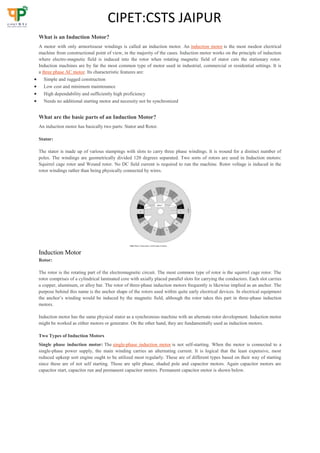
  • 1. CIPET:CSTS JAIPUR What is an Induction Motor? A motor with only armortisseur windings is called an induction motor. An induction motor is the most modest electrical machine from constructional point of view, in the majority of the cases. Induction motor works on the principle of induction where electro-magnetic field is induced into the rotor when rotating magnetic field of stator cuts the stationary rotor. Induction machines are by far the most common type of motor used in industrial, commercial or residential settings. It is a three phase AC motor. Its characteristic features are:  Simple and rugged construction  Low cost and minimum maintenance  High dependability and sufficiently high proficiency  Needs no additional starting motor and necessity not be synchronized What are the basic parts of an Induction Motor? An induction motor has basically two parts: Stator and Rotor. Stator: The stator is made up of various stampings with slots to carry three phase windings. It is wound for a distinct number of poles. The windings are geometrically divided 120 degrees separated. Two sorts of rotors are used in Induction motors: Squirrel cage rotor and Wound rotor. No DC field current is required to run the machine. Rotor voltage is induced in the rotor windings rather than being physically connected by wires. Induction Motor Rotor: The rotor is the rotating part of the electromagnetic circuit. The most common type of rotor is the squirrel cage rotor. The rotor comprises of a cylindrical laminated core with axially placed parallel slots for carrying the conductors. Each slot carries a copper, aluminum, or alloy bar. The rotor of three-phase induction motors frequently is likewise implied as an anchor. The purpose behind this name is the anchor shape of the rotors used within quite early electrical devices. In electrical equipment the anchor’s winding would be induced by the magnetic field, although the rotor takes this part in three-phase induction motors. Induction motor has the same physical stator as a synchronous machine with an alternate rotor development. Induction motor might be worked as either motors or generator. On the other hand, they are fundamentally used as induction motors. Two Types of Induction Motors Single phase induction motor: The single-phase induction motor is not self-starting. When the motor is connected to a single-phase power supply, the main winding carries an alternating current. It is logical that the least expensive, most reduced upkeep sort engine ought to be utilized most regularly. These are of different types based on their way of starting since these are of not self starting. Those are split phase, shaded pole and capacitor motors. Again capacitor motors are capacitor start, capacitor run and permanent capacitor motors. Permanent capacitor motor is shown below.
  • 2. CIPET:CSTS JAIPUR In these types of motors the start winding can have a series capacitor and/or a centrifugal switch. When the supply voltage is applied, current in the main winding lags the supply voltage because of the main winding impedance. And current in the start winding leads/lags the supply voltage depending on the starting mechanism impedance. The angel between the two windings is sufficient phase difference to provide a rotating magnitude field to produce a starting torque. The point when the motor reaches 70% to 80% of synchronous speed, a centrifugal switch on the motor shaft opens and disconnects the starting winding. Applications of Single Phase Induction Motor These are used in low power applications and widely used in domestic applications as well as industrial. And some of those are mentioned below  Pumps  Compressors  Small fans  Mixers  Toys  High speed vacuum cleaners  Electric shavers  Drilling machines Three-Phase Induction Motor: These motors are self-starting and use no capacitor, start winding, centrifugal switch or other starting device. Three-phase AC induction motors are widely used in industrial and commercial applications. These are of two types, squirrel cage and slip ring motors. Squirrel cage motors are widely used due to their rugged construction and simple design. Slip ring motors require external resistors to have high starting torque. Induction motors are used in industry and domestic appliances because these are rugged in construction requiring hardly any maintenance, that they are comparatively cheap, and require supply only to the stator. Applications of Three Phase Induction Motor  Lifts  Cranes  Hoists  Large capacity exhaust fans  Driving lathe machines  Crushers  Oil extracting mills  Textile and etc. Advantages of Induction Motor The motor construction and the way electric power is supplied all give the induction motor several advantages is shown in figure below. And let’s see of them in brief.
  • 3. CIPET:CSTS JAIPUR Advantages of Induction Motor Low cost: Induction machines are very cheap when compared to synchronous and DC motors. This is due to the modest design of induction motor. Therefore, these motors are overwhelmingly preferred for fixed speed applications in industrial applications and for commercial and domestic applications where AC line power can be easily attached. Low maintenance cost: Induction motors are maintenance free motors unlike dc motors and synchronous motors. The construction of induction motor is very simple and hence maintenance is also easy, resulting in low maintenance cost. Ease of operation: Operation of induction motor is very simple because there is no electrical connector to the rotor that supply power and current is induced by the movement of the transformer performs on the rotor due to the low resistance of the rotating coils. Induction motors are self start motors. This can result in reducing the effort needed for maintenance. Speed Variation: The speed variation of induction motor is nearly constant. The speed typically varies only by a few percent going from no load to rated load. High starting torque: The staring torque of induction motor is very high which makes motor useful for operations where load is applied before the starting of the motor.3 phase induction motors will have self starting torque unlike synchronous motors. However, single-phase induction motors does not have self starting torque and are made to rotate using some auxiliaries. Durability: Another major advantage an induction motor is that it is durability. This makes it the ideal machine for many uses. This results the motor to run for many years with no cost and maintenance. All these advantages make induction motor to use in many applications such as industrial, domestic and in many applications. Definition ofSlip RingMotor The motor which employing the wound rotor is known as a slip ring induction motor or phase wound motor. It consists laminated cylindrical core which has a semi-closed slot at the outer periphery and carries three-phase insulated winding. The rotor is wound for the same number of poles as that of the stator. The three finish terminals are connected forming star point, and the three start terminals are connected to three copper slip rings fixed on the shaft. The mild steel shaft is passed through the centre of the rotor and fixed to the key. The purpose of the shaft is to send mechanical power. Definition ofSquirrel CageMotor The motor which employing squirrel cage type rotor is known as the squirrel cage motor. The construction of the rotor is rugged and simple. The rotor of the motor consists the cylindrical laminated core having semi-closed circular slots and short
  • 4. CIPET:CSTS JAIPUR circuit at each end by copper or aluminium ring, called short circuiting ring. It is not possible to add any external resistance in the rotor of the circuit. The rotor slots are not parallel but are skewed. The skewing of the rotor has the following advantages. 1. Its reduces humming and thus ensuring the quiet running of a motor. 2. The skewed rotor gives smooth torque curves for different positions of the rotor. 3. It reduces the magnetic locking of the stator and rotor. 4. It increases the rotor resistance due to the increased length of the rotor bar conductors. KeyDifferences Between Slip Ring &Squirrel Cage Induction Motor 1. The motor whose rotor is wound type such type of motor is called slip ring induction motor, whereas the squirrel cage motor, has a squirrel cage type rotor. 2. The rotor of the slip ring motor has a cylindrical core with parallel slots, and each slot consists each bar. The slot of the squirrel cage motor is not parallel to each other. 3. The slip ring motor is also called phase wound rotor. The another name of the squirrel cage motor is cage motor. 4. The construction of the slip-ring motor is complicated because it consists slip ring and brushes whereas the construction of the squirrel cage motor is simple. 5. The phase wound motor consists external resistance circuit, whereas in squirrel cage motor it is not possible to add any external resistance circuit because their rotor bars are permanently slotted. 6. For starting the slip ring motor the rotor resistance starter is used, whereas the slip ring motor does not require any starter. 7. The starting torque of the slip-ring motor is high, whereas in squirrel cage motor it is low. 8. The maintenance cost of the slip ring motor is high as compared to squirrel cage motor because the slip ring motor consists brushes and rings. 9. The copper loss is more in slip ring motor as compared to squirrel cage motor. 10. The slip ring motor has brushes for transferring the power whereas the squirrel cage motor is brushless. 11. The copper loss in the phase wound motor is high as compared to squirrel cage motor. 12. The efficiency of the slip ring motor is low whereas the squirrel cage motor has high efficiency. 13. The speed of the phase wound motor is controlled by using the resistance circuit. It is impossible to control the speed of the squirrel cage motor. 14. The slip ring motor has low power factor as compared to squirrel cage motor. 15. The cost of the phase wound rotor is high because it consists brushes. The squirrel cage motor is cheap. 16. The starting current of the phase wound rotor is low because it is controlled by resistance circuit whereas it is high in squirrel cage motor. 17. The phase wound motor is mostly used in places where high starting torque is required like a hoist, cranes, etc. The squirrel cage motor is used in a drilling machine, lathe machine, etc., The overloading capacity of the slip ring motor is high as compared to squirrel cage motor and it is smoothly running under heavy loads. It is less sensitive and also has no abnormal heating during the starting.
  • 5. CIPET:CSTS JAIPUR Working of Air Circuit Breaker and Its Applications Air Circuit Breaker (ACB) is an electrical device used to provide Overcurrent and short-circuit protection for electric circuits over 800 Amps to 10K Amps. These are usually used in low voltage applications below 450V. We can find these systems in Distribution Panels (below 450V). Here in this article, we will discuss the working of Air Circuit Breaker. Air circuit breaker is circuit operation breaker that operates in the air as an arc extinguishing medium, at a given atmospheric pressure. There are several types of Air circuit breakers and switching gears available in the market today that is durable, high-performing, easy to install and maintain. The air circuit breakers have completely replaced oil circuit breakers. Air Circuit Breaker Working Air circuit breakers operate with their contacts in free air. Their method of arc quenching control is entirely different from that of oil circuit-breakers. They are always used for a low-voltage interruption and now tends to replace high-voltage oil breakers. The below-shown figure illustrates the principle of air breaker circuit operation. Air Break Circuit Breaker Interruption Air Circuit breakers generally have two pairs of contacts. The main pair of contacts (1) carries the current at normal load and these contacts are made of copper metal. The second pair is the arcing contact (2) and is made of carbon. When the circuit breaker is being opened, the main contacts open first. When the main contacts opened the arcing contacts are still in touch with each other. As the current gets a parallel low resistive path through the arcing contact. During the opening of main contacts, there will not be any arcing in the main contact. The arcing is only initiated when finally the arcing contacts are separated. The each of the arc contacts is fitted with an arc runner which helps. The arc discharge to move upward due to both thermal and electromagnetic effects as shown in the figure. As the arc is driven upward it enters in the arc chute, consisting of splatters. The arc in the chute will become colder, lengthen and split hence arc voltage becomes much larger than the system voltage at the time of operation of air circuit breaker, and therefore the arc is extinguished finally during the current zero. The air brake circuit box is made of insulating and fireproof material and it is divided into different sections by the barriers of the same material, as shown above, figure (a). At the bottom of each barrier is a small metal conducting element between one side of the barrier and the other. When the arc, driven upwards by the electromagnetic forces, enters the bottom of the chute, it is split into many sections by the barriers, but the each metal piece ensures electrical continuity between the arcs in each section, the several arcs are consequently in the series. The electromagnetic forces within each and every section of the chute cause the arc in that section to start the form of a helix, as shown above, figure (b). All these helices are in series so that the total length of the arc has been greatly extended, and its resistance is abundantly increased. This will affect the current reduction in the circuit. Figure (a) shows the development of the arc from the time it leaves the main contacts until it is within the arc chute. When the current next ceases at a current zero, the ionised air in the path of where the arc had been being in parallel with the open contacts and acts as a shunt resistance across both the contacts and the self-capacitance C, shown in below figure with red as a high resistance R.
  • 6. CIPET:CSTS JAIPUR When the oscillation starts between C and L as described for the idealised circuit breaker shown in Figure below, this resistance damps the oscillation heavily. Certainly, it is usually so heavy that the damping is critical, the oscillation cannot then take place at all, and the restriking voltage, instead of appearing as a high-frequency oscillation, rises dead-beat to its eventual value of peak generator voltage. This is shown below the lower waveform. Applications of Air Circuit Breakers Air Circuit Breakers are used for controlling the power station auxiliaries and industrial plants. They offer protection to industrial plants, electrical machines like the transformers, capacitors, and generators.  They are mainly used for protection of plants, where there are possibilities of fire or explosion hazards.  The air brake principle of the air breaker circuit arc is used in DC circuits and AC circuits up to 12KV.  The air circuit breakers have high resistance power that helps in increasing the resistance of the arc by splitting, cooling and lengthening.  Air circuit breaker is also used in the Electricity sharing system and NGD about 15kV MCB-Miniature Circuit Breaker MCB is an electromechanical device which guards an electrical circuit from an over current, that may effect from short circuit, overload or imperfect design. This is a better option to a Fuse since it doesn’t require alternate once an overload is identified. An MCB can be simply rearranged and thus gives a better operational protection and greater handiness without incurring huge operating cost. The operating principle of MCB is simple.
  • 7. CIPET:CSTS JAIPUR Miniature Circuit Breaker An MCB function by interrupting the stability of electrical flow through the circuit once an error is detected. In simple conditions this circuit breaker is a switch which routinely turns off when the current flows through it and passes the maximum acceptable limit. Generally, these are designed to guard against over current and overheating. MCB is substituting the rewirable switch-fuse units for low power domestic and industrial applications in a very quick manner. In wiring system, the MCB is a blend of all three functions such as protection of short circuit, overload and switching. Protection of overload by using a bimetallic strip & short circuit protection by used solenoid. These are obtainable in different pole versions like single, double, triple pole & four poles with neutral poles if necessary. The normal current rating is ranges from 0.5-63 A with a symmetrical short circuit breaking capacity of 3-10 KA, at a voltage level of 230 or 440V. Characteristics of MCB The characteristics of an MCB mainly include the following  Rated current is not more than 100 amperes  Normally, trip characteristics are not adjustable  Thermal/thermal magnetic operation Limit switch In electrical engineering a limit switch is a switch operated by the motion of a machine part or presence of an object. They are used for controlling machinery as part of a control system, as a safety interlocks, or to count objects passing a point. A limit switch is an electromechanical device that consists of an actuator mechanically linked to a set of contacts. When an object comes into contact with the actuator, the device operates the contacts to make or break an electrical connection. Limit switches are used in a variety of applications and environments because of their ruggedness, ease of installation, and reliability of operation. They can determine the presence or absence, passing, positioning, and end of travel of an object. They were first used to define the limit of travel of an object; hence the name "Limit Switch". A limit switch with a roller-lever operator; this is installed on a gate on a canal lock, and indicates the position of a gate to a control system. Standardized limit switches are industrial control components manufactured with a variety of operator types, including lever, roller plunger, and whisker type. Limit switches may be directly mechanically operated by the motion of the operating lever. A reed switch may be used to indicate proximity of a magnet mounted on some moving part. Proximity switches operate by the disturbance of an electromagnetic field, by capacitance, or by sensing a magnetic field. Rarely, a final operating device such as a lamp or solenoid valve will be directly controlled by the contacts of an industrial limit switch, but more typically the limit switch will be wired through a control relay, a motor contactor control circuit, or as an input to a programmable logic controller. Miniature snap-action switch may be used for example as components of such devices as photocopiers, computer printers, convertible tops or microwave ovens to ensure internal components are in the correct position for operation and to prevent operation when access doors are opened. A set of adjustable limit switches are installed on a garage door opener to shut off the motor when the door has reached the fully raised or fully lowered position. A numerical control machine such as
  • 8. CIPET:CSTS JAIPUR a lathe will have limit switches to identify maximum limits for machine parts or to provide a known reference point for incremental motions. Thermocouple A thermocouple is an electrical device consisting of two dissimilar electrical conductors forming electrical junctions at differing temperatures. A thermocouple produces a temperature-dependent voltage as a result of the thermoelectric effect, and this voltage can be interpreted to measure temperature. Thermocouples are a widely used type of temperature sensor. Commercial thermocouples are inexpensive, interchangeable, are supplied with standard connectors, and can measure a wide range of temperatures. In contrast to most other methods of temperature measurement, thermocouples are self powered and require no external form of excitation. The main limitation with thermocouples is accuracy; system errors of less than one degree Celsius (°C) can be difficult to achieve. Types Certain combinations of alloys have become popular as industry standards. Selection of the combination is driven by cost, availability, convenience, melting point, chemical properties, stability, and output. Different types are best suited for different applications. They are usually selected on the basis of the temperature range and sensitivity needed. Thermocouples with low sensitivities (B, R, and S types) have correspondingly lower resolutions. Other selection criteria include the chemical inertness of the thermocouple material and whether it is magnetic or not. Standard thermocouple types are listed below with the positive electrode first, followed by the negative electrode. Nickel-alloy thermocouples Characteristic functions for thermocouples that reach intermediate temperatures, as covered by nickel-alloy thermocouple types E, J, K, M, N, T. Also shown are the noble-metal alloy type P and the pure noble-metal combinations gold–platinum and platinum–palladium. Type E Type E (chromel–constantan) has a high output (68 µV/°C), which makes it well suited to cryogenic use. Additionally, it is non-magnetic. Wide range is −50 °C to +740 °C and narrow range is −110 °C to +140 °C. Type J Type J (iron–constantan) has a more restricted range (−40 °C to +750 °C) than type K but higher sensitivity of about 50 µV/°C.[2] The Curie point of the iron (770 °C)[9] causes a smooth change in the characteristic, which determines the upper temperature limit. Type K Type K (chromel–alumel) is the most common general-purpose thermocouple with a sensitivity of approximately 41 µV/°C.[10] It is inexpensive, and a wide variety of probes are available in its −200 °C to +1350 °C (−330 °F to +2460 °F) range. Type K was specified at a time when metallurgy was less advanced than it is today, and consequently characteristics may vary considerably between samples. One of the constituent metals, nickel, is magnetic; a characteristic of thermocouples made with magnetic material is that they undergo a deviation in output when the material reaches its Curie point, which occurs for type K thermocouples at around 185 °C. They operate very well in oxidizing atmospheres. If, however, a mostly reducing atmosphere (such as hydrogen with a small amount of oxygen) comes into contact with the wires, the chromium in the chromel alloy oxidizes. This reduces the emf
  • 9. CIPET:CSTS JAIPUR output, and the thermocouple reads low. This phenomenon is known as green rot, due to the color of the affected alloy. Although not always distinctively green, the chromel wire will develop a mottled silvery skin and become magnetic. An easy way to check for this problem is to see whether the two wires are magnetic (normally, chromel is non-magnetic). Hydrogen in the atmosphere is the usual cause of green rot. At high temperatures, it can diffuse through solid metals or an intact metal thermowell. Even a sheath of magnesium oxide insulating the thermocouple will not keep the hydrogen out. Type M Type M are used in vacuum furnaces for the same reasons as with type C (described below). Upper temperature is limited to 1400 °C. It is less commonly used than other types. Type N Type N (Nicrosil–Nisil) thermocouples are suitable for use between −270 °C and +1300 °C, owing to its stability and oxidation resistance. Sensitivity is about 39 µV/°C at 900 °C, slightly lower compared to type K. Designed at the Defence Science and Technology Organisation (DSTO) of Australia, by Noel A. Burley, type-N thermocouples overcome the three principal characteristic types and causes of thermoelectric instability in the standard base- metal thermoelement materials: 1. A gradual and generally cumulative drift in thermal EMF on long exposure at elevated temperatures. This is observed in all base-metal thermoelement materials and is mainly due to compositional changes caused by oxidation, carburization, or neutron irradiationthat can produce transmutation in nuclear reactor environments. In the case of type-K thermocouples, manganese and aluminium atoms from the KN (negative) wire migrate to the KP (positive) wire, resulting in a down-scale drift due to chemical contamination. This effect is cumulative and irreversible. 2. A short-term cyclic change in thermal EMF on heating in the temperature range about 250–650 °C, which occurs in thermocouples of types K, J, T, and E. This kind of EMF instability is associated with structural changes such as magnetic short-range order in the metallurgical composition. 3. A time-independent perturbation in thermal EMF in specific temperature ranges. This is due to composition- dependent magnetic transformations that perturb the thermal EMFs in type-K thermocouples in the range about 25–225 °C, and in type J above 730 °C. The Nicrosil and Nisil thermocouple alloys show greatly enhanced thermoelectric stability relative to the other standard base-metal thermocouple alloys because their compositions substantially reduce the thermoelectric instabilities described above. This is achieved primarily by increasing component solute concentrations (chromium and silicon) in a base of nickel above those required to cause a transition from internal to external modes of oxidation, and by selecting solutes (silicon and magnesium) that preferentially oxidize to form a diffusion-barrier, and hence oxidation-inhibiting films. Type T Type T (copper–constantan) thermocouples are suited for measurements in the −200 to 350 °C range. Often used as a differential measurement, since only copper wire touches the probes. Since both conductors are non-magnetic, there is no Curie point and thus no abrupt change in characteristics. Type-T thermocouples have a sensitivity of about 43 µV/°C. Note that copper has a much higher thermal conductivity than the alloys generally used in thermocouple constructions, and so it is necessary to exercise extra care with thermally anchoring type-T thermocouples. Platinum/rhodium-alloy thermocouples Characteristic functions for high-temperature thermocouple types, showing Pt/Rh, W/Re, Pt/Mo, and Ir/Rh-alloy thermocouples. Also shown is the Pt–Pd pure-metal thermocouple.
  • 10. CIPET:CSTS JAIPUR Types B, R, and S thermocouples use platinum or a platinum/rhodium alloy for each conductor. These are among the most stable thermocouples, but have lower sensitivity than other types, approximately 10 µV/°C. Type B, R, and S thermocouples are usually used only for high-temperature measurements due to their high cost and low sensitivity. Type B Type B thermocouples are suited for use at up to 1800 °C. Type-B thermocouples produce the same output at 0 °C and 42 °C, limiting their use below about 50 °C. The emf function has a minimum around 21 °C, meaning that cold-junction compensation is easily performed, since the compensation voltage is essentially a constant for a reference at typical room temperatures. Type R Type R thermocouples are used 0 to 1600 °C. Type S Type S thermocouples, similar to type R, are used up to 1600 °C. Before the introduction of the International Temperature Scale of 1990 (ITS-90), precision type-S thermocouples were used as the practical standard thermometers for the range of 630 °C to 1064 °C, based on an interpolation between the freezing points of antimony, silver, and gold. Starting with ITS- 90, platinum resistance thermometers have taken over this range as standard thermometers. Relay A relay is an electrically operated switch. Many relays use an electromagnet to mechanically operate a switch, but other operating principles are also used, such as solid-state relays. Relays are used where it is necessary to control a circuit by a separate low-power signal, or where several circuits must be controlled by one signal. The first relays were used in long distance telegraph circuits as amplifiers: they repeated the signal coming in from one circuit and re-transmitted it on another circuit. Relays were used extensively in telephone exchanges and early computers to perform logical operations. A type of relay that can handle the high power required to directly control an electric motor or other loads is called a contactor. Solid-state relays control power circuits with no moving parts, instead using a semiconductor device to perform switching. Relays with calibrated operating characteristics and sometimes multiple operating coils are used to protect electrical circuits from overload or faults; in modern electric power systems these functions are performed by digital instruments still called "protective relays". Magnetic latching relays require one pulse of coil power to move their contacts in one direction, and another, redirected pulse to move them back. Repeated pulses from the same input have no effect. Magnetic latching relays are useful in applications where interrupted power should not be able to transition the contacts. Magnetic latching relays can have either single or dual coils. On a single coil device, the relay will operate in one direction when power is applied with one polarity, and will reset when the polarity is reversed. On a dual coil device, when polarized voltage is applied to the reset coil the contacts will transition. AC controlled magnetic latch relays have single coils that employ steering diodes to differentiate between operate and reset commands. Types Coaxial relay Where radio transmitters and receivers share one antenna, often a coaxial relay is used as a TR (transmit-receive) relay, which switches the antenna from the receiver to the transmitter. This protects the receiver from the high power of the transmitter. Such relays are often used in transceivers which combine transmitter and receiver in one unit. The relay contacts are designed not to reflect any radio frequency power back toward the source, and to provide very high isolation between receiver and transmitter terminals. The characteristic impedance of the relay is matched to the transmission line impedance of the system, for example, 50 ohms. Contactor A contactor is a heavy-duty relay with higher current ratings, used for switching electric motors and lighting loads. Continuous current ratings for common contactors range from 10 amps to several hundred amps. High-current contacts are made with alloys containing silver. The unavoidable arcing causes the contacts to oxidize; however, silver oxide is still a good conductor. Contactors with overload protection devices are often used to start motors. Force-guided contacts relay A 'force-guided contacts relay' has relay contacts that are mechanically linked together, so that when the relay coil is energized or de-energized, all of the linked contacts move together. If one set of contacts in the relay becomes immobilized,
  • 11. CIPET:CSTS JAIPUR no other contact of the same relay will be able to move. The function of force-guided contacts is to enable the safety circuit to check the status of the relay. Force-guided contacts are also known as "positive-guided contacts", "captive contacts", "locked contacts", "mechanically linked contacts", or "safety relays". These safety relays have to follow design rules and manufacturing rules that are defined in one main machinery standard EN 50205 : Relays with forcibly guided (mechanically linked) contacts. These rules for the safety design are the one that are defined in type B standards such as EN 13849-2 as Basic safety principles and Well-tried safety principles for machinery that applies to all machines. Force-guided contacts by themselves can not guarantee that all contacts are in the same state, however they do guarantee, subject to no gross mechanical fault, that no contacts are in opposite states. Otherwise, a relay with several normally open (NO) contacts may stick when energised, with some contacts closed and others still slightly open, due to mechanical tolerances. Similarly, a relay with several normally closed (NC) contacts may stick to the unenergised position, so that when energised, the circuit through one set of contacts is broken, with a marginal gap, while the other remains closed. By introducing both NO and NC contacts, or more commonly, changeover contacts, on the same relay, it then becomes possible to guarantee that if any NC contact is closed, all NO contacts are open, and conversely, if any NO contact is closed, all NC contacts are open. It is not possible to reliably ensure that any particular contact is closed, except by potentially intrusive and safety-degrading sensing of its circuit conditions, however in safety systems it is usually the NO state that is most important, and as explained above, this is reliably verifiable by detecting the closure of a contact of opposite sense. Force-guided contact relays are made with different main contact sets, either NO, NC or changeover, and one or more auxiliary contact sets, often of reduced current or voltage rating, used for the monitoring system. Contacts may be all NO, all NC, changeover, or a mixture of these, for the monitoring contacts, so that the safety system designer can select the correct configuration for the particular application. Safety relays are used as part of an engineered safety system. Latching relay Latching relay with permanent magnet A latching relay (also called "latch", "impulse", "bistable", "keep", or "stay" relays) maintains either contact position indefinitely without power applied to the coil. The advantage is that one coil consumes power only for an instant while the relay is being switched, and the relay contacts retain this setting across a power outage. A latching relay allows remote control of building lighting without the hum that may be produced from a continuously (AC) energized coil. In one mechanism, two opposing coils with an over-center spring or permanent magnet hold the contacts in position after the coil is de-energized. A pulse to one coil turns the relay on and a pulse to the opposite coil turns the relay off. This type is widely used where control is from simple switches or single-ended outputs of a control system, and such relays are found in avionics and numerous industrial applications. Another latching type has a remanent core that retains the contacts in the operated position by the remanent magnetism in the core. This type requires a current pulse of opposite polarity to release the contacts. A variation uses a permanent magnet that produces part of the force required to close the contact; the coil supplies sufficient force to move the contact open or closed by aiding or opposing the field of the permanent magnet. A polarity controlled relay needs changeover switches or an H bridge drive circuit to control it. The relay may be less expensive than other types, but this is partly offset by the increased costs in the external circuit. In another type, a ratchet relay has a ratchet mechanism that holds the contacts closed after the coil is momentarily energized. A second impulse, in the same or a separate coil, releases the contacts. This type may be found in certain cars, for headlamp dipping and other functions where alternating operation on each switch actuation is needed. A stepping relay is a specialized kind of multi-way latching relay designed for early automatic telephone exchanges. An earth leakage circuit breaker includes a specialized latching relay. Very early computers often stored bits in a magnetically latching relay, such as ferreed or the later remreed in the 1ESS switch.
  • 12. CIPET:CSTS JAIPUR Some early computers used ordinary relays as a kind of latch—they store bits in ordinary wire spring relays or reed relays by feeding an output wire back as an input, resulting in a feedback loop or sequential circuit. Such an electrically latching relay requires continuous power to maintain state, unlike magnetically latching relays or mechanically racheting relays. In computer memories, latching relays and other relays were replaced by delay line memory, which in turn was replaced by a series of ever-faster and ever-smaller memory technologies. Machine tool relay A machine tool relay is a type standardized for industrial control of machine tools, transfer machines, and other sequential control. They are characterized by a large number of contacts (sometimes extendable in the field) which are easily converted from normally open to normally closed status, easily replaceable coils, and a form factor that allows compactly installing many relays in a control panel. Although such relays once were the backbone of automation in such industries as automobile assembly, the programmable logic controller(PLC) mostly displaced the machine tool relay from sequential control applications. A relay allows circuits to be switched by electrical equipment: for example, a timer circuit with a relay could switch power at a preset time. For many years relays were the standard method of controlling industrial electronic systems. A number of relays could be used together to carry out complex functions (relay logic). The principle of relay logic is based on relays which energize and de-energize associated contacts. Relay logic is the predecessor of ladder logic, which is commonly used in programmable logic controllers. Mercury relay A mercury relay is a relay that uses mercury as the switching element. They are used where contact erosion would be a problem for conventional relay contacts. Owing to environmental considerations about significant amount of mercury used and modern alternatives, they are now comparatively uncommon. Mercury-wetted relay A mercury-wetted reed relay A mercury-wetted reed relay is a form of reed relay in which the contacts are wetted with mercury. Such relays are used to switch low-voltage signals (one volt or less) where the mercury reduces the contact resistance and associated voltage drop, for low-current signals where surface contamination may make for a poor contact, or for high-speed applications where the mercury eliminates contact bounce. Mercury wetted relays are position-sensitive and must be mounted according to the manufacturer's specifications to work properly. Because of the toxicity and expense of liquid mercury, these relays are now rarely used. The mercury-wetted relay has one particular advantage, in that the contact closure appears to be virtually instantaneous, as the mercury globules on each contact coalesce. The current rise time through the contacts is generally considered to be a few picoseconds, however in a practical circuit it will be limited by the inductance of the contacts and wiring. It was quite common, before the restrictions on the use of mercury, to use a mercury-wetted relay in the laboratory as a convenient means of generating fast rise time pulses, however although the rise time may be picoseconds, the exact timing of the event is, like all other types of relay, subject to considerable jitter, possibly milliseconds, due to mechanical imperfections. The same coalescence process causes another effect, which is a nuisance in some applications. The contact resistance is not stable immediately after contact closure, and drifts, mostly downwards, for several seconds after closure, the change perhaps being 0.5 ohm. Multi-voltage relays Multi-voltage relays are devices designed to work for wide voltage ranges such as 24 to 240 VAC and VDC and wide frequency ranges such as 0 to 300 Hz. They are indicated for use in installations that do not have stable supply voltages.
  • 13. CIPET:CSTS JAIPUR Overload protection relay Electric motors need overcurrent protection to prevent damage from over-loading the motor, or to protect against short circuits in connecting cables or internal faults in the motor windings. The overload sensing devices are a form of heat operated relay where a coil heats a bimetallic strip, or where a solder pot melts, to operate auxiliary contacts. These auxiliary contacts are in series with the motor's contactor coil, so they turn off the motor when it overheats. This thermal protection operates relatively slowly allowing the motor to draw higher starting currents before the protection relay will trip. Where the overload relay is exposed to the same ambient temperature as the motor, a useful though crude compensation for motor ambient temperature is provided. The other common overload protection system uses an electromagnet coil in series with the motor circuit that directly operates contacts. This is similar to a control relay but requires a rather high fault current to operate the contacts. To prevent short over current spikes from causing nuisance triggering the armature movement is damped with a dashpot. The thermal and magnetic overload detections are typically used together in a motor protection relay.[citation needed] Electronic overload protection relays measure motor current and can estimate motor winding temperature using a "thermal model" of the motor armature system that can be set to provide more accurate motor protection. Some motor protection relays include temperature detector inputs for direct measurement from a thermocouple or resistance thermometer sensor embedded in the winding.[citation needed] Polarized relay A polarized relay places the armature between the poles of a permanent magnet to increase sensitivity. Polarized relays were used in middle 20th Century telephone exchanges to detect faint pulses and correct telegraphic distortion. Reed relay Top, middle: reed switches, bottom: reed relay A reed relay is a reed switch enclosed in a solenoid. The switch has a set of contacts inside an evacuated or inert gas-filled glass tube which protects the contacts against atmospheric corrosion; the contacts are made of magneticmaterial that makes them move under the influence of the field of the enclosing solenoid or an external magnet. Reed relays can switch faster than larger relays and require very little power from the control circuit. However, they have relatively low switching current and voltage ratings. Though rare, the reeds can become magnetized over time, which makes them stick 'on' even when no current is present; changing the orientation of the reeds with respect to the solenoid's magnetic field can resolve this problem. Sealed contacts with mercury-wetted contacts have longer operating lives and less contact chatter than any other kind of relay.[21] Safety relays Safety relays are devices which generally implement safety functions. In the event of a hazard, the task of such a safety function is to use appropriate measures to reduce the existing risk to an acceptable level. Solid-state contactor A solid-state contactor is a heavy-duty solid state relay, including the necessary heat sink, used where frequent on-off cycles are required, such as with electric heaters, small electric motors, and lighting loads. There are no moving parts to wear out and there is no contact bounce due to vibration. They are activated by AC control signals or DC control signals from programmable logic controllers (PLCs), PCs, transistor-transistor logic (TTL) sources, or other microprocessor and microcontroller controls.
  • 14. CIPET:CSTS JAIPUR Solid-state relay 25 A and 40 A solid state contactors A solid-state relay (SSR) is a solid state electronic component that provides a function similar to an electromechanical relay but does not have any moving components, increasing long-term reliability. A solid-state relay uses a thyristor, TRIAC or other solid-state switching device, activated by the control signal, to switch the controlled load, instead of a solenoid. An optocoupler (a light-emitting diode (LED) coupled with a photo transistor) can be used to isolate control and controlled circuits.[citation needed] Static relay A static relay consists of electronic circuitry to emulate all those characteristics which are achieved by moving parts in an electro-magnetic relay. Time delay relay Timing relays are arranged for an intentional delay in operating their contacts. A very short (a fraction of a second) delay would use a copper disk between the armature and moving blade assembly. Current flowing in the disk maintains magnetic field for a short time, lengthening release time. For a slightly longer (up to a minute) delay, a dashpot is used. A dashpot is a piston filled with fluid that is allowed to escape slowly; both air-filled and oil-filled dashpots are used. The time period can be varied by increasing or decreasing the flow rate. For longer time periods, a mechanical clockwork timer is installed. Relays may be arranged for a fixed timing period, or may be field adjustable, or remotely set from a control panel. Modern microprocessor-based timing relays provide precision timing over a great range. Some relays are constructed with a kind of "shock absorber" mechanism attached to the armature which prevents immediate, full motion when the coil is either energized or de-energized. This addition gives the relay the property of time-delay actuation. Time-delay relays can be constructed to delay armature motion on coil energization, de-energization, or both. Time-delay relay contacts must be specified not only as either normally open or normally closed, but whether the delay operates in the direction of closing or in the direction of opening. The following is a description of the four basic types of time-delay relay contacts. First we have the normally open, timed-closed (NOTC) contact. This type of contact is normally open when the coil is unpowered (de-energized). The contact is closed by the application of power to the relay coil, but only after the coil has been continuously powered for the specified amount of time. In other words, the direction of the contact's motion (either to close or to open) is identical to a regular NO contact, but there is a delay in closing direction. Because the delay occurs in the direction of coil energization, this type of contact is alternatively known as a normally open, on-delay.
  • 15. CIPET:CSTS JAIPUR Vacuum relays A sensitive relay having its contacts mounted in a highly evacuated glass housing, to permit handling radio-frequency voltages as high as 20,000 volts without flashover between contacts even though contact spacing is but a few hundredths of an inch when open.