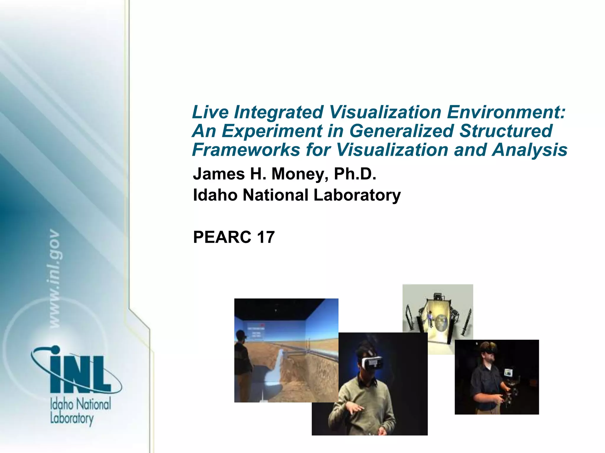
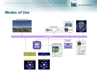
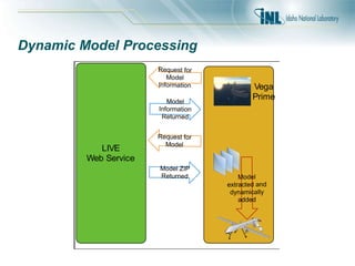
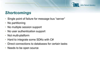
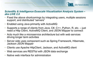
Live Integrated Visualization Environment:
An Experiment in Generalized Structured
Frameworks for Visualization and Analysis
James H. Money, Ph.D.
Idaho National Laboratory
PEARC 17
Contents
• Background
– Problem Environment
– Past Approaches/Goals
• Live Integrate Visualization Environment
– Data Feeds/Input Connectors
– Output Connectors
– Technical & System Details
– Initial Application
– Driver Details
• Output Connector Process
– Modes of Use
– Dynamic Model Processing
• Shortcomings
• SIEVAS
• Accomplishments
• Examples
Background
• Joint Intelligence Laboratory (JIL) – built in 2006 as a rapid test bed for end-to-end
intelligence solutions for Department of Defense (DoD)
• Initially based on the Joint Intelligence Operations Center Experimental (JIOC-X)
developed early 2000s
• Built to test, experiment and train using real operational data
• Supported a number of advanced visualization systems including:
– Knowledge Wall
– Tabletop Touch Displays
– Stereo Wall
– Knowledge Advanced Visualization Environment (KAVE) – A CAVE by another
name
• Joined the JIL in late 2007
• During 2008 installed a new CAVE that is 18’x10’x10’ – largest in DoD at the time
Problem Environment
• DoD has invested in over 18 CAVEs now, mostly used for modeling and simulation and
intelligence work
• Software products used by these groups included:
– Presagis Vega Prime
– Mechdyne vGeo
– Mechdyne Conduit
– GeoTime
– Delta3D
– Google Earth Professional
– And several more…
• Strategy included having the DoD pay for modifications to CAVE-enable the proprietary
tools (high supports costs!)
Problem Environment
• Various groups were attempting to process and analyze data in real
time with these and other production systems
• Approaches varied but all contained some major flaws in execution
• The desire was to ingest real time feeds into all the environments
seamlessly
• Data feeds included Distributed Common Ground System (DCGS),
Global Command and Control System (GCCS), as well as other lessor
know systems
• Showed first prototype of real-time/in-situ visualization with GOTS
systems using DCGS-A and a Force Directed Layout in 2008 – this led
to the development of a framework for more general purpose use
Past Approaches
• Vendor Specific Extensions
– Works out of the box
– Breaks down on larger datasets/Addition cost
• Direct Vendor Modifications
– Costly to install
– Frequently, do not meet 100% of user requirements
• Custom Coding/Toolkits
– Costly to build and maintain
– Custom build for each CAVE
• OpenGL Interceptors
– Usage of desktop applications
– Requires desktop to use, features do not work in immersive
environment
Goals
1. Multi-application and domain area aware
2. Data/Model Abstraction using standard techniques
3. Simultaneous access to same data streams
4. Real-time access with DVR capability
5. Merging of simulated and live data streams
6. Utilization of off-the-shelf products
Live Integrated Visualization Environment
• Live Integrated Visualization Environment (LIVE) is the end-to-end
solution for handling the live feeds while allowing a myriad of software
and tools to visualize the results
• Supported geospatial data as well as non-geospatial data at the design
phase
• Allowed for advanced analytics in the system with verification in the
CAVE (Now called “big data”)
• Allowed for live viewing, recording, playback and manipulation of data
• Permits remote viewing to phones, tablets and other types of displays
LIVE
• Built on idea of “connectors”
• Utilized input connectors for importing and storing data
• Utilized output connectors for visualization of results
• All the components were loosely coupled and connected by a
data/message bus
• Everything was distributed out of the box
• This allows products such as Google Earth to have local data sources
without changes
LIVE
GeoTime
vGeo
Google Earth
Vega Prime
LIVE Data Feeds
• DCGS-A (ESRI Map Server)
• GCCS Tactical Management Server (TMS)
• Link 16
• Distributed Interactive Simulation (DIS)/High Level Architecture (HLA)
• Cursor-on-Target (CoT)
• System Toolkit (STK)
Live Output Connectors
• Vega Prime Modules (display, control, and loading/saving)
• Google Earth KML feed
• Force Directed Layout (FDL)
• GeoJSON for GeoTime
Technical Details
• Built initial on Microsoft .NET 2.0 -> Later migrate to 3.5
• Data storage used Microsoft SQL Server
• MessageBus custom developed using .NET Remoting
• Combination of reflection, C#, and managed and unmanaged C++ to
connect components
• Contained system information on sessions, data sources, drivers, and
configuration options
• Session
– List of Data Sources -> Associated Driver
• DVRService will load these sessions
• Also possible to use in distributed mode without centralized drivers
• Output connectors required to choose session at startup or pass by
configuration option
System Details
• First developed demo application using System Toolkit for UAV
applications to aid in planning tasks
• Developed Google Earth connector
• DVR Controls developed as desktop application
• Later DVR moved into Vega Prime as billboard controls
• Message bus used a publish-subscribe paradigm for messaging
• Message bus sent both control (for example DVR play, stop, goto) and
messages
Initial Application
LIVE
Message Bus/Web Service
CAVE
KML
Connector
Google
Earth
UAV Tool
VLC Client
Desktop
Configura) on
Tool
Vega Prime
Driver Details
• Components include
– IDriver
– IRecordable
– IPlayable
– ILIVEPlayable – live stream sources only
– ITransformable
Driver Details
Send Details
SendObjects
IDriver
LIVE
Message
Bus
Storage
IRecordable
IPlayable
ILIVEPlayable
ITransformable
Store
Retrive
Densify
DVR
Details
Instantiate
Driver
Output Connector Process
• Process
– Session would load drivers for each data source at startup
– Connect to web service for information about session
– Connect to message bus
– Subscribe to messages of interest – in this case DVR controls and
Platform type messages
– Handling dynamic loading of models in threads
– Show model and changes after model load and thereafter
• Google Earth (using Stand-alone middleware)
– Connect and listen for message
– Keep log of messages
– Generate KML when requested from Google Earth
– KMZ file would request periodic refresh of KML data
Modes of Use
• Two primary modes of use for input: Drivers (Input Connectors) and
Standalone applications
– Drivers allowed automated processing but not real user interaction
at run time
– Standalone – allowed user to change items on the fly; used by the
UAV Tool
• Output similarly two ways to obtain data
– Plugin using native SDK (Vega Prime)
– Standalone application that acted as middleware between the
message bus and the data (Google Earth)
• This allowed swapping of simulated feeds in place of real-time data
connections when network connectivity was limited. (For example,
static vs. live full motion video (FMV) feeds)
• Chaining with multiple instances for data analytics
Modes of Use
Dynamic Model Processing
LIVE
Web Service
Request for
Model
Information
Model
Information
Returned
Request for
Model
Model ZIP
Returned Model
extracted and
dynamically
added
Vega
Prime
Shortcomings
• Single point of failure for message bus “server”
• No partitioning
• No multiple session support
• No user authentication support
• Not multi-platform
• Hard to integrate some SDKs with C#
• Direct connections to databases for certain tasks
• Needs to be open source
Scientific & Intelligence Exascale Visualization Analysis System –
aka LIVE 2.0
• Fixed the above shortcomings by integrating users, multiple sessions
support, and distributed “servers”
• Enabled using Java primarily with ActiveMQ
• Supports a range of clients from Java, C#, C++, Python, R, etc. – just
need a Http Client, ActiveMQ Client, and JSON Mapper to connect
• Acts much like a microservice architecture but with web services
driving longer term activities
• Server side uses component such as Spring Framework, Hibernate,
Jackson JSON Mapper
• Clients use Apache HttpClient, Jackson, and ActiveMQ client
• Web services are RESTful with JSON data exchange
• Native web interface for administration
SIEVAS
• Integrated:
– Unity 3D
– Aspen Data
– Imagery (position + orientation from EXIF data)
– CT Data
– N-Body particle physics
– Initial Dashboard
• Release on Github in ~30 days on INL’s page
https://github.com/idaholab
Accomplishments
• Added in-situ/real-time capability to immersive environments
• Permitted code re-use and interoperability among display systems
using disparate datasets
• Decreased time to completion from months and years to days and
weeks.
• Utilized in production use cases for mission planning, rehearsal, and
after action reviews across a range of domains
• Permitted discovery of new insights and analyses for ISR based
missions not before seen using traditional methods
Development Status
Completed In-Progress
(FY2017)
Multiple Sessions
Users, Groups, Authentication
Non-Java Clients (Unity)
DVR (Java & Unity)
Configurable data sources
Multiple data source integration
Auto-Partitioning (Driver level)
One-time session keys
HPC Connection/C++ Client
Larger volume datasets
Dynamic Model Loading
Dynamic isosurfaces
Water Security Testbed
UAV Application
Conclusion
• Any questions or comments?

PEARC17: Live Integrated Visualization Environment: An Experiment in Generalized Structured Frameworks for Visualization and Analysis

  • 1.
    Live Integrated VisualizationEnvironment: An Experiment in Generalized Structured Frameworks for Visualization and Analysis James H. Money, Ph.D. Idaho National Laboratory PEARC 17
  • 2.
    Contents • Background – ProblemEnvironment – Past Approaches/Goals • Live Integrate Visualization Environment – Data Feeds/Input Connectors – Output Connectors – Technical & System Details – Initial Application – Driver Details • Output Connector Process – Modes of Use – Dynamic Model Processing • Shortcomings • SIEVAS • Accomplishments • Examples
  • 3.
    Background • Joint IntelligenceLaboratory (JIL) – built in 2006 as a rapid test bed for end-to-end intelligence solutions for Department of Defense (DoD) • Initially based on the Joint Intelligence Operations Center Experimental (JIOC-X) developed early 2000s • Built to test, experiment and train using real operational data • Supported a number of advanced visualization systems including: – Knowledge Wall – Tabletop Touch Displays – Stereo Wall – Knowledge Advanced Visualization Environment (KAVE) – A CAVE by another name • Joined the JIL in late 2007 • During 2008 installed a new CAVE that is 18’x10’x10’ – largest in DoD at the time
  • 4.
    Problem Environment • DoDhas invested in over 18 CAVEs now, mostly used for modeling and simulation and intelligence work • Software products used by these groups included: – Presagis Vega Prime – Mechdyne vGeo – Mechdyne Conduit – GeoTime – Delta3D – Google Earth Professional – And several more… • Strategy included having the DoD pay for modifications to CAVE-enable the proprietary tools (high supports costs!)
  • 5.
    Problem Environment • Variousgroups were attempting to process and analyze data in real time with these and other production systems • Approaches varied but all contained some major flaws in execution • The desire was to ingest real time feeds into all the environments seamlessly • Data feeds included Distributed Common Ground System (DCGS), Global Command and Control System (GCCS), as well as other lessor know systems • Showed first prototype of real-time/in-situ visualization with GOTS systems using DCGS-A and a Force Directed Layout in 2008 – this led to the development of a framework for more general purpose use
  • 6.
    Past Approaches • VendorSpecific Extensions – Works out of the box – Breaks down on larger datasets/Addition cost • Direct Vendor Modifications – Costly to install – Frequently, do not meet 100% of user requirements • Custom Coding/Toolkits – Costly to build and maintain – Custom build for each CAVE • OpenGL Interceptors – Usage of desktop applications – Requires desktop to use, features do not work in immersive environment
  • 7.
    Goals 1. Multi-application anddomain area aware 2. Data/Model Abstraction using standard techniques 3. Simultaneous access to same data streams 4. Real-time access with DVR capability 5. Merging of simulated and live data streams 6. Utilization of off-the-shelf products
  • 8.
    Live Integrated VisualizationEnvironment • Live Integrated Visualization Environment (LIVE) is the end-to-end solution for handling the live feeds while allowing a myriad of software and tools to visualize the results • Supported geospatial data as well as non-geospatial data at the design phase • Allowed for advanced analytics in the system with verification in the CAVE (Now called “big data”) • Allowed for live viewing, recording, playback and manipulation of data • Permits remote viewing to phones, tablets and other types of displays
  • 9.
    LIVE • Built onidea of “connectors” • Utilized input connectors for importing and storing data • Utilized output connectors for visualization of results • All the components were loosely coupled and connected by a data/message bus • Everything was distributed out of the box • This allows products such as Google Earth to have local data sources without changes
  • 10.
  • 11.
    LIVE Data Feeds •DCGS-A (ESRI Map Server) • GCCS Tactical Management Server (TMS) • Link 16 • Distributed Interactive Simulation (DIS)/High Level Architecture (HLA) • Cursor-on-Target (CoT) • System Toolkit (STK)
  • 12.
    Live Output Connectors •Vega Prime Modules (display, control, and loading/saving) • Google Earth KML feed • Force Directed Layout (FDL) • GeoJSON for GeoTime
  • 13.
    Technical Details • Builtinitial on Microsoft .NET 2.0 -> Later migrate to 3.5 • Data storage used Microsoft SQL Server • MessageBus custom developed using .NET Remoting • Combination of reflection, C#, and managed and unmanaged C++ to connect components • Contained system information on sessions, data sources, drivers, and configuration options • Session – List of Data Sources -> Associated Driver • DVRService will load these sessions • Also possible to use in distributed mode without centralized drivers • Output connectors required to choose session at startup or pass by configuration option
  • 14.
    System Details • Firstdeveloped demo application using System Toolkit for UAV applications to aid in planning tasks • Developed Google Earth connector • DVR Controls developed as desktop application • Later DVR moved into Vega Prime as billboard controls • Message bus used a publish-subscribe paradigm for messaging • Message bus sent both control (for example DVR play, stop, goto) and messages
  • 15.
    Initial Application LIVE Message Bus/WebService CAVE KML Connector Google Earth UAV Tool VLC Client Desktop Configura) on Tool Vega Prime
  • 16.
    Driver Details • Componentsinclude – IDriver – IRecordable – IPlayable – ILIVEPlayable – live stream sources only – ITransformable
  • 17.
  • 18.
    Output Connector Process •Process – Session would load drivers for each data source at startup – Connect to web service for information about session – Connect to message bus – Subscribe to messages of interest – in this case DVR controls and Platform type messages – Handling dynamic loading of models in threads – Show model and changes after model load and thereafter • Google Earth (using Stand-alone middleware) – Connect and listen for message – Keep log of messages – Generate KML when requested from Google Earth – KMZ file would request periodic refresh of KML data
  • 19.
    Modes of Use •Two primary modes of use for input: Drivers (Input Connectors) and Standalone applications – Drivers allowed automated processing but not real user interaction at run time – Standalone – allowed user to change items on the fly; used by the UAV Tool • Output similarly two ways to obtain data – Plugin using native SDK (Vega Prime) – Standalone application that acted as middleware between the message bus and the data (Google Earth) • This allowed swapping of simulated feeds in place of real-time data connections when network connectivity was limited. (For example, static vs. live full motion video (FMV) feeds) • Chaining with multiple instances for data analytics
  • 20.
  • 21.
    Dynamic Model Processing LIVE WebService Request for Model Information Model Information Returned Request for Model Model ZIP Returned Model extracted and dynamically added Vega Prime
  • 22.
    Shortcomings • Single pointof failure for message bus “server” • No partitioning • No multiple session support • No user authentication support • Not multi-platform • Hard to integrate some SDKs with C# • Direct connections to databases for certain tasks • Needs to be open source
  • 23.
    Scientific & IntelligenceExascale Visualization Analysis System – aka LIVE 2.0 • Fixed the above shortcomings by integrating users, multiple sessions support, and distributed “servers” • Enabled using Java primarily with ActiveMQ • Supports a range of clients from Java, C#, C++, Python, R, etc. – just need a Http Client, ActiveMQ Client, and JSON Mapper to connect • Acts much like a microservice architecture but with web services driving longer term activities • Server side uses component such as Spring Framework, Hibernate, Jackson JSON Mapper • Clients use Apache HttpClient, Jackson, and ActiveMQ client • Web services are RESTful with JSON data exchange • Native web interface for administration
  • 24.
    SIEVAS • Integrated: – Unity3D – Aspen Data – Imagery (position + orientation from EXIF data) – CT Data – N-Body particle physics – Initial Dashboard • Release on Github in ~30 days on INL’s page https://github.com/idaholab
  • 25.
    Accomplishments • Added in-situ/real-timecapability to immersive environments • Permitted code re-use and interoperability among display systems using disparate datasets • Decreased time to completion from months and years to days and weeks. • Utilized in production use cases for mission planning, rehearsal, and after action reviews across a range of domains • Permitted discovery of new insights and analyses for ISR based missions not before seen using traditional methods
  • 26.
    Development Status Completed In-Progress (FY2017) MultipleSessions Users, Groups, Authentication Non-Java Clients (Unity) DVR (Java & Unity) Configurable data sources Multiple data source integration Auto-Partitioning (Driver level) One-time session keys HPC Connection/C++ Client Larger volume datasets Dynamic Model Loading Dynamic isosurfaces
  • 27.
  • 28.
  • 29.