FULL ENJOY Call Girls In Mahipalpur Delhi Contact Us 8377877756
Splicing theory & products
1. SPLICING THEORY & PRODUCTS
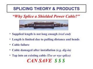
• Supplied length is not long enough (reel end)
• Length is limited due to pulling distance and bends
• Cable failure
• Cable damaged after installation (e.g. dig-in)
• Tap into an existing cable (Tee or wye splice)
CAN SAVE $ $ $
“Why Splice a Shielded Power Cable?”
2. cause serious injury or death. Installation should be performed by
personnel familiar with good safety practice in handling high
voltage electrical equipment. De-energize and ground all electrical
systems before installing product.
Caution: Working around energized high-voltage systems may
SPLICING THEORY &
PRODUCTS
3. DEFINITION
A Splice can be defined as two or more
conductors joined with a suitable
connector, reinsulated, reshielded and
rejacketed with compatible materials
applied to a properly prepared surface.
4. Functions of
MEDIUM VOLTAGE SPLICES
• Insulate Between Voltage and Ground
• Maintain Metallic Shield Continuity
• Provide Protection from Impact and Moisture
• Provide for a 30-40+ Year Service Life
• Provide Resistance to Acidic & Alkaline Soil
• Control Electrical Stress in Connector Area
5. Common Steps for
POWER CABLE SPLICING
2. Join Conductors with a Connector
3. Reinsulate
4. Reshield
5. Rejacket
1. Properly Prepare Surface
7. Common Methods of
SHIELDING THE CONNECTOR AREA
SEMI-CON “GRADING”
EXAMPLE
TAPE
SPLICE
MOLDED SPLICE
CONDUCTIVE “ELECTRODE”
CAPACITIVE (HI-K) “GRADING”
(“Faraday Cage” Effect)
HEAT SHRINK
SPLICEEXAMPLE
EXAMPLE
8. Common Methods & Materials for
RE-INSULATING
EPR
RUBBER
SPLICING
TAPE
SILICONE RUBBER
COLD SHRINK
EPDM
MOLDED
PUSH-ON
EVA
HEAT SHRINK
9. Common Methods of Semi-Con
RE-SHIELDING
INSULATION
SHIELD
HEAT SHRINK
SPLICE
TAPE SPLICE
MOLDED RUBBER SPLICE
Semi-Conducting
Tape
Integral Molded
Semi-Conducting Jacket
Semi-Conducting H.S. Tube
10. Common Methods of Metallic
RE-SHIELDING
Braided
Shielding Tape
Shielding Sleeve
(or Shielding Sock)
Concentric Neutral Wires
(from Original Cables)
Ground Strap Jumper
12. GROUNDING
• The shielded cable system must be grounded!
• There are many engineering & safety considerations
for determining where & how many times to ground.
• A splice does not necessarily have to be a grounding
location.
• Splice manufacturers generally provide a method for
grounding (for use if the splice is to be grounded).
?
16. 3M™ QS- II APPLICATIONS
JACKETED CONCENTRIC NEUTRAL CABLES
Without Splice Jacketing
Cold Shrink Jacket Heat Shrink Jacket
17. Comparison to
PUSH-ON “REPAIR SPLICE”
Standard 3M™ QS-II Splice Kit
(For repairing damaged cable with 1 elongated splice,
eliminating the need for 2 standard splices)
3M QS-II Cable Repair Splice Kit
18. + Less Installation Time than Tape Splice
+ Production Tested Splice Body
- Installation Force to Push on Splice
- Parking Position on Prepared Cable (Non-symmetrical cutbacks)
- Limited Application Range
- Special Connector Required
- EPDM - Rigid in Cold Weather
- Must Know Cable Details
PUSH-ON EPDM RUBBER SPLICE
25. HEAT SHRINK SPLICE
+ Less Installation Effort and Time than Tape Splice
+ Wide Application Range (Easy Size Transitions)
+ Symmetrical Cutbacks
- Parking Position on Cable Jacket
- Torch Required (Permit required or Torch not allowed)
- Applying Heat Properly
- Must Know Cable Details
Note: This is not a 3M product
29. Cold Shrink “EPDM RUBBER” Splice
+ Less Installation Effort
+ Wide Application Range (Easy Size Transitions)
+ Symmetrical Cutbacks
+ Constant Pressure on cables/connector
- Parking Position on Cable Jacket
- EPDM does not shrink well in Cold Weather
- Possibility for Core Hang-up
- Must Know Cable Details
Note: This is not a 3M product
30. Example of
Cold Shrink “SILICONE RUBBER” Splice
3M™ QS-III Cold Shrink Cable Splice
Installed
(With Cold Shrink Jacketing)
31. Cold Shrink Silicone Rubber Splice
INSTALLATION
Step 1 Step 1 Continued)
Step 2 Steps 3 & 4
Park Jacketing Tube(s) Park Splice Body
Connect Apply
Red Compound
32. Step 5 Step 6
Step 7 Step 8
Install Splice Body Connect Neutrals
(not shown)
(Shield Sleeve
for shielded cable
Shown)
Rubber Mastic Position
Jacketing Tube
34. + Less Installation Effort
+ Wide Application Range (Easy Size Transitions)
Cold Shrink “SILICONE RUBBER” Splice
+ Symmetrical Cutbacks
+ Constant Pressure on cables/connector
+ Silicone Material shrinks well in all weather and is flexible
+ Production Tested Splice Body
- Parking Position on Cable Jacket
- Possibility for Core Hang-up
- Must Know Cable Details
Note: This is a 3M product
36. 3M™ QS-III Cold Shrink Cable Splice
“FEATURES”
• COLD SHRINK DESIGN - Constant pressure on cables/connector
– Good seal between cable and splice
– Higher impulse Voltage levels
– Lower interface electrical stress
• SILICONE RUBBER MATERIAL
– Good cold weather application
– High temperature rating (class H)
– Flexible splice body - moves with cable
• SPECIAL ELECTRODE DESIGN - Minimizes electrical stress
– Undercut electrode end – Patented electrode places higher
stresses within splice insulation, not along cable interface
37. 3M™ QS-III Cold Shrink Cable Splice
“ADVANTAGES”
• No special tools (easier installation)
• Minimized workmanship (faster installation)
• Factory tested (reliability)
• Quick installation (lower installed cost)
• Safe (no gas, open flame, etc.)
38. 3M™ QS-III Cold Shrink Cable Splice
SUMMARY
THIS NEW GENERATION OF POLYMERIC
SPLICES TAKES ADVANTAGE OF:
• New Developments in Silicone Rubber Technology
• Integrated 1-piece Design
• Factory Made - Factory Tested, Reliability
• Cold Shrink Design for Easier Field Installation
39. SPLICING SUMMARY
• A “splice” may be considered as the reconstruction of a short
section of cable - For proper splice selection, “match the cable”!
• Good cable preparation is critical for a reliable splice installation !
• For most installations where the cable details are known, modern
molded and shrink type splices may be used for reliability,
simplicity andfast installation.
TITLE SLIDE
Unlike terminations, (which are needed to terminate the ends of every shielded cable run), splices are not necessarily required for a cable installation. Whenever possible, splicing is normally avoided. However splicing is often an economic necessity. There can be many reasons for constructing or installing a splice.
For splice selection (voltage rating, conductor size, shielding type, etc.):
“MATCH THE CABLE”
DEFINITION OF A SPLICE
In addition to this textbook definition, splices are often referred to as “rebuilding the cable,” or “building a short section of cable,” where all of the cables layered functions are reproduced using various methods and materials.
LIST OF MEDIUM VOLTAGE SPLICE FUNCTIONS
These functions provide for the electrical integrity of the cable and splice system, plus providing sealing, mechanical protection and longevity for splice field applications such as immersion in manholes, direct burial, aerial installations, etc.
LIST OF COMMON SPLICING STEPS
Emphasis is on the importance of the first step, “properly prepare surface.” Good cable preparation is critical for a quality splice installation.
All of the cable layers or functions are dealt with, starting with a connector to rebuild the cable conductor; then shielding the connector to replace the cable strand shield; insulating the connection to replace the cable insulation; shielding with semi-con and metallic layers (including a ground jumper or bonding wire) to rebuild the cable insulation shield; and finally rejacketing the splice to replace the cable jacket or sheath for moisture and mechanical protection.
COMMON SPLICING METHODS
These are basic splicing methods. In actual splice applications, technologies are often mixed to optimize a splice design. For example a molded rubber splice may use a cold shrink tube for rejacketing; or an armored cable splice may use cold shrink for phase insulation and resin for re-armoring; etc.
SHIELDING THE CONNECTOR AREA
The pictures illustrate 3 common methods of shielding the connector area (replacing the cable strand shield).
(Top) The tape splice simply uses semi-conducting tape to replace the cable semi-con layer. The smooth taping job shields the voids among the conductor strands and electrically grades the profile of the crimped connector.
(Center) The capacitive grading uses a high dielectric constant (high-K) material to distribute the electrical field and reduce the electrical stress in the connector area (capacitive stress control is explained in more detail in the “Termination Theory” presentation).
(Bottom) The conductive electrode acts as a “Faraday Cage” to smoothly distribute the electrical field over the connector area. The electrode must be in contact with the energized connector to serve this function. This places the shield around the air cavity, so that the air is not in the electrical field and therefore not electrically stressed. To accommodate this, specific connectors are usually specified for molded rubber push-on type splices.
METHODS FOR REINSULATING THE SPLICE
To perform the cable insulation function of “containing the voltage,” several different methods and materials are commonly used.
Some methods are more versatile (e.g. tape method)
Some methods allow for factory production testing to assure reliability
(e.g. molded rubber splices, per IEEE Std. 404)
Some are faster in install (e.g. cold shrink method)
Some require special tools (e.g. heat shrink method)
SEMI-CON SHIELDING
The cable semi-con insulation shield can be replaced with various methods and materials:
Semi-conducting tape should be smoothly half-lapped over the splice insulation.
Heat shrink should be evenly heated and applied smoothly. Start shrinking in center and move out towards ends to prevent trapping air (bubble).
Molded rubber splices have a built-in (integrated) semi-con jacket that is factory applied. No special installation procedures are necessary.
METALLIC SHIELDING
The metallic shielding continues the current carrying component of the cable shield across the splice. This can consist of:
Electrostatic shielding (as shown with the braided shielding tape) This is not designed to carry shield currents, and must be used in conjunction with a jumper.
Jumper or bonding conductor (as shown with the ground strap jumper and concentric neutral wires) It must have an ampacity rating equal to that of the cable shield.
Both (for example, as used in a normal tape splice construction - not shown) The shielding sleeve combines both the electrostatic and jumper functions in a single component..
NOTE: All splice designs should contain a jumper to carry any shield currents from one cable to the other. (Whether or not the splice is actually grounded at a particular location is an engineering consideration. However, the splice should provide for the possibility of such ground connection.)
RE-JACKETING
The splice jacket continues the mechanical protection and moisture barrier of the cable jacket. In some splice designs, such as molded rubber splices, the outer layer is a jacket that serves as both the protective covering and the semi-conductive component of the insulation shield system. This is known as a semi-conductive jacket.
SPLICE GROUNDING
This visual discusses splice “grounding”: Should the shielded cable system be grounded at this splice location? ...or not? If yes, the splice should provide a method for grounding the cable/splice metallic shielding to a system ground point.
Generally if no grounding specifications are available, it is common practice for a contractor to ground every splice (and termination). For splices, this is typically done in manholes, vaults, etc. When specifications are used, there may be good technical reasons for not grounding at certain locations (e.g. for single-point grounding).
For jacketed direct-burial systems (e.g. jacketed concentric neutral cables), there is a RUS (Rural Utilities Service) specification for grounding the primary neutral at least every 1329 ft. (1/4 mile). (Reference: RUS Bulletin 83-1) There are special grounding kits available to accommodate this (e.g. 3M 2252 Grounding Kit)
PUSH-ON SPLICE INSTALLATION
The photo shows a molded rubber splice (sometimes referred as a pre-molded splice) being pushed over prepared cables. The splice will be centered over the crimped connector. This type of splice usually requires a special connector, so that proper contact is made with the splice inner electrode.
CUTAWAY DRAWING OF A “MOLDED RUBBER” SPLICE
This cutaway drawing of a typical molded rubber splice reveals the integrated components of the design (electrode, insulation and jacket). Note how the semi-conductive electrode makes contact with the connector; how its ends have a radius to reduce electrical stress at the cable interface; and how the outer semi-con jacket forms a stress cone at the ends of the cable semi-con.
EXAMPLES OF PUSH-ON MOLDED SPLICES
These three splices all install and work in a similar manner.
The Cooper EZ II is the newest of them. Some installers like the unique molded shape because it is easy to grasp while pushing the splice onto the cables.
The 3M QS-II has a very good “track record,” dating back to its product release in 1980. The performance of this splice was used as an example for the development of the original IEEE 404 “production testing” (100% factory testing).
EXAMPLES OF JACKETING A JCN SPLICE
The photo shows the same type of molded push-on splice (3M 5411 QS-II) on JCN cable, with and without jacketing. Two common methods of jacketing such an application are with cold shrink (3M SJ-1A) or heat shrink (3M HSJ-1) products, as shown.
REPAIR SPLICE
The repair splice is a specially elongated molded rubber splice designed to repair damaged cable. It uses a special “long” connector to replace the damaged conductor. This splice/connector combination eliminates the need to splice in a new section of cable with two separate splices.
ADVANTAGES AND DISADVANTAGES
This visual lists the good points of a typical push-on rubber splice (red +s), and the disadvantages (blue –s).
HEAT SHRINK SPLICE INSTALLATION
The photo shows the installation of the rejacketing tube, the final layer of this heat shrink splice. Note the heat shrink torch producing the recommended “bushy” flame.
CUTAWAY DRAWING OF A HEAT SHRINK SPLICE
This cutaway drawing of a typical heat shrink splice reveals the layered components of the design. Note that instead of semi-conductive rubber, the connector and semi-con cutbacks are shielded with a stress relief material. This particular design utilizes a splice tube (co-extruded heat shrink tube) that combines the splice insulation and insulation shield functions in a single tube. Also note that a hot-melt sealant is used for the jacket sealing.
MAIN COMPONENTS OF A HEAT SHRINK SPLICE
Stress relief material
Black rejacketing tube
Black/red dual wall tube
Red insulating tube
Black stress control tube
PRIMARY INSTALLATION STEPS
For a Heat Shrink Splice
PRIMARY INSTALLATION STEPS
(Continued)
PRIMARY INSTALLATION STEPS
(Continued)
ADVANTAGES AND DISADVANTAGES
This visual lists the good points of a typical heat shrink splice (red +s), and the disadvantages (blue –s).
COLD SHRINK SPLICE INSTALLATION
Photo shows installation of the cold shrink jacket, the final layer of this splice.
CUTAWAY DRAWING OF “COLD SHRINK” MOLDED SPLICE
This cutaway drawing of a typical “cold shrink” molded rubber splice reveals the integrated components of the design (electrode, insulation and insulation shield). Note how the electrode varies from that of a molded push-on splice: The shrink characteristics of the design causes the electrode to shrink tightly against both the cable and connector, without the large air cavity of a typical push-on design. This makes the “cold shrink” design much less connector sensitive, and it can normally be used with standard compression connectors.
PIRELLI ELASPEED SPLICE
Photos show before and after installation. The jacket pull straps can be difficult to use under field conditions.
ADVANTAGES AND DISADVANTAGES
This visual lists the good points of a Cold Shrink EPDM rubber splice (red +s), and the disadvantages (blue –s).
3M QUICK SPLICE III
Photos show before and after installation. Note that both the splice and jacket are cold shrink applied (no pull tabs or pull straps are necessary).
ADVANTAGES AND DISADVANTAGES
This visual lists the good points of a Cold Shrink silicone rubber splice (red +s), and the disadvantages (blue –s).
INTRODUCTION OF THE 3M QS-III
Photos show “cold shrink” installations of both the splice body and the outer jacket.
LIST OF QS-III FEATURES
Cold Shrink Design - 3M invented “cold shrink” technology. Over 30 years of experience has resulted in numerous design improvements.
Silicone Rubber Material – As a cold shrink splice material, silicone rubber is unique to 3M. During the development stages it proved to have several key advantages over EPDM (e.g. better cold weather performance, better heat resistance qualities, better ability to maintain conductivity through stretched-to-shrunk transition, etc.)
Special Electrode Design – This patented design feature controls the stress in the critical area at the end of the splice electrode. The result is reduced electrical stress along the cable/splice interface for a more reliable splice.
LIST OF QS-III ADVANTAGES
These “advantages” can be linked to the aforementioned “features” to reveal a FAB (features, advantages, benefits) for the QS-III Splice.
SUMMARY OF QS-III
OVERALL PRESENTATION SUMMARY
REVIEW SPLICE SAMPLES
(Provided by 3M Representative)