2. cause serious injury or death. Installation should be performed by
personnel familiar with good safety practice in handling high
voltage electrical equipment. De-energize and ground all electrical
systems before installing product.
Caution: Working around energized high-voltage systems may
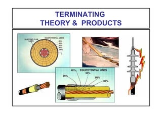
TERMINATING
THEORY & PRODUCTS
3. CLASS 1 TERMINATION
(IEEE Standard 48)
• Electric Stress Control
for the Cable Shield Terminus
• External Leakage Insulation
between H.V. Conductor and Ground
(Tracking Protection)
• A Seal
to the External Environment
11. DIELECTRIC (HIGH-K) STRESS CONTROL
High-K (high dielectric constant) material is used
to reduce stress at the shield discontinuity by
field refraction due to different K values of
two adjacent dielectric layers.
17. II. EXTERNAL LEAKAGE INSULATION
Between Conductor & Ground
THE
INSULATOR
FLASHOVER PROTECTION TRACKING PROTECTION
BIL per (IEEE 48)
18. TRACKING
• MOISTURE
- Humidity
- Fog
- Condensation
- Mist
- Snow
- Rain
• CONTAMINATION
- Dust
- Chemicals
- Salt
- Other Airborne Particles
• VOLTAGE
- Surface Stress (V/mil)
Three Conditions Must Exist:
19. DISCHARGE
FORMATION Surface Resistance
Reduced When Wet
DRY BANDS
ELECTRICAL
DISCHARGES
(Generated in
Dry Band Areas)
(Areas of Higher
Surface Resistance)
&
Concentrated
Voltage Gradient
20. Ways To
CONTROL TRACKING
3. Track Resistant Materials
- Porcelain
- Silicone Rubber
- Inorganic Fillers in EVA (Heat Shrink)
- Inorganic Fillers in Rubber
2. Rain Shed (Insulator Skirts)
1. Increase Distance from HV to Ground
21. Advantages of Silicone Rubber as
INSULATOR MATERIAL
4. Silicone is Mostly Inorganic --
(No Conducting Carbon Path)
3. Silicone is Inherently UV-Stable
2. Silicone Can Recover Its Hydrophobicity
1. Silicone is Hydrophobic
5. Silicone Has a Smooth Surface
24. Recovery of Contact Angle for
SILICONE RUBBER TERMINATIONS
Recovery of Contact Angle
24 Hrs. (Recovered)
90 Deg. Recovery
(Based on study performed in
cooperation with Arizona State University)
27. SUMMARY and CONCLUSIONS
• Silicone Insulators are superior to EPDM, EVA and
porcelain insulators
• Silicone is more hydrophobic than other polymers or
porcelain
• Silicone has the ability to regenerate its hydrophobicity
in the event that high-leakage current changes its state
• Silicone Insulators are inherently stable to UV due to
its high backbone bond energy
• 3M™ Silicone Rubber Terminations - In use 30+ years
with excellent results
28. III. SEAL
To the External Environment
Top Seal
Bottom Seal
Potting
Compound(Conductor Seal)
(Jacket Seal)
40. Examples of Silicone Rubber
COLD SHRINK TERMINATIONS
Joslyn JPT &
Plymouth/Bishop ColdTerm
3M™ QT-II Termination 3M™ QT-III Termination
Plymouth Joslyn
Silicone
Tape
Top Seal
Silicone
Tape
Top Seal
Pull Tabs
Integrated 1-Piece
Silicone
Grease
Silicone
Grease
41. Examples of Silicone Rubber
COLD APPLIED (Shrink) TERMINATIONS
Raychem TFT
Twist & slide off of
holdout tube onto cable
“Holdout” Tube
Adjust into final
position if necessary
Use pull tabs to
position over jacket
VITAL STEP: Loosen
termination by twisting
until it moves on holdout
42. Typical Cold Shrink Termination
INSTALLATION
Apply mastic
seal around jacket
& neutral wires
Apply silicone
grease to fill
semi-con step
45. BENEFITS of COLD SHRINK
• Environmentally Stable Materials
• Broad Application Range
• Live Seal
• Good Interfacial Pressure
• Low Installation Force
• No Tools for Installation
49. SIZE COMPARISON: 15 KV CLASS
- Shorter cable
prep distance
- Accommodates
smaller space in
cabinets
- More versatile for
mounting
3M ™ QT- II
Termination
3M ™ QT- III
Termination
50. INVERTED
3M™ QT-III Outdoor Termination
• SILICONE SEALING COMPOUND
No (inverted) bottom seal taping required
Eliminates silicone grease at
semi-con cut-back step
• HI-K SEALING COMPOUND
BUILT-IN COMPOUNDS:
51. SUMMARY
“TECHNOLOGY AND THE HUMAN FACTOR”
• Cold Shrink Design for Easier Field Installation
• Factory Assembled Quality - Reliability
• Integrated 1-piece Designs
• New Developments in Sealing Compounds
• New Developments in Silicone Rubber Technology
This New Generation of Polymeric Terminations
Takes Advantage of:
TITLE SLIDE
This presentation will discuss and review the basic theory and functions of medium voltage cable terminations, and the common termination products in use.
IEEE CLASS 1 TERMINATION
This slide summarizes the 3 main functions of the termination.
Electric stress control for the cable shield terminus.
External leakage insulation between the high voltage conductor and
ground.
A seal to the external environment, and to maintain the pressure,
if any, within the cable system.
The other 2 termination classifications are:
IEEE Class 2 - Stress control and insulator functions only (this termination
class is not in common use)
IEEE Class 3 - Stress control function only (for a clean, protected
environment)
I. STRESS CONTROL
This visual introduces the primary function of a termination.
The illustration shows the cable shield terminus (the end of the cable semi-conducting layer). This is the cable area that requires electric stress control.
ELECTRIC FLUX
This illustration is a review of cable theory - it shows the even radial
distribution of the electric field within a shielded power cable.
In a continuous shielded cable the electric field is uniform along the cable axis and there is variation in the field only in a radial section. Because of the 2 semi-conducting shields shown (the strand shield and the insulation shield), the shortest path to ground for the electric flux is equal around the entire radial section.
EQUIPOTENTIAL LINES
This illustration is a field plot of the electric field in a shielded cable, showing the higher electrical stress level at the conductor.
A common method for mapping the electric field is called “field plotting,” where equipotential lines are generated to show the percentage of voltage drop throughout an insulation system. Computer software is the usual method used today. These equipotential lines intersect the flux lines at 90 degrees.
The spacing of the electric flux lines and the corresponding equipotential lines is closer in the vicinity of the conductor than at the shield, indicating a higher electric stress in the insulation at the conductor. This stress increase, or concentration, is a direct result of the geometry of the conductor and shield in the cable section. The stress is accommodated in practical cables by insulation thicknesses sufficient to keep the stresses to acceptable levels.
PREPARED CABLE - WITHOUT STRESS CONTROL
In terminating a shielded cable it is necessary to remove the shield
to a point some distance from the exposed conductor.
This is to secure a sufficient length of insulation surface to prevent breakdown along the interface between the cable insulation and the termination insulator. The actual length required is determined by the operating voltage, the properties of the insulating materials and the design of the termination.
FIELD PLOT – NO STRESS CONTROL
It reveals a high electric stress concentration at the edge of the shield.
(Note that the 20% equipotential line is almost touching the cut-back edge of the shielding, indicating a high electrical stress level.)
The removal of the insulation shielding results in a discontinuity in the axial geometry of the cable. The electric field is no longer uniform axially along the cable, and exhibits variations in three dimensions.
The illustration shows the electric flux originating along the conductor and converging on the end of the shield. The close spacing of the equipotential lines at the shield signifies the presence of high electrical stresses in this area. Because of the shield removal, these stresses are concentrated in the air surrounding the cable. The dielectric strength of the air (nominally about 76 Volts/mil) is much less than that of the cable insulation (about 800 Volts/mil). Cable failure can occur from the air electrically breaking down (corona discharges) and eroding the cable insulation.
Steps must be taken to reduce the stresses occurring near the end of the shield if cable insulation failure is to be avoided. This is called stress control.
GEOMETRIC STRESS CONTROL
This illustration shows a stress cone installed.
(The “black” is a conductive shield layer, and the “gray” is insulation.)
All terminations must at least provide stress control. This stress control may be accomplished by 2 commonly used methods, geometric or capacitive. The illustration shows a traditional geometric “stress cone.”
A stress cone involves an extension of the shielding which expands the diameter at which the shield discontinuity occurs, thereby reducing the stress at the discontinuity. The thickness of the insulation under the shield discontinuity is also increased, further distributing the electric field and reducing the electrical stress.
FIELD PLOT – STRESS CONE
This illustration is a field plot of a shielded cable
with a geometric stress cone installed.
Note that the 20% equipotential line has been moved away from the shield, resulting in a much lower electrical stress level at the stress cone shield terminus.
(On a 15 kV cable, this 3M stress cone would reduce the stress at the edge of the semi-con to approximately 20 volts/mil. This compares to approximately 100 volts/mil before the stress cone was installed. Remember that air breaks down at approximately 76 volts/mil.)
CAPACITIVE STRESS CONTROL
Definition of “dielectric” or “high-k” stress control
DIELECTRIC CONSTANTS
Note that the Hi-K material has a K value that is an order of magnitude greater than the cable insulation or 130C insulating tape.
(The K values for the 3 materials listed are for demonstration only, and do not represent the exact values for specific materials.)
Definition: Dielectric Constant (or Permittivity) - is the ratio of the capacitance of a material to that of a vacuum (air for practical purposes). Therefore air has a K of 1.
Although the Hi-K material has a higher K value, it maintains the dielectric strength properties of an insulator (it is an insulation, not a semi-conductor).
CAPACITIVE STRESS CONTROL
The Hi-K material (K30) is applied onto the cable insulation (K3)
so that it overlaps the end of the shield cut-back.
EXAMPLE OF REFRACTION
The principles of Hi-K stress control are based on laws of refraction.
“Snell’s Law,” which explains the refraction of light, (as illustrated by the pencil passing from air to water, where the light passing obliquely is bent or refracted at the interface of the 2 mediums).
FIELD PLOT – CAPACITIVE STRESS CONTROL
This illustration is a field plot of a shielded cable with hi-k stress control.
Note how the 20% line is spaced away from the cable shield terminus, and note the even distribution of the equipotential lines along the cable/stress control interface. (On a 15 kV cable, the QT-II reduces the stress to approximately 9 volts/mil, while the QT-III reduces it to less than 7 volts/mil.)
“Maxwell’s Law,” explains that the electrical flux (electrical field) is refracted at the dielectric interface (The electrical flux passing obliquely through the cable/stress control interface is refracted into the hi-k material.), similar to the way light was refracted per Snell’s law.
The hi-k stress control material capacitively changes the voltage distribution in the electrical field surrounding the cable shield terminus. The electrical flux is regulated to equalize the electrical stresses in a controlled manner along the entire area where the shielding has been removed.
By changing the electrical field surrounding the termination, the stress concentration is reduced from several hundred volts per mil to values found in the continuous cable - usually less than 50 volts/mil at rated voltage.
FIELD PLOT COMPARISON
This composite illustration is a comparison between the field plots of a traditional stress cone termination and a high-k stress control termination.
(Note the higher stress concentration and longer length of the stress cone termination)
Traditional Stress Cone Termination - Although the electrical stress is reduced at the shield terminus, most of the electric field (90% in the example) is distributed along the length of the stress cone. The skirted insulator only protects a small portion of the field (10% in the example) along the rest of the termination. To compensate for this disproportional field distribution (to attain some degree of tracking protection), traditional terminations were made notably longer than the current high-k designs.
High-K Stress Control - Note how this termination integrates the stress control and insulator functions, resulting in a shorter termination. The high-k stress control evenly distributes the electric field along the entire surface of the skirted insulator. This can be seen by tracing the insulator surface along the length (creepage distance) of the example, where there is no concentration of the electric field.
II. INSULATOR FUNCTION
This visual introduces the second function of an IEEE Class 1 (or Class 2) Termination:
External leakage insulation between H.V. conductor and ground
(protection from flashover damage and from tracking damage).
Terminations can be subjected to flashovers such as lightning induced surges or switching surges. A termination must be designed to survive such surges. They are assigned a BIL (basic lightning impulse insulation level or just basic impulse level) according to the insulation class (per IEEE Std. 48). As an example, a 15 kV class termination has a BIL rating of 110 kV-crest.
Terminations are also subjected to tracking. Tracking can be defined as the process that produces localized deterioration on the surface of the insulator, resulting in the loss of the insulating function by the formation of a conductive path on the surface.
TRACKING
List of the 3 conditions necessary for tracking.
Moisture conditions of high humidity, fog and condensation are worse than simple snow or rain. Conditions like rain can clean the insulator surface of contaminate and create a leakage path that is external to the termination surface.
An energized termination has an applied voltage, of course. However the termination design can have a notable influence on the insulators surface stress distribution. The aforementioned hi-k stress control can evenly distribute the surface stress, allowing for a physically short termination design with high electrical performance.
ILLUSTRATION OF TRACKING
This illustration is shown to explain how dry bands are formed, how these dry regions concentrate the electrical stresses and how these stresses generate electrical discharges in the form of “tracking.”
METHODS FOR CONTROLLING TRACKING
Common methods of protecting against tracking damage.
The remainder of the presentation will focus on the superior qualities of silicone rubber as a material resistant to tracking damage.
The photo illustrates the creepage distance (or leakage distance) for 2 types of silicone rubber insulated terminations. (Note how the convoluted skirted surface of the left termination allows the overall height of the termination to be much shorter. The undercut skirts also disrupt any wet leakage paths that occur in various outdoor or industrial environments.)
The straight, tape termination (on the right side of the photo) would normally be considered as a indoor termination due to its lack of insulator skirts.
SILICONE RUBBER INSULATOR
A list of general properties of “silicone rubber”
These are properties that make silicone rubber a superior material for use as a termination insulator.
HYDROPHOBICITY VS. HYDROPHILICITY
Actual examples of “Hydrophobicity” and “Hydrophilicity”
A drop of water was applied to both insulators:
Note how the water “balls-up” on the silicone rubber insulator. This is called “hydrophobic,” where the insulator tends to be self-cleaning. The results are a dryer surface which maintains a higher surface resistance and lower leakage currents. (Analogies: “Like water off a duck’s back” or “…a freshly waxed car”)
Note how the water spreads-out on the porcelain insulator. This is called “hydrophilic,” where the insulator surface “wets” out. The results are a wet surface with lower surface resistance and higher leakage currents. Heat shrink and EPDM insulators react this way, especially after they have been in service for a while.
CONTACT ANGLE
The illustration shows how the “contact angle” is measured.
An obtuse contact angle (greater than 90 degrees) is generally considered “hydrophobic,” while an acute contact angle (less than 90 degrees) is considered as “hydrophilic.”
Note that the energy from high leakage currents can cause a hydrophobic insulator surface to change and become hydrophilic. Silicone rubber has a unique property which allows it to recover from this phenomenon and return to its original hydrophobic state.
CONTACT ANGLE RECOVERY
Plot of Contact Angle Recovery for Silicone Rubber
Note how recovery of the contact angle (90 degrees) was made in about 24 hrs.
This plot is from a cooperative study by 3M and Arizona State University titled “Contamination Performance of Silicone Rubber Cable Terminations.” (Ref.: IEEE paper 90 WM 074-5 PWRD, 1989)
Although being changed from hydrophobic to hydrophilic, the silicone rubber insulator still contains oligomers (low molecular weight fraction of the silicone) which remain free within the silicone rubber. Only the insulator surface has been altered by the high leakage currents. Removal or reduction of one or more of the tracking conditions (contamination, moisture or voltage) allows the oligomers to migrate back to the surface of the insulator, reestablishing an equilibrium and restoring the hydrophobicity. A common example of recovery conditions would be the clearing of weather. (Studies have suggested that the insulator will maintain this recovery capability for well beyond a normal life cycle.)
CONTAMINATION VS. HYDROPHOBICITY
Photo shows the “Hydrophobic” state of a
heavily contaminated silicone rubber insulator
A coating of this same contaminate on a porcelain, heat shrink or EPR surface soaks up water and becomes very “hydrophilic.” However, the chemical make-up of the silicone rubber allows an insulator to maintain its hydrophobicity, even when coated with contamination. Similar to the previously mentioned process of restoring the surface hydrophobicity, the oligomers remain free within the silicone rubber and migrate to the surface of the contaminate, thus maintaining the insulator hydrophobicity.
This unique property minimizes the need to clean insulators, and also eliminates the need to periodically coat them with a sacrificial silicone coating.
SUNLIGHT DAMAGE
Photograph showing a UV damaged EPDM insulator
The altered surface condition and numerous cracks can trap water and contamination, thus promoting tracking conditions. Other carbon based materials (e.g. heat shrink) can be similarly damaged by exposure to sunlight.
The molecular bond strength of silicone rubber (445 kilo-Joules/Mole) is greater than the UV energy available in normal sunlight (398 kilo-Joules/Mole). Therefore silicone rubber is highly resistant to this kind of damage.
SILICONE RUBBER SUMMARY
III. SEALING FUNCTION
This visual introduces the third function of an IEEE Class 1 Termination
A SEAL to the external environment, at both the conductor (lug) and jacket (and ground).
TAPE SEAL
Example of a tape termination
(silicone tape being applied for tracking protection)
POTTING SEAL
Example of a porcelain termination
(filling with a potting compound)
HEAT SHRINK SEAL
Example of a heat shrink application
(Torch and source of fuel required for”bushy” flame)
COLD SHRINK SEAL
Example of a Cold Shrink Application
(Live rubber forms a seal to the cable surface)
TERMINATION TYPE – HEAT SHRINK
(Note “bushy” flame being applied to shrink termination)
HEAT SHRINK TERMINATION KIT
Primary components of a Heat Shrink Termination
Along with a Completed termination
Red, non-tracking tube
Black, stress control tube
Red, mastic strips
Red, heat-shrinkable skirts
Yellow, angle-cut mastic strip
PRIMARY INSTALLATION STEPS
Primary installation steps for a heat shrink termination
PRIMARY INSTALLATION STEPS
(continued)
PRIMARY INSTALLATION STEPS
(continued)
PRIMARY INSTALLATION STEPS
(continued)
TERMINATION TYPE – COLD SHRINK
EXAMPLES
Silicone Rubber Cold Shrink Terminations
Joslyn JPT and Plymouth/Bishop ColdTerm™ - These are apparently manufactured by the same company (Joslyn). Note that the Plymouth is colored a standard Munsel Grey (sky blue), while the Joslyn is Dark Gray. The “Pull Tabs” can be quite difficult to manipulate in field conditions, and they are a required additional installation step.
3M QT-II – This is a second generation 3M Cold Shrink design. It is colored Munsel Grey. Note that it contains a built-in jacket cover (step core) that eliminates the extra step of using pull tabs.
3M QT-III – This is the latest 3M Cold Shrink Termination. It is colored dark gray to differentiate it from the previous model. Note that it is an integrated 1-piece design that eliminates the extra steps that are required for the other terminations. Also notice that it is notably smaller in size, for less space on poles or in enclosures, and requires less cable preparation length.
EXAMPLES
Cold Applied Terminations
Raychem TFT Termination – This is another example of a Cold Shrink Termination. Instead of using a spiraled core like the preceding examples, it contains a “holdout” tube. This tube must first be loosened by twisting of the termination until the entire termination is loose on the holdout. Care must be taken with this extra step to prevent the tube from prematurely sliding off the end of the holdout tube. After sliding the termination onto the cable, it must be inspected for proper positioning. If not correct, the termination must be re-positioned as shown in the instructions.
The TFT Terminations requires the use of pull tabs to cover the cable jacket. This additional step can be a quite difficult in field conditions.
PRODUCT INTRODUCTION
3M Quick Term III Termination (QT-III)
IMPROVEMENTS – QT-II VS. QT-III
Improvements made for Quick Term III
These are notable improvements in the materials, sealing, and stress control. The results are a smaller, easier to install, higher performance termination.
QUICK TERM III COMPONENTS
(1-piece construction)
QTII - QTIII SIZE COMPARISON
(Examples are for 15 kV distribution class installations)
INVERTED APPLICATIONS
Quick Term III Kits are available specifically for inverted applications
(These kits have all of the features of standard QTIII Kits)
SUMMARY OF QUICK TERM III FEATURES
REVIEW SPLICE SAMPLES
(Provided by 3M Representative)