1. 3.4 VOLUME DAMPER KIT
3.4
REGULATION OF AIR FLOW
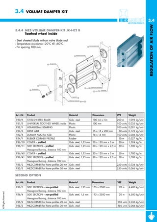
3.4.4 MEZ-VOLUME DAMPER-KIT JK-I-02 B
Toothed wheel inside
- Steel sheeted blade without valve blade seal
- Temperature resistance: -20°C till +80°C
- Fin spacing 100 mm
Art.-Nr. Product Material Dimensions VPE Weight
930/6 STEEL-SHEETED BLADE Galv. steel 100 mm x 5m 200 m 1,093 kg/unit
931/5 UNIVERSAL TOOTHED WHEEL inside Plastic 100 mm 100 units 0,035 kg/unit
932/1 HEXAGONAL BEARING Plastic 100 units 0,001 kg/unit
933/3 DRIVE AXLE Galv. steel 15 x 15 x 200 mm 50 units 0,122 kg/unit
933/4 DUMMY PLUG for Axle Plastic 15 x 15 mm 100 units 0,006 kg/unit
934/1 RUBBER CORNER PROFILE Rubber 10 m 0,027 kg/m
936/10 COVER – profiled Galv. steel, 1,25 mm 20 x 120 mm x 5 m 50 m 1,594 kg/m
936/11 SIDE SECTION – profiled Galv. steel, 1,25 mm 20 x 120 mm x 2,5 m 50 m 1,500 kg/m
Hexagonal boring, distance 100 mm
936/40 COVER – profiled Galv. steel, 1,25 mm 30 x 120 mm x 5 m 50 m 1,780 kg/m
936/41 SIDE SECTION – profiled Galv. steel, 1,25 mm 30 x 120 mm x 2,5 m 50 m 1,700 kg/m
Hexagonal boring, distance 100 mm
935/2 MEZ-CORNER for frame profiles 20 mm Galv. steel 250 units 0,036 kg/unit
935/3 MEZ-CORNER for frame profiles 30 mm Galv. steel 250 units 0,066 kg/unit
SECOND OPTION
Art.-Nr. Product Material Dimensions VPE Weight
936/1 SIDE SECTION – non-profiled Galv. steel, 1,25 mm 175 x 2500 mm 020 m 4,400 kg/unit
Hexagonal boring, distance 100 mm
All Rights Reserved
936/4 SIDE SECTION – non-profiled Galv. steel, 1,5 mm 192 x 2500 mm 020 m 6,500 kg/unit
Hexagonal boring, distance 100 mm
935/2 MEZ-CORNER for frame profiles 20 mm Galv. steel 250 units 0,036 kg/unit
935/3 MEZ-CORNER for frame profiles 30 mm Galv. steel 250 units 0,066 kg/unit
2. 3.4 VOLUME DAMPER KIT
3.4
REGULATION OF AIR FLOW
3.4.4 MEZ-VOLUME DAMPER-KIT JK-I-02 B
Toothed wheel inside
Workmanship Guidelines:
Toothed wheels:
- Toothed wheels need to be affixed on both sides
Actuator:
lichte Höhe
- Starting from a height of 1200 mm – a connecting 90
hight
rod needs to be installed
- The drive axle is to be bolted onto the blade
using a self-drilling screw or rivet
Blade layout:
Clear width minus 18 mm
width
lichte Breite
Overall dimensions:
The maximum breadth needed for the overall dimensions
1 C - P rofil
can be taken from the diagram below
6
30
120
maximale Klappenbreite blade
max. breadth of valve in Abhängigkeit von ∆P
2000 6
1750
20
Druckdifferenz [Pa]
1500
Pressure loss (Pa)
120
1250
1000
750
500
250
120
0 200 400 600 800 1000 1200 1400 1600 1800 2000
Jalousieklappenbreite
valve blade dimension
Pressure loss Motor
Druckverlustkennlinie (in geöffnetem Zustand)
Pressure loss (open valves) Stellkraftdiagramm /
Motordrehmoment
H (m) 1,5
°
300
Klappenöffnungswinkel °
45
Pressure loss [Pa]
Angle of blade
Druckverlust
1,0
200
60° 15 Nm
100 0,5
90°
8 Nm
1 2 3 4 5 0 1,5
0,5 1,0
W[m/s] B (m)
All Rights Reserved
1

![3.4 VOLUME DAMPER KIT
3.4
REGULATION OF AIR FLOW
3.4.4 MEZ-VOLUME DAMPER-KIT JK-I-02 B
Toothed wheel inside
Workmanship Guidelines:
Toothed wheels:
- Toothed wheels need to be affixed on both sides
Actuator:
lichte Höhe
- Starting from a height of 1200 mm – a connecting 90
hight
rod needs to be installed
- The drive axle is to be bolted onto the blade
using a self-drilling screw or rivet
Blade layout:
Clear width minus 18 mm
width
lichte Breite
Overall dimensions:
The maximum breadth needed for the overall dimensions
1 C - P rofil
can be taken from the diagram below
6
30
120
maximale Klappenbreite blade
max. breadth of valve in Abhängigkeit von ∆P
2000 6
1750
20
Druckdifferenz [Pa]
1500
Pressure loss (Pa)
120
1250
1000
750
500
250
120
0 200 400 600 800 1000 1200 1400 1600 1800 2000
Jalousieklappenbreite
valve blade dimension
Pressure loss Motor
Druckverlustkennlinie (in geöffnetem Zustand)
Pressure loss (open valves) Stellkraftdiagramm /
Motordrehmoment
H (m) 1,5
°
300
Klappenöffnungswinkel °
45
Pressure loss [Pa]
Angle of blade
Druckverlust
1,0
200
60° 15 Nm
100 0,5
90°
8 Nm
1 2 3 4 5 0 1,5
0,5 1,0
W[m/s] B (m)
All Rights Reserved
1](data:image/gif;base64,R0lGODlhAQABAIAAAAAAAP///yH5BAEAAAAALAAAAAABAAEAAAIBRAA7)