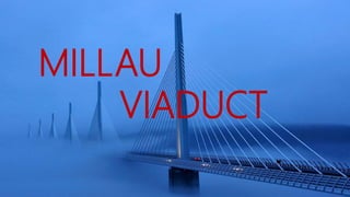
Millau via duct presentation full analysis
•Download as PPTX, PDF•
0 likes•123 views

complete case study of the structure components of the millau via duct and its design concept

Recommended
More Related Content
What's hot
What's hot (20)
Similar to Millau via duct presentation full analysis
Similar to Millau via duct presentation full analysis (20)
Recently uploaded
Recently uploaded (20)
Millau via duct presentation full analysis
- 2. MILLAU VIADUCT • The Millau Viaduct is in southern France and crosses the River Tarn in the Massif Central mountains. • It was designed by the British architect Lord Foster and at 300m (984 feet) it is the highest road bridge in the world, weighing 36,000 tonnes. • The central pillar is higher than the famous French icon, the Eiffel Tower. • The Bridge opened in December 2004 and is possibly one of the most breath taking bridges ever built.
- 3. • The bridge towers above the Tarn Valley and the aim of Lord Foster was to design a bridge with the ‘delicacy of a butter fly’. • Lord Foster designed a bridge that enhances the natural beauty of the valley, with the environment dominating the scene rather than the bridge. • The bridge appears to float on the clouds despite the fact that it has seven pillars and a roadway of 1½ miles in length.
- 4. CONSTRUCTION OF MILLAU VIADUCT
- 5. Steel deck with multiple sub-bended spans. Steel deck with continuous spans of constant depth. Steel or concrete deck with multiple cables-stayed spans Concrete bridge including an arch with an opening 600m wide over the River Tarn Viaduct with continuous spans of variable depth in concrete or composite material
- 6. 7 piers P1 to P7 2 abutments C0 & C8 6 spans 342 m long 2 side -spans 204 m long
- 7. 6 STAGES OF CONSTRUCTION 1. Raising the piers 2. Throwing the deck 3. Joining the deck 4. Installing the pylons 5. The stays 6. Finishings
- 9. Piers - The piers are the towering part of the structure with the tallest one reaching over 245 meters tall. The piers hold the road way and the pylons. 1. The piers were constructed using reinforced concrete. The piers have the design of tapering down from top to bottom. The seven piers are identical except for the length due to the valley bottom. 2. The piers have been constructed using an automatic rail climbing system or ACS. The system required the bottom section the pier be constructed then the climbing system attached to rail secured to the pier. Allowing the system to move up the piers independently . 3. The ACS would pour 4 meter sections of concrete at a time allowing accurate pours and ensuring structural stability. 4. The ACS enabled the piers to be built on schedule. The system allowed for a correct pour each time it moved up the pier.
- 10. The pier design : flexible piers at their base =strong distortion of the deck Pier design : piers with flexural rigidity at their base=Less distortion of the deck Pier Design
- 12. Usage of Temporary Piers
- 14. • THEY OPTED FOR STEEL DECK OVER THE CONVENTIONAL CONCRETE BLOCK,AS IT IS NOT ECONOMICALAND SAFE TO LIFT CONCRETE OVER SUCH HEIGHTS. FABRICATION OF THE DECK SECTION WAS DONE ON STEEL FACTORY . AROUND 2200 SECTIONS EACH WEIGHING UPTO 90 TONNES AND WERE SOME WERE 22 LONG. Steel Decks
- 15. 7 temporary piers help support the weight of the deck,as the longest deck could support was half the span. Two deck segments were launched from each end of the bridge Launching the deck
- 16. •Computerized launchers push the pre-fabricated deck segments on to the piers. •Each cycle moves the deck 600 mm. • Total of 5000 cycles required. •The cycle is repeated every 4 minutes Hydraulic launchers
- 17. •Weight of steel box girder deck sags as span is completed. •Nose recovery system attached to raise the deck to the level of the next pier. •This aligns the deck for the level and curvature of the next pier. •The precision carried out in the nose recovery system was due to the use of GPS system as the accuracy was upto 4mm. NOSE RECOVERY
- 18. Moving the deck could be accomplished three ways: manual, semi-automatic and automatic. Manual mode was used for adjustments and any necessary instant corrections. In the semi-automatic mode, each movement was made step by step, or, in other words, raise, push, lower, and then withdraw. Automatic mode completed each entire launch cycle.
- 19. In all, 18 launches — six from the north side of the bridge and 12 from the south — were required to position the deck, with the last launch accomplished on May 28, 2004.
- 21. Each pylon of the viaduct is equipped with a monoaxial layer of eleven pairs of stays laid face to face. Depending on their length, the stays were made of 55 to 91 high tensile steel cables, or strands, themselves formed of seven strands of steel Each strand has triple protection against corrosion and the stay-cables weight about 1,500 tons The exterior envelope of the stays is itself coated along its entire length with a double helical weatherstrip. The idea is to avoid running water which, in high winds, could cause vibration in the stays and compromise the stability of the viaduct. The stays were installed using a well-tried technique. After threading one strand in the outer protective sheath, it is pulled up on to the pylon to its final location. The strand is then fixed in the upper and lower anchorage points. A 'shuttle' then brings the other strands one by one, and they are then stretched to tension."
- 22. • MAJOR MATERIALS : • 1. STEEL : • Steel is used in many places where concrete was earlier used • The cost of steel and concrete was about 390 million euros (520 million dollars). • The project required about 19,000 metric tons of steel for the reinforced concrete, and 5,000 metric tons of pre-stressed steel for the cables and shrouds. • The bridge is constructed out of 2,078 steel pieces made by the EIFFEL Company, the successor of the company that built the Eiffel Tower • The deck and pylons are made of steel sheets of grade S355 and S460.
- 23. • 2. CONCRETE : • The project required about 127,000 m³ of concrete. • The concrete of the abutments and piles amounted to 85 000 m3, 40 times the Eiffel Tower • The massive piers are made from type B60 concrete, a high-strength concrete with durability characteristics more than its mechanical resistance. • During construction of the bridge concrete pours were made 4m tall
- 24. • 3. Stay Cable material : • The stay cables are made from T15 strands of class 1,860MPa which are super- galvanized, sheathed, and waxed. • The cables are protected by a white, aerodynamic sheath made from non- injected PEHD (high-density polyethylene) • Developed by through a collaboration between Buonomo, Servant, Virlogeux, Cremer, Goyet and Del Forno •
- 25. • ENVIRONMENT FRIENDLY USE OF MATERIALS • Steel was used in most places instead of concrete which reduced the use of trucks. • Included a system for collecting and processing rainwater and other waste which would be accumulated during road washing • Excess construction materials were carefully stored to use them for other operations • - wood was sent to paper mills • - oil and lubricants were sent for recycling • Various sites of production zones had been selected with an intention to keep hedge and bush felling to the minimum
- 26. PROBLEMS ENCOUNTERED • CONSTRUCTION • MAJOR CHALLENGES: 1. Build the tallest bridge piers in the world. 2. Put a 36000 ton free way on top of them. 3. Erect 7 steel pylons each weights 700 tons. 4. Land
- 27. • There are 7 piers that are numbered from the northern end of the valley. Number 1 was to cause problems because of steep slope. Number 2 was the tallest across the river number 3 was not much shorter from no. 2. Then 4, 5, 6 and 7 found the genital slope to the south. • 16000 tons of steel bars are used. The shape of each pair is complicated as a result each time they removed the section of red steel sheltering they have to change the shape of the mold to fit the profile of the next 4 meter section man handling these steel panels way up to 15 tons of piece is no picnic. And with the combine height of 7 piers totaling well over a kilometer they had to change the shape of the mold over 250 times. • Every 3 days each team on each pair went through this whole cycle then they repeated the process but it was time consuming.Month after month the piers climbed higher finally by November 2003 they reached their full height. At 245 meters pair 2 becomes the highest bridge pier in the world. The piers were exactly on the location where it had to be with 2cm deviation. 1. PIERS
- 28. 2. FREE WAY ON TOP OF THEM. • Second problem was putting a 36000 ton free way on top of the piers. Working at these heights could be lethal. Around 235 people died in the process. • Therefore the team decided to fabricate the entire rope deck on the safety of solid grounds instead of concrete, steel was used for the deck which in theory would be much safer then lifting concrete sections hundreds of meters in the position. EIFFEL, the steel firm took up the challenge. • This involved manufacturing 2200 separate sections weighing up to 90 tons and some of them 22 meters long. Their accuracy was measured with laser to within a fraction of a millimeter. The triangular side panel were welded on either side to create width for a 4 lane high way. They automated the manufacturing with a two headed welding robot and a plasma cutting machine each cutting pattern or template was programmed in to the computer then the machine automatically blazes its way through the steel.
- 29. • Another problem faced with construction was the need to eliminate error in position. • The pylons were of such enormous heights that being off even the slightest at the bottom of the pylon could spell disaster at the top of the pylon in the form of meters off the intended mark. • When considering the pylons, other challenges faced included: pouring the cement in a timely manner as to prevent from setting, hurricane grade winds faced by workers, and the intricate design of each pylon moving to the overall construction of the bridge. • This made constructing the platform a challenge all its own. Spans of this great length in the past have spelled disaster in the form of collapse of the structure and death of workers. • The road spans also would be at the highest point putting the winds at even larger velocities. Placing the 700 ton pylons atop the bridge and adding even more weight to the roadways also served as challenges that could result in the destruction and abrupt end of the Millau Viaduct. 3. Erect the steel pylons
- 30. 4. LAND • Another challenge to overcome was the need to drill and bury the foundations of the massive pylons deep into the bed rock. • The challenge here was that there are cavities throughout the country side that have fractured the limestone. These cavities are necessary to the survival of the local cheese industry. This terrain is responsible for containing the bacteria responsible for the blue mold necessary to make Roquefort cheese. • The cracked limestone meant one thing, landslides! Not far into the project this problem became a reality, with a landslide pushing rock and dirt into the first pylon. This landslide however, did not hurt the pylon.
- 32. FINISHINGS The surface (the covering of the road) of the millau viaduct is the result of several months of research. It was designed to withstand any distortion of deck & provide the necessary qualities for comfortable motorway driving. It took less than four days work to lay it. Final finishing touches: electric lighting, signposts, operating systems, final road covering.
- 33. THANK YOU! • MD MEHRAJ ALI • 12 CEB 421 • A3CB-01 • GE0096