
Recommended
More Related Content
What's hot
What's hot (19)
Viewers also liked
Similar to 05 chapt 5 pd section 5.5 process eng final_oct 04
Similar to 05 chapt 5 pd section 5.5 process eng final_oct 04 (20)
Recently uploaded
Recently uploaded (20)
05 chapt 5 pd section 5.5 process eng final_oct 04
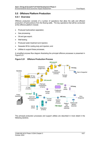
- 1. Azeri, Chirag & Gunashli Full Field Development Phase 3 Environmental & Socio-economic Impact Assessment Final Report 5.5 Offshore Platform Production 5.5.1 Overview Offshore production consists of a number of operations that allow the safe and efficient production of hydrocarbons from the flowing wells. The key operations that will be conducted at the offshore platform include: Produced hydrocarbon separation;• • • • • • • Gas processing; Oil and gas export; Well testing; Produced water treatment and injection; Seawater lift for cooling duty and injection; and Utilities to support these processes. A simplified process flow diagram illustrating the principal offshore processes is presented in Figure 5.21. Figure 5.21 Offshore Production Process HP Sep (2 trains) LP Sep (2 trains) Dehydration (single train) Flash gas Compression (2 trains) Manifolds Deaeration (2 trains) Booster pumps Sand and Hydrocyclones (2 trains) Platform well Injection downhole Gas to Sangachal Export Compression (2 trains) Power Generation Subsea well injection downhole 29 barg 12 barg 110 barg 135 barg 480 barg 1 bara SW lift pumps Fuel gas Lift gas Injection pumps (3 trains) Coalescers (2 trains) Oil to Sangachal MOL pumps Booster pumps 225 mmscfd 350 mmscfd 316 mbpd 131 mbpd 750 mbpd HP Sep (2 trains) LP Sep (2 trains) Dehydration (single train) Flash gas Compression (2 trains) Manifolds Deaeration (2 trains) Booster pumps Sand and Hydrocyclones (2 trains) Platform well Injection downhole Gas to Sangachal Export Compression (2 trains) Power Generation Subsea well injection downhole 29 barg 12 barg 110 barg 135 barg 480 barg 1 bara SW lift pumps Fuel gas Lift gas Injection pumps (3 trains) Coalescers (2 trains) Oil to Sangachal MOL pumps Booster pumps 225 mmscfd 350 mmscfd 316 mbpd 131 mbpd 750 mbpd The principal production processes and support utilities are described in more detail in the following sections. 31648-046 ACG Phase 3 ESIA Chapter 5 5/37 October 2004
- 2. Azeri, Chirag & Gunashli Full Field Development Phase 3 Environmental & Socio-economic Impact Assessment Final Report 5.5.2 Hydrocarbon Processing and Export 5.5.2.1 Separation Hydrocarbon flow from the producing wells will be received at either the High pressure (HP) or Low Pressure (LP) production manifolds on the DUQ platform and transferred to the two platform separation trains for separation into oil, gas and water phases. Each separation train will include a two-phase (gas from liquids) HP separator in series with a three-phase LP separator and coalescer. Table 5.11 presents the design operating specifications for the separators. Wells on test will run via an additional test manifold and separator. Table 5.11 Separator Design Operating Specifications Pressure (barg) Temperature ( O C) HP Separator 29 barg 40 to 55 LP Separator 12 barg 40 to 58 The separation trains will be designed to process up to: 316 Mbpd of oil;• • • • 350 MMscfd of high-pressure gas; 225 MMscfd low-pressure gas; and 131 Mbpd of produced water. The majority of the gas present in the produced fluids will “flash off” in the HP Separator. This gas will be routed to the gas compression and dehydration system for further processing. The liquid hydrocarbon phase from the HP separator will be routed to the LP separator for further separation into oil and water phases. Produced oil from the LP separator will flow into the oil booster pumps, across the bridge and into the coalescer located on the PCWU platform. Thereafter it will pass to the main oil line (MOL) pumps. From here, it will be exported to the onshore terminal via the two Azeri Project 30” export oil pipelines. Produced water will be routed to the produced water treatment system and then to the water injection system. 5.5.2.2 Gas Processing Gas removed from the HP separator will be passed to the PCWU platform for treatment prior to export onshore via the Azeri 28” gas line. Treatment will involve gas cooling and dehydration to remove water. Gas removed from the fluids in the LP separator will be cooled and compressed via flash gas compression before being co-mingled with the HP gas upstream of the dehydration column (tri-ethelyne glycol (TEG) contactor). Final dehydration will involve use of glycol to remove any residual moisture to prevent hydrate formation and corrosion within the gas export pipeline. Used glycol will be recovered, treated in a glycol regeneration package and recycled. Water vapour generated in the package will be condensed and routed to the closed drains drum. Following final dehydration, the combined gas streams will be compressed to export pressure by 2 x 175 MMscfd electric driven compressors. Unlike the Azeri facilities, associated gas from Phase 3 will not be re-injected into the reservoir for disposal or pressure support purposes. A portion of the treated associated gas will however, be taken off and used as fuel gas on the platforms and for gas lift in producing wells. Fuel Gas Major DUQ and PCWU platform fuel gas users and design usage rates are presented in Table 5.12 below. 31648-046 ACG Phase 3 ESIA Chapter 5 5/38 October 2004
- 3. Azeri, Chirag & Gunashli Full Field Development Phase 3 Environmental & Socio-economic Impact Assessment Final Report Table 5.12 Major DUQ and PCWU Platform Fuel Gas Users and Design Usage Rates Platform User Design Rate (Sm 3 /hr) 1&2 Purge gas to HP and LP flare headers: 150DUQ: Power generators (1 unit): 7,400 (15°C) 6,812 (35°C) Purge gas in the HP and LP headers: 150 Flare pilot light: 16 Glycol regenerator: 36 Water injection pump gas turbines (3 units): 21,600 (15°C) 19,050 (35°C) PCWU: Power generators (4 units): 22,200 1 Standard cubic meters per hour. 2 Gas turbine design rates for power generation and water injection provided for both iso conditions (28MW power @ 15°C) and maximum ambient design (23MW power @ 35°C). Fuel gas will be diverted from the HP gas process train downstream of the main export compressor. It will be passed on to the fuel gas system on the PCWU platform where liquid condensate will be removed in the fuel gas knock out (KO) drum and returned to the LP separator train for processing. Gas will then be heated and filtered prior to use. Under normal operations, the base fuel gas load will be approximately 50,000 Sm3 /hr (46 MMscfd) based on four gas turbine power generators and three turbine driven water injection pumps operating at full capacity plus nominal usage by other fuel gas users. Maximum design capacity will allow for temporary operation of eight gas turbines plus auxiliary fuel gas users and the fuel gas KO drum will be able to provide sufficient gas inventory for automatic changeover of the gas turbine generators to diesel fuel in the event of loss of fuel gas. Facilities will be provided to enable the import of gas onto the platform fuel gas system directly from the gas export line if required. Gas Lift Gas lift increases production flow-rate in low-pressure production wells and all production wells will be fitted with gas lift completion equipment. Gas lift will be required after the third year of production although it may be required for some wells from start up. Gas for gas lift service, will be diverted from the HP stream downstream of the main export compressors. Maximum well injection rates will not exceed 6 MMscfd per well and average injection rates are expected to be 4 MMscfd per well. 5.5.2.3 Production Chemicals A range of chemicals will be required to aid the production process, inhibit corrosion of equipment, prevent the build up of scale, and to assist hydrocarbon export. AIOC has a policy to limit chemical use and where use is essential, only selected chemicals of known low toxicity (i.e. OCNS Category E or D or those approved under the Project’s Design Standards) will, as far as practicable, be used. Chemicals to be used will largely be the same as those adopted for the Azeri Project wherever possible. The chemical systems will be continually evaluated and modified as necessary depending on specific operating conditions. No production chemicals used will be discharged from the platforms to the marine environment under normal operating conditions. Any water-soluble chemicals used in the produced water system will normally be re-injected into the reservoir with the produced water. If all water injection lines become unavailable simultaneously (a very low probability event) then produced water with its chemical additives will be discharged to sea. 31648-046 ACG Phase 3 ESIA Chapter 5 5/39 October 2004
- 4. Azeri, Chirag & Gunashli Full Field Development Phase 3 Environmental & Socio-economic Impact Assessment Final Report Chemicals will be supplied to the platform in transportable tote tanks. These tanks will be decanted into skid mounted storage tanks that feed the chemical injection pumps. All installed chemical injection pumps shall be spared. The chemical storage tanks will be sized to provide a re-supply interval of 14 days at the maximum design dosage rate. A list of anticipated production chemical requirements along with the dosage range for these is presented in Table 5.13. These requirements may be subject to revision as detailed engineering progresses for the project. Table 5.13 Anticipated Production Chemicals and Requirements Chemical Typical Dosage (ppmv) Design Maximum Dosage (ppmv) Injection Points (Note 1) Solubility Portion Antifoam 3 - 5 10 • • • • Each production manifold; Inlet each HP separator; Inlet each LP separator; and Inlet test separator Oil Demulsifier 20 30 • • • • Each production manifold; Inlet each HP separator; Inlet each LP separator; and Inlet test separator Oil Scale inhibitor Wellhead: 20 Water lines: 30 As "typical" • • Individual wellheads; and Water outlet from each LP separator (Note 2). Oil Reverse Demulsifier 10 20 • • Water outlet from each LP separator; and Water outlet of test separator. Produced water Corrosion Inhibitor (Oil) 30 30 • Suction of each MOL booster pump Oil Corrosion Inhibitor (Gas) 1 litre / MMscf 1 litre / MMscf • Gas export line Gas Corrosion Inhibitor (Produced Water) 30 30 • Suction of each produced water pump. Produced water Biocide 500 500 • Inlet of produced water degasser. Water Methanol Flowing: 50 litre / MMscf* 60 litres / MMscf 100 litres / MMscf during well start up • • Flowing: gas export line; and Equipment: individual production wellheads. Note: The methanol tank is not part of the main chemical injection skid. The methanol tank is a separate inert gas blanketed vessel with its own injection pumps located on the PCWU. Oil/gas Oxygen Scavenger (Utility) 150 ppmv 150 ppmv Note: Not part of main chemical injection Skid. Oxygen scavenger to be dosed using portable tank/pump arrangement. Oxygen scavenger dosing to process is very intermittent. Seawater Notes: (1) Where more than one location is given these are generally alternatives, although in some instances multiple injection locations may be required, dependant on operational experience. (2) Down-hole scale squeeze treatment may also be carried out. No platform facilities are required for this other than provision for entry to the production tubing as it will be carried out by the well service company. In addition to the chemicals cited above, it is anticipated that a drag reducing agent (DRA) will be used in the oil export lines during peak production years (e.g. 2009-2010) to allow increase oil throughput. Typical dosage rate for the DRA will be 20ppmv, with a design maximum dosage of 50ppmv. DRA trials were, at the time of writing being undertaken for the EOP Chirag-1 platform and 24” oil export line. Similarly, a wax inhibitor / pour point depressant, H2S scavenger and alternative demulsifier may be used. Space and weight provisions on the platform topsides will be provided for future utilisations. 31648-046 ACG Phase 3 ESIA Chapter 5 5/40 October 2004
- 5. Azeri, Chirag & Gunashli Full Field Development Phase 3 Environmental & Socio-economic Impact Assessment Final Report 5.5.3 Well Clean-up / Testing The test separator train will provide the requirements for well clean-up, well kick-off and well testing and will work across the full range of conditions experienced by both the HP and LP separators to cater for tests from both HP and LP wells. The test separator will also be capable of operating as a production separator in the event that one production train is unavailable. There will be no planned emissions to atmosphere or to sea as a result of these test separator activities as hydrocarbon products will be contained in the process train. 5.5.4 Produced Water Anticipated produced water volumes for the Phase 3 Project are shown in Figure 5.22. Figure 5.22 Predicted Phase 3 Annual Produced Water Volumes (Tonnes/year) 0 1000000 2000000 3000000 4000000 5000000 6000000 7000000 8000000 2008 2009 2010 2011 2012 2013 2014 2015 2016 2017 2018 2019 2020 2021 2022 2023 2024 Tonnes Under normal operating conditions, produced water will, following treatment, be sent to the water injection pumps where it will be combined with treated seawater and injected for reservoir pressure maintenance. The produced water treatment package onboard the DUQ platform will be capable of treating up to 131 Mbpd. It includes solids removal sand cyclone units and de-oiling hydrocyclones. A separate sand cyclone unit and hydrocyclone will be provided for each of the two process trains and for the test train. Removed sand will be transferred to the sand separation package. Treated water exiting each of the hydrocyclones will be routed to a degassing drum where any remaining gas will be “flashed” and directed to the LP flare system. The degassing drum will be equipped with an oil-skimming facility and oil / oily water will be routed back into the LP separator for re-treatment. If the total water injection system becomes unavailable (e.g. in circumstances when all of the three available injection pumps are unavailable) produced water will be discharged to sea via caisson at 45 m below the sea surface. A sampling point will be installed downstream of the degassing drum to allow verification that water that needs to be discharged to sea meets the following IFC standards: 31648-046 ACG Phase 3 ESIA Chapter 5 5/41 October 2004
- 6. Azeri, Chirag & Gunashli Full Field Development Phase 3 Environmental & Socio-economic Impact Assessment Final Report 42 mg/l dispersed oil and grease – daily average; and• • 29 mg/l dispersed oil and grease – monthly average. Produced water will be preferentially injected before seawater to minimise need for discharge of produced water to sea during any downtime of the injection system. Through the management of the water injection and hydrocarbon production systems, it is estimated that there may be a need to discharge produced water to sea for up to 2% of the total platform operating/producing time. Based on this assumption, anticipated volumes of produced water that will be discharged to sea are quantified in Section 5.10. 5.5.5 Water Injection Water injection to the reservoir will initially be via one pre-drilled platform well and the six to eight subsea water injection wells. Additional water injection wells will be drilled from the DUQ platform for future requirements. Injection water will include produced water and lifted seawater. Seawater will be taken from a depth of 107 m below the sea surface using two lift pumps on the DUQ platform and four on the PCWU platform. Following filtration to remove solids, some seawater will be used for platform utilities (Section 5.5.7). Filtered seawater required for water injection will be transferred to the water injection system on the PCWU platform. The injection water treatment system consists of a de-aerator tower where water oxygen levels will be reduced via injection of an oxygen scavenger and other chemicals. The chemicals that will be added to the injection water stream (as currently planned) are presented in Table 5.14. Table 5.14 Injection Water Chemicals Chemical Typical Dosage (ppmv) Design Maximum Dosage (ppmv) Injection Points (Note 1) Calcium Nitrate (Souring Mitigation) To WI: 57 To PW: 163 As "typical" • • • For potential future use; Injection points have been provided upstream of the deaerators and upstream of the produced water pumps; and Allowance has been made in the layout for future installation of nitrate storage tanks and pumps. Oxygen Scavenger (Water Injection) 5 10 • Each deaerator system recycle loop. Scale Inhibitor 30 30 • Suction of each water injection pump. Antifoam 1 2 • Inlet of each deaerator. Biocide 500 500 • • • Inlet of each deaerator; and Exit of each deaerator. Batch dosed for 6 hours per week (period treatment) Corrosion Inhibitor 30 30 • Suction of each water injection pump. Notes: (1) Where more than one location is given these are generally alternatives, although in some instances multiple injection locations may be required, dependant on operational experience. Once de-oxygenated, seawater will be routed to booster pumps and then co-mingled with treated produced water. The combined streams will be injected using three gas turbine driven water injection pumps onboard the PCWU platform. Each water injection pump will be capable of pressurising the water to the required injection pressure of 448 barg and the water injection system in total will be capable of injecting up to 750 Mbwpd (i.e. 3 x 250 Mbwpd water injection pumps). The water injection system will be designed to operate at an overall 98% availability. When the system is unavailable, some volumes of injection water will be discharged to sea. During these periods biocide dosing will cease. 31648-046 ACG Phase 3 ESIA Chapter 5 5/42 October 2004
- 7. Azeri, Chirag & Gunashli Full Field Development Phase 3 Environmental & Socio-economic Impact Assessment Final Report 5.5.6 Platform Utilities A number of platform utilities will be provided to support platform operations. These utilities are described in the following sections. 5.5.6.1 Power Generation The power generation system will provide electrical power for the drilling operations, production operations and all of the platform utility systems. The principal power supply will be Rolls Royce RB211 gas turbine generators each capable of generating 22-28 MW of electrical power depending on the ambient temperature. The PCWU will have four RB211 power generation packages (including one spare) for general power supply and an additional three dedicated to water injection duty. The DUQ will have one RB211 generator. The generators will normally operate with dry fuel gas generated by the platform fuel gas system. Diesel will however, be used in the event of unavailability of fuel gas with up to six of the generators capable of running on diesel. Back-up supply to the platforms’ RB211 generators will be provided by two 1.2 MW emergency diesel generators, one on each platform. These generators will also be used for first power at platform start-up. During drilling operations and prior to installation of the PCWU platform, the DUQ will be powered by one RB211 and will have eight temporary diesel engine generators for back-up power supply. This temporary generation will be required for 4-6 months, following which the temporary diesel engine driven packages will be removed from the platform and shipped back to shore as they will be no longer required for the project. 5.5.6.2 Diesel System In addition to providing fuel for the back-up power generation system, the diesel system will also provide fuel to the following users: Cranes;• • • Lifeboats; and Firewater pumps. Diesel transfer to the platform will be by hose from supply boats. The hoses will be equipped with breakaway couplings to isolate supply in the event that the line tears or breaks. Diesel storage will be 109 m3 in each of the two storage tanks located in the DUQ crane pedestals. During the initial drilling period when PCWU platform is not installed, diesel will likely be stored in the process separators located on the DUQ platform so as to reduce the number of required supply vessel trips. From storage, the diesel will be pumped to the various platform users via the diesel treatment package, with a system design capacity rate of 33 m3 /hr. Diesel bunkering will be a continuously manned operation. The treatment package consists of a coalescing filter system that will remove water, associated salts and particulates from the diesel in order to meet the gas turbine generator quality specifications (when running on diesel). The by-products of the diesel treatment system will be passed to the closed drain system (Section 5.5.6.8.). 5.5.6.3 Flare System The platform flare system is designed to collect and safely dispose of any gaseous releases that need to be routed to the atmosphere for safety or operational reasons. It is primarily an emergency relief system for use under abnormal conditions such as during start-up, shutdown, planned maintenance and times of equipment failure or an emergency event. 31648-046 ACG Phase 3 ESIA Chapter 5 5/43 October 2004
- 8. Azeri, Chirag & Gunashli Full Field Development Phase 3 Environmental & Socio-economic Impact Assessment Final Report The offshore flare system will consist of a LP and a HP system designed to gather gaseous releases from platforms’ equipment. It will route gas via the HP and LP header / flare drum sets (one of each on both the DUQ and PCWU) to a single flare tip on the PCWU flare boom where they will be burned. The potential sources of gaseous releases include: • • • • • • • LP Flare System: − Cooling Medium Expansion Drum; − Flash Gas Compressor Discharge Coolers; − Fuel Gas Package; − Gas Pipeline Pig Launcher; − Gas Turbine Generator; − Glycol Regeneration Package; − HP Gas Cooler; − Methanol Drum; − MOL Pumps; − Oil Booster Pumps; − Produced Water Treatment Package; and − Sand Separation Package; HP Flare System: − Flash Gas Compressor Discharge Coolers; − Flash Gas Compressor Suction Scrubbers; − Fuel Gas KO Drum; − Fuel Gas Package; − Gas Turbine Generator; − Glycol Contactor; − HP Separators; − Ignition Package; − LP Separators; − Coalescer − Oil Booster Pumps; and − Test Separator. There will be no routine continuous flaring of associated gas for oil production purposes from the Phase 3 facilities. Although the flare system is primarily designed for use during abnormal operating conditions, there will be a need to continually supply a small volume of gas to the flare system and for this to be burnt at the flare tip for the following reasons: Fuel gas for the continually lit pilot lights to ensure ignition of any gaseous releases; Continuous purge gas to prevent ingress of oxygen into the system and the build-up of a potentially explosive atmosphere; Glycol regeneration package vent; Fugitives from compressor gas seals; and Produced water degasser vent. BTEX (benzene, toluene, ethylbenzene, xylene) will be retained in the hydrocarbon stream from the glycol regeneration package. This will be flared. The combined HP and LP flare pilot lights consumption rate will be approximately 4 MMscf/yr. The flare tip purge gas rate will be approximately 600 MMscf/yr (not including losses from seals and vents). During operations there will be occasions when plant upsets occur necessitating flaring of gas to allow continued oil production safe repair of equipment and safe restart of the plant. These occasions will be reduced by the procurement of robust and proven and reliable equipment 31648-046 ACG Phase 3 ESIA Chapter 5 5/44 October 2004
- 9. Azeri, Chirag & Gunashli Full Field Development Phase 3 Environmental & Socio-economic Impact Assessment Final Report and the design of plant and equipment with sparing capacity. In addition, regular inspection and maintenance programmes will be implemented for plant equipment to maintain efficiency. The overall plant design availability for individual components of the offshore and onshore plant, plus the subsea export pipelines is 95%. When all of these components operate together the overall availability equates to 92% at production plateau1 . The flare tip will be designed to handle an emergency blow-down rate of 350 MMscfd. When flaring is necessary it will be maximised at the offshore platform location in order to minimise flaring events at the terminal. Flaring will be metered and a flaring policy will be defined for the operating phase of the Project that will be consistent with the overall flaring policy for ACG FFD. The policy will stipulate annual caps on volumes of gas that may be flared. 5.5.6.4 Seawater System Seawater will be drawn directly from the platform seawater lift pump caissons (–107 m below the sea surface) using five of the six seawater lift pumps. One pump (plus one spare) will be located on the DUQ platform and the other four will be on the PCWU platform. Each seawater lift pump will have a normal flow-rate of 1,718 m3 /hr. Seawater will be used for a number of purposes as follows: • • • • • • • • • • • • • • Water injection; Heating, Ventilation and Air-Conditioning (HVAC); Living quarters ablutions; Drilling facilities; Fresh water generator; Fire water ring main pressurisation facility; Bio-fouling control unit; Sewage treatment system; Sand jetting system; Coarse filter backwash, and Cooling for the cooling medium system. Washdown facilities Following lifting and filtration to remove particles greater than 150 microns, a proportion of the seawater will be dosed with a copper-chlorine anti-fouling additive in order to prevent the build-up of organic matter. There will be an anti-fouling package onboard both the DUQ and PCWU platforms and design flow-rates will be 20 m3 /hr and 80 m3 /hr, respectively. The anti- fouling system will pulse dose the water for one minute in every five with a 5 ppb copper and 50 ppb chlorine mixture. Once treated, the seawater will be passed to the various uses listed above. 5.5.6.5 Cooling Medium System The main processes requiring cooling include the following equipment and utilities: Flash gas compressors; Main gas compressors; 1 Note: Plant design availability for offshore facilities is 95%, and onshore facility availability is 96%. Together the availability of all equipment equates to 92% 31648-046 ACG Phase 3 ESIA Chapter 5 5/45 October 2004
- 10. Azeri, Chirag & Gunashli Full Field Development Phase 3 Environmental & Socio-economic Impact Assessment Final Report Power generation turbine utilities;• • • • • • Turbine driven water injection pump utilities; MOL booster pumps; MOL pumps; Air compressor package; and Export gas compressor after-cooler. The platform cooling systems will comprise of separate closed-loop cooling medium systems on each platform. The systems will be an indirect glycol-water cooling system (20 % by weight mono ethylene glycol (MEG)) that is cooled by seawater. There will be four seawater exchangers on the PCWU and two seawater exchangers on the DUQ. Top-up MEG will be supplied to the system by tote tank. The cooling medium will have an operational flow-rate of 3,142 m3 /hr on the PCWU and 180 m3 /hr on the DUQ. Once used, cooling water will be routed to the water injection system for disposal. There will however, be two scenarios where it will be discharged to sea, namely: 1. Prior to installation of the PCWU platform (i.e. when only the DUQ platform is installed) and there will be no injection water treatment or pumping system; and 2. When the PCWU is installed but when the water injection system is unavailable. The maximum amount that will be discharged under the first of these scenarios is 1,718 m3 /hr; that is, equal to the lifting capacity of the one seawater lift pump located on the DUQ platform at that time. Under the second scenario, cooling water will be discharged via a caisson at 45 m below the sea surface and at a temperature of between 20O C and 25O C. Discharge volumes will be small and rates will be variable depending on the demand for injection water and the amount of produced water that is being generated. 5.5.6.6 Firewater Firewater will be supplied by two diesel driven firewater pumps, each with a pumping rating of 2,150 m3 /hr at the discharge flange. The pumps will be located on the cellar deck of the DUQ platform and will provide a dedicated firewater supply for both platforms from the seawater lift system. The distribution system will supply firewater to general area deluge systems, hose reels/hydrants and monitors. Deluge protection will be provided to the majority of hydrocarbon processing areas, including the wellhead/manifold and drilling areas. A film forming fluoro protein (FFFP) concentrate system will be provided to enhance the effectiveness of deluge water spray protecting the separator module where there is potential for hydrocarbon pool fires. FFFP is a natural protein foaming agent that is biodegradable and non-toxic. Firewater hose reels/hydrants will be designed for a nominal capacity of 26 m3 /hr and will be located to provide coverage to all parts of the installation via two jets of water. Firewater and foam monitors will be provided for helideck protection. At least two monitors, each capable of a minimum 5.5 l/min/m2 , will be provided for the safe landing area. 5.5.6.7 Sand Jetting and Separation System All producer wells will have down-hole sand production control (Section 5.4.2.3). It is expected however, that flowing hydrocarbons will still carry some sand with it to the platform topsides and therefore, sand jetting equipment will be provided to remove accumulated sand from the process equipment such as separators, the produced water degasser drum and the 31648-046 ACG Phase 3 ESIA Chapter 5 5/46 October 2004
- 11. Azeri, Chirag & Gunashli Full Field Development Phase 3 Environmental & Socio-economic Impact Assessment Final Report closed drains drum. Removed sand will be directed to the sand separation package via dedicated sandwash piping. Initially, sand-jetting water will be treated de-aerated seawater but as produced water volumes increase, this will be used in preference. Produced water used for jetting will be cleaned and routed to the water injection system. The sand separation package consists of a de-sanding hydrocyclone and a de-oiling hydrocyclone designed to remove oil to a nominal level of 1% by weight oil on sand. Cleaned sand will be slurrified and transported to the cuttings re-injection system where it will be injected into one of the two dedicated CRI wells. The resultant oily water mixture from the de- oiling hydrocyclone will be routed to the closed drains drum. In the event that the cuttings re- injection system is unavailable, the sand will be diverted from the desanding hydrocyclone and containerised for transportation to shore for treatment and disposal. Based on anticipated sand production volumes, vessel jetting is expected to be required on a weekly basis. Jetting systems will however be capable of removing double the design sand loadings of 5 pptb by simply increasing the jetting frequency. 5.5.6.8 Drainage System The drainage system on the platforms will consist of non-hazardous and hazardous open drains as well as a closed drains system. There are two systems of drainage management on the DUQ and PCWU, as follows: PCWU Open drains waters (including drainage from areas with a hazardous safety rating) is routed to the open drains caisson and passed through a skimmer in the caisson to draw off any oil prior to discharge at -45m. • • • • • Closed drains waters will be directed to the LP and HP closed drains drums. Liberated gas from these drums will be sent to the flare and the liquids will be sent back to the LP separator for re-treatment. DUQ Open drains from areas with a hazardous safety rating will be discharged to the open drains caisson fitted with skimmer to draw off any oil, prior to discharge at -45m. Drainage from areas with a non-hazardous safety rating will be sent to an oil drains tank and from there to the cuttings re-injection package for downhole reinjection. Closed drains waters will be directed to the LP and HP closed drains drums as with the PCWU. Liberated gas from these drums will be sent to the flare and the liquids will be sent back to the LP separator for re-treatment. Both open drains caissons are fitted with a sample extraction point at -30m and will be monitored for no visible sheen. 31648-046 ACG Phase 3 ESIA Chapter 5 5/47 October 2004
- 12. Azeri, Chirag & Gunashli Full Field Development Phase 3 Environmental & Socio-economic Impact Assessment Final Report Figure 5.23 Drainage System a) Open Drains DUQ Open drains tank Feeds To LP flare/closed drains drum -45m discharge depth Sample point -30 m sample extraction Non-hazardous deck drains Non-hazardous equipment drains Notes: Drain rates based on 25 mm rainfall Oily drains tank Cuttings re-injection Tank overflow Hazardous area drains collection header DUQ Open drains tank Feeds To LP flare/closed drains drum -45m discharge depth Sample point -30 m sample extraction Non-hazardous deck drains Non-hazardous equipment drains Notes: Drain rates based on 25 mm rainfall Oily drains tank Cuttings re-injection Tank overflow Hazardous area drains collection header PCWU Open drains tank Feeds To LP flare/closed drains drum -45m discharge depth Sample point -30 m sample extraction Diesel tank overflow Non-hazardous deck drains Non-hazardous equipment drains Notes: Drain rates based on 25 mm rainfall PCWU Open drains tank Feeds To LP flare/closed drains drum -45m discharge depth Sample point -30 m sample extraction Diesel tank overflow Non-hazardous deck drains Non-hazardous equipment drains Notes: Drain rates based on 25 mm rainfall 31648-046 ACG Phase 3 ESIA Chapter 5 5/48 October 2004
- 13. Azeri, Chirag & Gunashli Full Field Development Phase 3 Environmental & Socio-economic Impact Assessment Final Report b) Closed Drains DUQ and PCWU Closed drains system LP Separators DUQ PCWU HP Flare drum LP Flare/closed drains drum Flare LP Flare/closed drains drum HP Flare drum feeds feeds Oily water from sand separation package Closed drains headers LP Flare header Open drains caisson pump HP flare header HP flare header Operational drains header Closed drains headers LP flare header Open drains caisson pump Flash gas compressor condensate 5.5.6.9 Instrument Air and Inert Gas System The instrument air system will provide plant and instrument air for use in drilling, process control and maintenance. On the DUQ, air will be provided by four oil-free air compressors rated at 33% duty each, and a further two compressors rated at 50% will provide the air on the PCWU. The total air-flow rate will be approximately 9,000 Sm3 /hr. Inert Gas (nitrogen) will be generated on demand by a membrane package using dry compressed air. A backup inert gas supply system shall also be provided. Inert Gas users include compressor seals, cooling medium expansion drum and utility stations. 5.5.6.10 Fresh Water The fresh water maker system will utilise a reverse osmosis (RO) process to desalinate seawater. It will include membranes to clean the seawater and will have the capacity to produce 5 m3 /hr of fresh water. Saline effluent from the fresh water maker will be directed overboard through the seawater discharge caisson. The fresh water will be stored in a fresh water tank on the DUQ platform. Additional filtered fresh water will be supplied from the supply boats as required. Water delivered to the accommodation module will be further sterilised in a UV sterilisation plant then passed to the potable water header tank. 5.5.6.11 Sewage Toilet and washing facilities will be located on the DUQ platform. Sewage will be collected via the sewer system and treated in a USGC Certified MSD. The package will have a maximum capacity of 56 m3 /day, consistent with the peak platform manning level of 300 personnel during HUC activities. The average capacity will be 37 m3 /day. An inlet surge tank will accommodate variations in sewage production rates. 31648-046 ACG Phase 3 ESIA Chapter 5 5/49 October 2004
- 14. Azeri, Chirag & Gunashli Full Field Development Phase 3 Environmental & Socio-economic Impact Assessment Final Report The sewage treatment package will include maceration and electro-chlorination. Treated sewage will be co-mingled with seawater and untreated laundry grey water such that a residual chlorine discharge specification of 1mg/l is met after which it is discharged via the sewage caisson at 15 m below the sea surface. The package is designed to meet the discharge limits present in Table 5.15 below. Table 5.15 Sewage Treatment System Specifications Parameter Discharge Limit <150 mg/l (average)Total Suspended Solids (TSS) <150 mg/l (peak day) pH 6 to 9 Residual chlorine 1 mg/l Faecal coliforms <200 MPN/100 ml 5.5.6.12 Other Wastes Organic food waste from the platform galley will be macerated to the MARPOL standard of <25 mm and discharged to sea via the sewage caisson. 5.5.7 Start-Up Operations Start-up of offshore production operations will be controlled under increasing loads and hydrocarbon throughput. The oil processing equipment will be started-up before the gas processing equipment and hence, while the latter comes on stream, it is anticipated that there will be an initial requirement to flare gas. In addition, early commissioning and start-up problems may also occur resulting in the requirement for additional flaring events. It is predicted that plant availability during the first year of operation will be 75%, and 85% in the second year. Thereafter offshore availability is assumed to be 95%. 5.5.8 Offshore Production Operation Wastes and Emissions The predicted volumes of discharges, emissions and wastes associated with the operational phase of the offshore platform facilities, including start up emissions are presented in Section 5.10. 31648-046 ACG Phase 3 ESIA Chapter 5 5/50 October 2004