1. Printed by Jouve, 75001 PARIS (FR)
(19)EP2857627A1
(Cont. next page)
TEPZZ 8576 7A_T
(11) EP 2 857 627 A1
(12) EUROPEAN PATENT APPLICATION
(43) Date of publication:
08.04.2015 Bulletin 2015/15
(21) Application number: 13187242.6
(22) Date of filing: 03.10.2013
(51) Int Cl.:
E06B 9/15 (2006.01)
E06B 9/17 (2006.01)
(84) Designated Contracting States:
AL AT BE BG CH CY CZ DE DK EE ES FI FR GB
GR HR HU IE IS IT LI LT LU LV MC MK MT NL NO
PL PT RO RS SE SI SK SM TR
Designated Extension States:
BA ME
(71) Applicant: Regazzi SA
6596 Gordola (CH)
(72) Inventors:
• Karagulian, Federico
28922 Verbania (IT)
• Baumann, Werner
6616 Losone (CH)
(74) Representative: Gottschalk, Matthias
Maiwald Patentanwaltsgesellschaft (Schweiz)
mbH
Splügenstrasse 8
8002 Zürich (CH)
Remarks:
Amended claims in accordance with Rule 137(2)
EPC.
(54) Roller shutter slat and method of producing a roller shutter slat
(57) The invention relates to a roller shutter slat (1) roll-formed from a coated aluminum strip to a hollow body profile
having a male upper end (2) and a female lower end (3) for engagement with one or more other slats (1). According to
the invention, the male upper end (2) is provided in longitudinal direction with at least two spacing elements (4) projecting
from the outline of the male upper end (2).
The invention further relates to a method for producing a roller shutter slat (1).
3. EP 2 857 627 A1
3
5
10
15
20
25
30
35
40
45
50
55
Description
[0001] The invention relates to a roller shutter slat ac-
cording to the preamble of claim 1. Furthermore, the in-
vention relates to a method for producing a roller shutter
slat.
Background of the invention
[0002] Roller shutters for solar protection of a building
often comprise a plurality of vertically moveable slats in
order to lower them down into a closed position or to lift
them up into an open position. The lowering and lifting
action can be performedmanuallyor automatically. Com-
monly known are roller shutter slats made from a coated
aluminum strip roll-formed into a hollow body profile hav-
ing a male upper end and a female lower end for engage-
ment with other slats when lowered down into the closed
position. The engagement of the slats prevents intrusion
of surface water, in particular when the upper end of each
slat has a male, i.e. convex formed, configuration and
the lower end has a correspondingly female, i.e. concave
formed, configuration.
[0003] When the roller shutter is lowered down, the
slats contact each other thereby regularly producing, due
to the material and the hollow body profile of each slat,
anannoying noise. Inorder toreducethenoiseit isknown
to fill the hollow body profile of each slat with an insulating
material. Using an insulating material for filling the hollow
body profile of the slats has the additional effect that the
shutter provides a thermal insulation when closed.
[0004] EP 0 365 908 A1 discloses a roller shutter slat
made of an aluminum strip roll-formed into a hollow body
profile having a hooked and a G-shaped connecting end.
For use in a soundproof shutter the slat has a plastic
coating extruded or laminated on the inner face of the
hollow body profile such that a double-layer plastic coat-
ing is formed in the area of the connecting ends for mutual
sound isolation. In addition, the hollow body profile may
be filled with a plastic foam material.
[0005] For the production of roller shutter slats it is well
known to use coated aluminum strips. The coating is ap-
plied on the aluminum strip before it is roll-formed. In
general the function of the coating is to improve the ap-
pearance and/or to increase the wear resistance of the
slat made thereof. Thus the coating is applied to the side
of the aluminum strip forming the later outside of the hol-
low body profile. For this purpose, very often coatings
are used, that are prone to trap water in humid environ-
ments. Furthermore, it is common to use water-based
coatings. Unfortunately, roller shutter slats made of such
coated aluminum strips, in use, tend to stick together
when exposed to high temperatures, e.g. temperatures
of 35°C and more. As a consequence, during lifting the
shutter the slats at first stick together and than drop with
a loud noise.
[0006] It is anobject of thepresent invention to improve
a roller shutter slat roll-formed from a coated aluminum
strip so that it does not tend to stick to an adjacent slat
when exposed to high temperatures.
[0007] This object is achieved by a roller shutter slat
according to claim 1. Preferred embodiments of the in-
vention are specified in the depending claims. This object
is further achieved by a method for producing a roller
shutter slat according to claim 8.
Summary of the invention
[0008] Proposed is a roller shutter slat roll-formed from
a coated aluminum strip to a hollow body profile having
amale upper endandafemalelower endfor engagement
with one or more other slats. According to the invention,
the male upper end is provided in longitudinal direction
with at least two spacing elements projecting from the
outline of the male upper end. The projecting spacing
elements prevent the male upper end from contacting
the female lower end of an adjacent slat over its entire
longitudinal extension. Thus, the area of contact is re-
duced to the exterior surfaces of the spacing elements.
By reducing the area of contact two adjacent slats tend
less to stick together when exposed to high tempera-
tures.
[0009] It is commonly known to bend a slat in longitu-
dinal direction in order to reduce the area of contact with
an adjacent slat. However, the bending of a slat makes
its production difficult and thus, produces higher costs.
In contrast, it is less labor-intensive and/or less cost-in-
tensive to provide the male upper end of a slat with at
least two spacing elements according to the invention.
[0010] Preferably, at least one spacing element is lo-
cated near an end section of the roller shutter slat with
regard to its longitudinal extension. More preferably,
each end section of the slat comprises at least one spac-
ing element to ensure that the area of contact is reduced
to the exterior surfaces of the spacing elements. Depend-
ing on the length of the slat, a plurality of spacing ele-
ments can be evenly distributed in longitudinal direction
in order to spread the load of subsequent slats.
[0011] Advantageously, the spacing elements are
made from the coated aluminum strip of the hollow body
profileby punching and bendingtheprofile. Such spacing
elements are easily produced by metal forming and low
in costs.
[0012] According to a preferred embodiment of the in-
vention, each spacing element comprises at least one
nose projecting from the outline of the male upper end
next to an opening of the hollow body profile. The position
next toanopeningfacilitatesthemanufacture of thenose,
for example by punching and bending the coated alumi-
num strip of the hollow body profile. In this case, at first
an opening is created by punching the coated aluminum
strip in the area of the male upper end. Then an edge of
the opening is at least partly bent outward to form a nose
projecting from the convex curved outline of the male
upper end. Thereby, the opening is enlarged. Preferably,
the opening has the form of a slot in order to receive a
1 2
4. EP 2 857 627 A1
4
5
10
15
20
25
30
35
40
45
50
55
belt, a cord or a strap for linking a plurality of slats. Pro-
vided that the edge of the opening is only partly bent, i.
e. not over its entire length, the opening has a larger
longitudinal extension than the nose next to it. In thiscase
the nose may be arranged centrally or off-center with
regard to the longitudinal extension of the opening. Be-
sides, by partly bending the edge also a plurality of noses
can be formed next to the opening. For example, two
noses can be provided at each end of the opening.
[0013] Preferably, each spacing element comprises a
pair of noses projecting from the outline of the male upper
end and flanking a centrally arranged opening or a plu-
rality of openings of the hollow body profile lying within
a sectional plane. A spacing element having a pair of
noses ensures that the area of contact is reduced to the
exterior surfaces of the two noses even when the slats
are tilted. Besides, a pair of noses allows for a better load
spreading. For example, when lowering down a roller
shutter ans subsequent slats exert an impact on a slat
beneath. The impact is more evenly distributed by two
noses than by only one nose. Preferably, the two noses
are symmetrically arranged on both sides of the male
upper end when looking at the cross-section of the slat.
[0014] According to the first alternative mentioned, the
two noses flank a centrally arranged opening of the male
upper end with regard to its cross-section. This arrange-
ment facilitates the manufacture of the noses since only
one opening has to be created. In order to form the pair
of noses two opposite edges of the opening are at least
partly bent. The opening preferably has the form of a
longitudinal slot for receiving a belt, a cord or a strap in
order to link a plurality of slats. Further preferably, also
the female lower end of the slat has a centrally arranged
opening for feeding the belt, cord or strap through the
hollow body profile of the slat.
[0015] According to the second alternative mentioned,
the two noses flank a plurality of openings of the male
upper end, preferably two openings, lying within a sec-
tional plane. In this case, each nose is located next to an
opening arranged off-center with regard to the cross sec-
tion of the hollow body profile. These openings may also
serve to receive a belt, a cord or a strap in order to link
a plurality of slats. Preferably, the female lower end of
the slat has corresponding openings.
[0016] According to a further preferred embodiment of
the invention, the hollow body profile is filled with a ther-
mal and/or acoustic insulation material, preferably with
plastic foam material, most preferably with polyurethane.
The insulation material inside the hollow body profile pre-
vents the formation of a thermal bridge and absorbs
sound.
[0017] Further proposed is a roller shutter for solar pro-
tection comprising at least two slats according to the in-
vention. The slats are vertically movable such, that in a
closed position a male upper end of a first slat engages
with a female lower end of a second slat. The spacing
elements provided reduce the area of contact between
the male upper end of the first slat and the female lower
end of the second slat, thereby preventing the slats from
sticking together when exposed to high temperatures.
Due to the spacing elements, there is no sudden detach-
ment and dropping of the slats when lifted which creates
an annoying noise. Thus, the roller shutter proposed al-
lows for quiet operation.
[0018] In addition, a method for producing a roller shut-
ter slat from a coated aluminum strip is proposed, com-
prising the steps
- roll-forming the coated aluminum strip to a hollow
body profile having a male upper end and a female
lower end,
- punching the male upper end in order to create an
opening and
- at least partly bending an edge of the opening in
order to form a nose projecting from the outline of
the male upper end of the slat.
[0019] The slat produced by the method proposed
comprises at least one nose projecting from the outline
of the male upper end of the hollow body profile. The
nose serves as an spacing element, which reduces the
area of contact between the male upper end of the slat
and a female lower end of an adjacent slat linked together
to form a roller shutter. The reduced area of contact pre-
vents the slats from sticking together when exposed to
high temperatures.
[0020] The creation of the spacing element by the pro-
posed punching and bending processes is easily per-
formed andcan beimplemented in the current production
process of a roller shutter slat without changing the pro-
duction time. The punching process may be necessary
to create an opening for receiving a belt, a cord or a strap.
In this case, only the bending process has to be imple-
mented in the current production process. Punching and
bending can be performed at the same time and/or with
thesame tool, for example bymeans of apunching press.
Preferably, the punching press comprises a cutting tool
thatcuts andbendsthecoatedaluminum striproll-formed
to a hollow body profile while penetrating it. The opening
is enlarged by the bending process.
[0021] According to a preferred embodiment of the in-
vention, the coated aluminum strip is punched in a central
region of the male upper end with regard to its cross-
section to create a centrally arranged opening and two
opposite edges of the opening are at least partly bent in
order to form a pair of noses projecting from the outline
of the male upper end flanking the opening. The slat pro-
duced by this method comprises at least one pair of pro-
jecting noses serving as a spacing element, which re-
duces the area of contact between the male upper end
of the slat and the female lower end of an adjacent slat
linked together to form a roller shutter. The reduced area
of contact prevents the slats from sticking together when
exposed to high temperatures. Besides, the pair of noses
ensures an even load distribution on the slat.
[0022] As an optional step the method according to the
3 4
5. EP 2 857 627 A1
5
5
10
15
20
25
30
35
40
45
50
55
invention may comprise the step of filling the hollow body
profile with a thermal and/or acoustic material, preferably
with plastic foam, most preferably with polyurethane. The
optional step of filling the hollow body profile with an in-
sulating material may comprise a further step of heating,
in particular when plastic foam is used as insulating ma-
terial. Preferably, the slat is heated up to a temperature
of 30 to 50°C, most preferably 35 to 45°C, in order to
liquefy the plastic foam material for injection. After injec-
tion, the plastic foam material undergoes an exothermic
process and expands inside the hollow body profile until
the hollow space is completely filled with plastic foam.
[0023] Preferably, the hollow body profile is filled with
a thermal and/or acoustic material before punching and
bending the roller shutter slat in order to prevent leaking.
[0024] When the insulating material inside has set -
provided that the hollow body profile has been filled with
such material - the roller shutter slat may be cut to a
certain length. The slat may be cut before or after the
steps of punching and bending in order to create the
spacing elements.
[0025] Preferred embodiments of a roller shutter slat
according to the present invention will be described in
more detail hereafter. The description refers to the ac-
companying drawings. In the drawings:
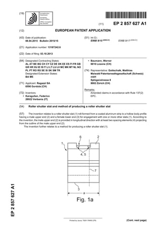
Fig. 1a is a side elevation of an end section of a slat
according to a first preferred embodiment of the in-
vention,
Fig. 1b is a cross section of the slat of fig. 1a,
Fig. 2a is a side elevation of an end section of a slat
according to a second preferred embodiment of the
invention,
Fig. 2b is a cross section of the slat of fig. 2a,
Fig. 3a is a side elevation of an end section of a slat
according to a third preferred embodiment of the in-
vention,
Fig. 3b is a cross section of the slat of fig. 3a.
Fig. 4a is a side elevation of both end sections of a
slat according to a forth preferred embodiment of the
invention and
Fig. 4b is a cross section of the slat of fig. 4a.
Detailed description of the drawings
[0026] As shown in the figures, a slat 1 according to
the invention has a hollow body profile with a male upper
end 2 and a female lower end 3. The male upper end 2
has a convex shape, whereas the female lower end 3
has a concave shape. Both ends 2, 3 are adapted to
engage with correspondingly shaped ends of adjacent
slats linked together to form a vertically moveable roller
shutter. By engagement, the male upper end 2 of first
slat 1 contacts the female lower end 3 of second slat 1.
[0027] The hollow body profile is made from a coated
aluminum strip by roll-forming. Usually, the coating is a
water-based coating deposited on the side of the alumi-
num strip becomingtheoutside of thehollow body profile.
Due to the coating, conventional roller shutter slats tend
to stick together when exposed to high temperatures, e.
g. temperaturesof 35°Candmore. Thisproblemissolved
by a roller shutter comprising a plurality of slats 1 accord-
ing to the present invention.
[0028] A slat 1 according to the present invention is
provided in longitudinal direction withat least two spacing
elements 4 projecting from the outline of the male upper
end 2 of the hollow body profile. The spacing elements
4 reduce the area of contact between the male upper end
2 of a first slat 1 with a female lower end 3 of a second
slat 1 to the exterior surfaces of the spacing elements 4.
Thus, there is no planar or linear contact between the
two slats 1 over their entire length.
[0029] The slats 1 shown in figures 1a to 4b are pro-
vided with spacing elements 4, of which each spacing
element 4 comprises at least one pair of noses 5 project-
ing from the outline of the male upper end 2 of the hollow
body profile. The noses 5 have been created by punching
and bending the coated aluminum strip roll-formed to a
hollow body profile. Thus, each nose 5 is located next to
an opening 6. The opening 6 may serve to receive a belt,
a cord or a strap for linking the slat 1 with a plurality of
other slats 1.
Fig. 1a and 1b show a first preferred embodiment of
a slat 1 according to the present invention. As can
be seen in fig. 1a, the spacing element 4 is located
near an end section a of the slat 1 with regard to its
longitudinal extension. The spacing element 4 com-
prises two pairs of noses 5 each pair flanking a cen-
trally arranged opening 6 with regard to the cross-
section of the slat 1 (see fig. 1b). The opening 6 has
the form of a slot. Both ends of the slot are provided
with a pair of noses 5 having a smaller longitudinal
extensionthantheopening6(seefig.1a). Twonoses
5 flanking the opening 6 and forming a pair of noses
5 are lying in a sectional plane 7 (see fig. 1a), i. e.
on both sides of the hollow body profile when looking
at the cross-section (see fig. 1b). As can be seen in
fig. 1b, the hollow body profile of the slat 1 is filled
with a thermal and acoustic insulation material 8.
Fig. 2a and 2b show a second preferred embodiment
of aslat 1according to the present invention. It differs
from the embodiment shown in fig. 1a and 1b in that
the male upper end 2 has no centrally arranged
opening 6 but two openings 6 on opposite sides of
the hollow body profile (see fig. 2b). The openings 6
are located near an end section b of the slat 1 with
regardtoitslongitudinal extension(see fig. 2a). Each
5 6
6. EP 2 857 627 A1
6
5
10
15
20
25
30
35
40
45
50
55
opening 6 is provided at both ends with a nose 5
which forms a pair of noses 5 with a corresponding
nose 5onthe oppositesideof the hollowbodyprofile.
Fig. 3a and 3b show a third preferred embodiment
of a slat 1 according tothe present invention. It differs
from the embodiments shown in fig. 1a to 2b in that
the spacing element 4 located near an end section
b of the slat 1 with regard to its longitudinal extension
comprises only one pair of noses 5 flanking an open-
ing 6 (see fig. 3b). The pair of noses 5 is arranged
centrally with regard to the longitudinal extension of
the opening 6 (see fig. 3a). Each nose is cut free on
three sides (see fig. 3a), which facilitates bending of
the material in order to form the noses 5.
Fig. 4a and 4b show a forth preferred embodiment
of a slat 1 according to the present invention. In fig.
4a, both end sections a, b of slat 1 are shown. Each
end section a, b is provided with a spacing element
4 projecting from the outline of the male upper end
2 of the hollow body profile comprising two pairs of
noses 5 flanking an opening 6 (see fig. 4b). Each
nose is cut free on two sides (see fig. 4a), which
facilitates bending of the material in order to form the
noses 5.
[0030] All figures show examples of preferred embod-
iments of the invention. Modifications and/or combina-
tions of features are possible and fall within the scope of
invention. Modifications may relate to the shape of the
hollow body profile, its male upper end 2 and/or its female
lower end3.Theymayfurther relate tothe number,shape
or location of the noses 5 and/or the openings 6.
Reference list
[0031]
1 slat
2 male upper end
3 female lower end
4 spacing element
5 nose
6 opening
7 sectional plane
8 thermal and/or acoustic insulation material
Claims
1. Roller shutter slat (1) roll-formed from a coated alu-
minum strip to a hollow body profile having a male
upper end (2) and a female lower end (3) for engage-
ment with one or more other slats (1),
characterized in that the male upper end (2) is pro-
vided in longitudinal direction with at least two spac-
ing elements (4) projecting from the outline of the
male upper end (2).
2. Roller shutter slat according to claim 1,
characterized in that at least one spacing element
(4) is located near an end section (a, b) of the roller
shutter slat (1) with regard to its longitudinal exten-
sion.
3. Roller shutter slat according to claim 1 or 2,
characterized in that the spacing elements (4) are
made from the coated aluminum strip of the hollow
body profile by punching and bending the profile.
4. Roller shutter slat according to one of the preceding
claims,
characterized in that each spacing element (4)
comprises at least one nose (5) projecting from the
outline of the male upper end (2) next to an opening
(6) of the hollow body profile.
5. Roller shutter slat according to one of the preceding
claims,
characterized in that each spacing element (4)
comprises a pair of noses (5) projecting from the
outline of the male upper end (2) and flanking a cen-
trally arranged opening (6) or a plurality of openings
(6) of the hollow body pofile lying within a sectional
plane (7).
6. Roller shutter slat according to one of the preceding
claims,
characterized in that the hollow body profile is filled
with a thermal and/or acoustic insulation material (8),
preferably with plastic foam material, most prefera-
bly with polyurethane.
7. Roller shutter for solar protection comprising at least
two slats (1) according to one of the preceding
claims,wherein theslatsareverticallymovablesuch,
that in a closed position a male upper end (2) of a
first slat (1) engages with a female lower end (3) of
a second slat (1).
8. Method for producing a roller shutter slat (1) from a
coated aluminum strip, comprising the steps
- roll-forming the coated aluminum strip to a hol-
low body profile having a male upper end (2)
and a female lower end (3),
- punching the male upper end (2) in order to
create an opening (6) and
- at least partly bending an edge of the opening
(6) in order to form a nose (5) projecting from
the outline of the male upper end (2) of the slat
(1).
9. Method according to claim 8,
characterized in that the coated aluminum strip is
7 8
7. EP 2 857 627 A1
7
5
10
15
20
25
30
35
40
45
50
55
punched in a central region of the male upper end
(2) with regard to its cross-section to create a cen-
trally arranged opening (6) and two opposite edges
of the opening (6) are at least partly bent in order to
form a pair of noses (5) projecting from the outline
of the male upper end (2) flanking the opening (6).
10. Method according to claim 8 or 9,
characterized in that the hollow body profile is filled
with a thermal and/or acoustic material (8), prefera-
bly with plastic foam, most preferably with poly-
urethane.
11. Method according to claim 10,
characterized in that the hollow body profile is filled
with the thermal and/or acoustic material (8) before
punching and bending the roller shutter slat.
Amended claims in accordance with Rule 137(2)
EPC.
1. Roller shutter slat (1) roll-formed from a coated alu-
minum strip to a hollow body profile having a male
upper end (2) and a female lower end (3) for engage-
ment with one or more other slats (1),
characterized in that the male upper end (2) is pro-
vided in longitudinal direction with at least two spac-
ing elements (4) projecting from the outline of the
male upper end (2), whereby each spacing element
(4) comprises at least one nose (5) projecting from
the outline of the male upper end (2) next to an open-
ing (6) of the hollow body profile.
2. Roller shutter slat according to claim 1,
characterized in that at least one spacing element
(4) is located near an end section (a, b) of the roller
shutter slat (1) with regard to its longitudinal exten-
sion.
3. Roller shutter slat according to claim 1 or 2,
characterized in that the spacing elements (4) are
made from the coated aluminum strip of the hollow
body profile by punching and bending the profile.
4. Roller shutter slat according to one of the preceding
claims,
characterized in that each spacing element (4)
comprises a pair of noses (5) projecting from the
outline of the male upper end (2) and flanking a cen-
trally arranged opening (6) or a plurality of openings
(6) of the hollow body pofile lying within a sectional
plane (7).
5. Roller shutter slat according to one of the preceding
claims,
characterized in that the hollow body profile is filled
witha thermal and/or acousticinsulation material (8),
preferably with plastic foam material, most prefera-
bly with polyurethane.
6. Roller shutter for solar protection comprising at least
two slats (1) according to one of the preceding
claims,wherein theslatsareverticallymovablesuch,
that in a closed position a male upper end (2) of a
first slat (1) engages with a female lower end (3) of
a second slat (1).
7. Method for producing a roller shutter slat (1) from a
coated aluminum strip, comprising the steps
- roll-forming the coated aluminum strip to a hol-
low body profile having a male upper end (2)
and a female lower end (3),
- punching the male upper end (2) in order to
create an opening (6) and
- at least partly bending an edge of the opening
(6) in order to form a nose (5) projecting from
the outline of the male upper end (2) of the slat
(1).
8. Method according to claim 7,
characterized in that the coated aluminum strip is
punched in a central region of the male upper end
(2) with regard to its cross-section to create a cen-
trally arranged opening (6) and two opposite edges
of the opening (6) are at least partly bent in order to
form a pair of noses (5) projecting from the outline
of the male upper end (2) flanking the opening (6).
9. Method according to claim 7 or 8,
characterized in that the hollow body profile is filled
with a thermal and/or acoustic material (8), prefera-
bly with plastic foam, most preferably with poly-
urethane.
10. Method according to claim 9,
characterized in that the hollow body profile is filled
with the thermal and/or acoustic material (8) before
punching and bending the roller shutter slat.
9 10
13. EP 2 857 627 A1
13
REFERENCES CITED IN THE DESCRIPTION
This list of references cited by the applicant is for the reader’s convenience only. It does not form part of the European
patent document. Even though great care has been taken in compiling the references, errors or omissions cannot be
excluded and the EPO disclaims all liability in this regard.
Patent documents cited in the description
• EP 0365908 A1 [0004]