SlideShare a Scribd company logo
1 of 10
Download to read offline
US006899360B1
(12) United States Patent (16) Patent No.: US 6,899,360 B1
Flynn (45) Date of Patent: May 31, 2005
(54) HOSE WITH SERVICEABLE MOLDED-ON 5,388,321 A 2/1995 Farrell
HOSE CLAMP 5,388,872 A * 2/1995 Campo et a1. ............ .. 285/253
5,456,784 A 10/1995 Cogdill et a1.
(75) Inventor: Robert Joseph Flynn, Farmington 1513357253 E 5/1996 Work?’ et a1
Hills MI (Us) 5,616,205 A 4/1997 Cogdill et a1.
’ 5,622,391 A 4/1997 Belik
(73) Assignee: Avon PrOPBrtY Management Co., 2 * ‘hglelnefdlng, SI- ------------ 138/99' a : ebb
Cadlnac> MI (Us) 5,915,739 A 6/1999 Cradduck et a1.
* _ _ _ _ _ 6,390,136 B1 * 5/2002 Hutchins et a1. .......... .. 138/109
( ) Notlcel sublectto any dlsclalmeratheterm Ofthls 6,530,609 B1 * 3/2003 Chatterton ........ 285/420
patent 1s extended or adjusted under 35 2004/0066033 A1 * 4/2004 Rier et a1. .................. .. 285/23
U.S.C. 154 b b 0 da 5.
( ) y y * cited by examiner
(21) Appl. No.: 10/248,755 Primary Examiner—Aaron DunWoody
(22) Filed Feb 14 2003 (74) Attorney, Agent, or Firm—McGarry Bair PC. . ,
(57) ABSTRACT
Related US. Application Data
(60) Provisional application No. 60/357,458, ?led on Feb. 15, A hose and clamp assembly comprises a hose, a band-type
2002- clamp encircling the hose, and an elastomeric envelope
(51) Int. c1.7 ................................................. F16L 25/00 home?‘ to the hose and attaching the Clamp to .the hose ab“?
(52) US‘ Cl‘ 285/420 285/3 285/252 21 section oi the clamp band. The' elastomeric envelope is
"""""""""""""" ’ ’ 285/915’ pkrffvided With at leasthonebdisc?ntmuity tkolde?ne a remov
_ a e center section W ere t e remova e center section
(58) Field Of Search .......................... 285/23, 236, 420, can be Separated along the £16m one discontinuity to form
285/3’ 252’ 253’ 242’ 915’ 156/66’ 383’ an open channel in the envelope and enable removal of the
138/99’ 109 clamp. The at least one discontinuity can comprise a groove
(56) References Cited or a plurality of perforations. The at least one discontinuity
can comprise parallel grooves aligned With the edges of the
US, PATENT DOCUMENTS clamp band to de?ne the removable center section. A chan
nel is formed in the envelope by the removal of the remov
able center section and the clamp to provide a receptacle for
proper positioning of the replacement clamp on the hose.
3,365,218 A * 1/1968 Denyes ..................... .. 285/253
5,002,094 A 3/1991 Brovont
5,145,218 A 9/1992 Worley et 211.
5,234,233 A 8/1993 Fix
5,247,967 A * 9/1993 Bourque .................... .. 138/99 15 Claims, 6 Drawing Sheets
42
12
U.S. Patent May 31, 2005 Sheet 1 6f 6 US 6,899,360 B1
42
lI
A7720 "1
' '///7 '
t
1220
Fig. 1A
U.S. Patent May 31, 2005 Sheet 2 6f 6 US 6,899,360 B1
Fig. 2
U.S. Patent May 31, 2005 Sheet 3 6f 6 US 6,899,360 B1
U.S. Patent May 31, 2005 Sheet 4 6f 6 US 6,899,360 B1
U.S. Patent May 31, 2005 Sheet 5 6f 6 US 6,899,360 B1
Fig. 5
U.S. Patent May 31, 2005 Sheet 6 6f 6 US 6,899,360 B1
US 6,899,360 B1
1
HOSE WITH SERVICEABLE MOLDED-ON
HOSE CLAMP
CROSS REFERENCE TO RELATED
APPLICATIONS
This application claims the bene?t of US. provisional
application Ser. No. 60/357,458, ?led Feb. 15, 2002, Which
is incorporated herein in its entirety.
BACKGROUND OF INVENTION
1. Field of the Invention
The invention relates to hose and clamp assemblies. In
one aspect, the invention relates to a hose and clamp
assembly in Which a clamp is attached to a hose With an
elastomeric envelope that is bonded to the hose and Which
comprises a removable portion to enable the clamp to be
removed and replaced.
2. Description of the Related Art
A?eXible hose and clamp assembly is commonly utiliZed
to provide a ?uid-tight connection of separate ?uid
containing components. The opposite ends of the hose
project over respective ?ttings on the components to a
sufficient eXtent to enable a subsequently installed hose
clamp to tightly engage the hose end about the ?tting for a
?uid-tight connection. It is common to provide the hose and
clamp assembly With clamps that are securely attached at the
proper position on the end of the hose to ensure that the
clamp is readily available When needed and in the proper
position for producing a ?uid-tight connection When the
hose and clamp assembly is installed.
One such device and method for providing a clamp
attached to a hose is described in US. Pat. No. 5,002,094,
entitled “Hose And Clamp Assembly And Method For
Making The Same,” issued to D. A. Brovont on Mar. 26,
1991, Which is incorporated herein by reference.
US. Pat. No. 5,002,094 describes a hose and clamp
assembly in Which a conventional hose clamp is attached to
the hose along a section of the clamp band With an elasto
meric envelope that envelops the clamp band and is bonded
to the hose. The elastomeric envelope may be adhesively
bonded to or integrally vulcaniZed on the hose, and thus
retains the clamp in the proper circumferential and longitu
dinal position on the hose. The elastomeric envelope is of a
strength and thickness suf?cient to keep the clamp from
being accidentally removed from the hose assembly.
There are times When it is desirable to remove and replace
the clamp, such as When the clamp breaks, or becomes
corroded or rusted so as to be unusable. In such
circumstances, it is necessary to remove at least that portion
of the elastomeric envelope overlying the clamp in order to
remove the clamp. HoWever, the elastomeric envelope is
generally of such a thickness and strength that the elasto
meric envelope cannot be torn aWay to enable the removal
of the overlying portion. Thus, the overlying portion must be
cut aWay With a sharpened implement, such as a utility knife,
a dif?cult and time consuming process. if care is not taken
during the cutting process, the hose can be damaged. if the
entire elastomeric envelope is cut aWay, the replacement
clamp may be placed on the hose in the Wrong position for
a ?uid-tight connection When the hose and clamp are rein
stalled on the ?tting. As an alternative to selective removal
of the clamp, the entire hose and clamp assembly can be
removed and discarded. HoWever, this results in unaccept
able Waste if the hose and one of the clamps are still usable.
Therefore, it Would be useful to provide an elastomeric
envelope having a portion overlying the clamp band Which
10
15
20
25
30
35
40
45
55
60
65
2
is easily removable so that the clamp can be readily removed
and replaced With a neW clamp in the proper position on the
hose to provide a ?uid-tight connection When the hose and
clamp assembly is reinstalled.
SUMMARY OF THE INVENTION
Ahose and clamp assembly comprises a hose, a band-type
clamp encircling the hose, and an elastomeric envelope
bonded to the hose and attaching the clamp to the hose along
a section of the clamp band. The elastomeric envelope is
provided With at least one discontinuity to de?ne a remov
able center section Whereby the removable center section
can be separated along the at least one discontinuity to
enable removal of the clamp. The at least one discontinuity
can comprise a groove or a plurality of perforations. The at
least one discontinuity can comprise parallel grooves
aligned With the edges of the clamp band to de?ne the
removable center section. An open channel is formed in the
envelope by the removal of the removable center section and
the clamp to provide a receptacle for proper positioning of
a replacement clamp on the hose.
In another embodiment, a clamp is positioned against a
substrate Whereby the clamping force can be selectively
increased or decreased, and an envelope encapsulates a
portion of-the clamp and is bonded to the substrate for
retaining the clamp against the substrate, Wherein the enve
lope comprises at least one discontinuity so that a portion of
the envelope can be separated along the at least one discon
tinuity to enable removal of the clamp.
In yet another embodiment, a clamp retainer and replace
ment system for retaining a clamp against a substrate With an
envelope and enabling replacement of the clamp by remov
ing a portion of the envelope With a cutting tool comprises
a clamp adapted to be positioned against the substrate
Whereby the clamping force can be selectively increased or
decreased, an envelope encapsulating a portion of the clamp
and adapted to be bonded to the substrate for retaining the
clamp against the substrate Wherein the envelope comprises
parallel grooves to enable a removable center section of the
envelope to be separated along the parallel grooves, and a
cutting tool comprising at least one cutter blade adapted to
sever the removable center section along the parallel
grooves and thereby enable the removal of the removable
center section and the clamp. The cutting tool can comprise
a contact block for controlling the penetration of the at least
one cutter blade through the envelope.
BRIEF DESCRIPTION OF DRAWINGS
In the draWings:
FIG. 1 is a perspective vieW of a section of a hose and
clamp assembly according to the invention.
FIG. 1A is a cross-sectional vieW of the hose and clamp
assembly of FIG. 1 taken along line 1A—1A.
FIG. 2 is a plan vieW of the hose and clamp assembly of
FIG. 1 shoWing the alignment of the groves in the elasto
meric envelope.
FIG. 3 is a side elevational vieW of the hose and clamp
assembly of FIG. 2 shoWing a cutting tool positioned to cut
the elastomeric envelope for removal of the clamp.
FIG. 4 is a perspective vieW of the hose of FIG. 1 shoWing
a channel formed in the elastomeric envelope after a portion
of the elastomeric envelope and the clamp have been
removed.
FIG. 5 is a plan vieW of the hose and clamp assembly
according to a second embodiment of the invention.
US 6,899,360 B1
3
FIG. 6 is a perspective vieW of the hose and clamp
assembly of FIG. 5 showing a center portion of the elasto
meric envelope being pulled away from the hose.
DETAILED DESCRIPTION
Turning to the drawings, and in particular to FIG. 1, the
invention comprises a hose and clamp assembly designated
generally by the reference numeral 10, comprising a hose
12, a hose clamp 14, and an elastomeric envelope 24. The
elastomeric envelope 24 has a-Weakened area for selective
removable of a portion of the envelope for replacement of
the hose clamp 14. A cutting tool can be used to remove the
removable portion to facilitate removal and replacement of
the clamp 14, as hereinafter described.
The clamp 14 is attached to the hose 12 through an
elastomeric envelope 24 that overlies a portion of the clamp
band 20. Hose and clamp assemblies for use in engine
coolant hoses, fuel ?ller hoses, fuel line hoses, air induction
hoses, transmission lines, air injection tubes, drain hoses,
Washing machine hoses, and ?uid or air conveyance tubes or
hoses generally can be assembled according to the inven
tion. Any clamp, preferably having at least one hole, notch,
slot or perforation in the band or having a lug, clamp screW
housing, socket, or similar means for enabling or facilitating
the tightening of the clamp around the end of a hose can be
suitably employed according to the invention. In the
embodiments shoWn in FIGS. 1—4, the hose clamp 14
comprises a conventional radiator hose POPP clamp 14
having a clamp band 20 With a tongue ?ange 16 at one end
and a holding ?ange 18 at another end. The tongue ?ange 16
is received in a slot 22 and has a shoulder 18 abuts the
holding ?ange 18 When the clamp is in an open condition
around the hose 12.
The clamp 14 is formed of any suitable metallic material
that has natural spring force to tend to circumferentially
move apart a pair of end portions 16 and 18 thereof so as to
shrink the de?ning circumference of an annular band 20
thereof from a relatively large circumference de?ned
thereby When the ends 16 and 18 are toggled together in the
manner illustrated in FIG. 1 to a smaller diameter con?gu
ration When the end projections 16 and 18 are released from
each other so that the clamp Will move to its clamping
condition in a manner Well knoWn in the hose construction
art. See, for example, Muhr US. Pat. No. 4,773,129 and
Hashimoto et al. US. Pat. No. 4,425,682, Which are incor
porated herein by reference. See also the Worley et al. US.
Pat. No. 5,145,218 and the Cogdill et al. US. Pat. No.
5,616,205. The hose clamp 14 can be any suitable type of
clamp as, for example disclosed in the Fix US. Pat. No.
5,234,233, Which is incorporated herein by reference. These
clamps include the screW clamps and POPP clamps.
As shoWn in FIGS. 1A and 2, the elastomeric envelope 24
comprises a top Wall 26 having an undersurface 27, and
lateral Walls 28 extending generally doWnWardly orthogonal
to the top Wall 26. The lateral Walls 28 are bonded to the
outer surface of the hose 12, thereby creating a closed
channel 30 extending betWeen the opposite ends of the
envelope 24 and oriented along the circumference of the
hose 12. The channel 30 forms an elongated passageWay in
Which the clamp band 20 is received.
The envelope 24 is provided With at least one disconti
nuity in the top Wall 26 comprising in this ?rst embodiment
a pair of parallel grooves 32 in spaced-apart relationship
extending doWnWardly from the top Wall 26 toWard the
undersurface 27 and having a loWer groove ?oor 33. The
grooves 32 extend circumferentially betWeen the opposite
10
15
20
25
30
35
40
45
55
60
65
4
ends of the envelope 24. As shoWn in FIG. 3, the grooves 32
are generally in vertical alignment With the edges of the
clamp band 20 and de?ne an envelope center portion 42.
As described in US. Pat. No. 5,002,094, the envelope is
either bonded to the hose by vulcaniZation or an adhesive.
The hose 12 and the envelope 24 are preferably fabricated of
the same elastomeric material, although the hose 12 and
envelope 24 can comprise different materials. Suitable elas
tomeric materials include, but are not limited to, ethylene
propylene terpolymer, butadiene acrylonitrile, chlorosul
fonated polyethylene, chloroprene, epichlorohydrin,
polyisoprene, styrene butadiene, chlorinated polyethylene,
ethylene acrylic, polysiloxanes, ?uorosilicones,
polyacrylates, and ?uoronated hydrocarbons.
As shoWn in FIG. 3, a cutting tool 34 comprises a cutter
head 36 and a cutter support base 40 for cutting through the
top Wall 26 to remove the center portion 42. The cutter head
36 is a rigid block-like member adapted to rigidly hold tWo
cutter blades 38 in a spaced-apart parallel alignment corre
sponding generally to the spaced-apart alignment of the
grooves 32. The blades 38 are separated from each other a
distance generally equal to the distance separating the
grooves 32 so that the blades 38 are received Within the
grooves 32 When the cutter head 36 is brought into engage
ment With the envelope 24. In the preferred embodiment, the
Width of the cut de?ned by the blades 38 is 0.5 millimeters
less than the Width of the clamp band 20.
The cutter head 36 is also provided With a contact block
37 located intermediate the blades 38 and extending the
length of the cutter head 36. The cutter blades 38 are
positioned relative to the contact block 37 so that When the
contact block 37 is brought into contact With the top Wall 26
the blades 38 penetrate through the portion of the envelope
24 overlying the band 20 sufficient to separate the center
portion 42 from the rest of the top Wall 26 but Without
penetrating into the hose 12.
The cutter support base 40 comprises a rigid elongated
member having an upper arcuate surface 41 and adapted to
be inserted into the hose 12 to support the hose 12 and
envelope 24 during the envelope cutting process. The hose
12 rests upon the support base 40 so that the doWnWard
pressure of the cutter head 36 against the envelope 24 can be
resisted in order to facilitate an accurate cut. The cutting tool
34 can be adapted to be utiliZed in an automated, poWer
driven device, or operated by hand.
In operation, the hose end is typically removed from the
associated ?tting, and the cutter support base 40 is inserted
into the hose 12 to contact the interior of the hose adjacent
to the envelope 24. The hose 12 is held against the cutter
support base 40 to provide a solid base against Which the
cutter head 31 can operate during the cutting procedure. The
cutter head 36 is then used to cut through the groove ?oors
33 to separate the center portion 42 from the rest of the
envelope 24. The grooves 32 are utiliZed to properly align
the cutter head 36 relative to the center portion 42. The depth
of cut is controlled by bringing the contact block 37 into
contact With the top Wall 26. After the cutting operation has
been completed, the center portion 42 can be readily
removed, exposing the clamp band 20 and enabling the
removal of the clamp 14 from the hose 12. As shoWn in FIG.
4, the removal of the center portion 42 and the clamp 14
forms an open channel 44 for removal of a defective band
and for receipt of a replacement clamp 14, Which is properly
positioned With respect to the end of the hose 12 by receipt
of the clamp band 20 in the channel 44.
Referring noW to FIGS. 5 and 6, a second embodiment of
the invention is shoWn. The envelopes in both embodiments
US 6,899,360 B1
5
are similar except that in the second embodiment a plurality
of perforations 46 penetrates the envelope 24 in a line along
each groove 32 extending from the ?oor 33 of the groove 32
to the closed channel 30. The perforations 46 are adapted in
siZe and spacing to enable the center section 42 to be readily
pulled from the remainder of the envelope 24 Without the use
of a cutting tool, While providing sufficient strength to
maintain the attachment of the center section 42 to the
envelope 24 to secure the clamp 14 onto the hose 12 until it
is desirable to selectively remove the center section 42. At
least one pull tab 48 is provided at least one end of the center
section 42 to facilitate grasping and pulling of the center
section 42 to remove the center section 42 from the envelope
24. As With the ?rst embodiment, upon removal of the center
section 42, the clamp 14 can be removed and replaced. The
channel 44 formed by removal of the center portion 42 and
the clamp 14 provides for proper positioning of a replace
ment clamp With respect to the end of the hose 12.
The removable patch retains the advantages of attaching
the clamp to the hose, but provides a convenient means of
removing the clamp from the hose When the clamp must be
replaced. The specialiZed cutting tool provides for an ef?
cient and accurate means of removing the center section of
the envelope. The grooves in the envelope facilitate the
proper alignment of the cutting tool With the clamp band,
and the effective removal of that portion of the envelope
necessary for removal of the clamp. The channel formed by
the removal of the center section of the envelope provides a
convenient means of properly positioning a replacement
clamp on the hose to ensure the proper securing of the hose
to the associated ?tting in order to maintain a ?uid-tight
connection. Alternatively, the use of perforations along the
grooves and a pull-tab enable the center portion of the
envelope to be removed Without the necessity of a cutting
tool.
While particular embodiments of the invention have been
shoWn, it Will be understood that the invention is not limited
thereto. Reasonable variation and modi?cation are possible
Within the scope of the foregoing disclosure and draWings,
particulary in light of the foregoing teachings, Without
departing from the spirit of the invention Which is de?ned in
the appended claims.
What is claimed is:
1. In a hose and clamp assembly comprising:
a hose;
a clamp encircling a portion of the hose; and
an elastomeric envelope bonded to the hose and encap
sulating only a portion of the clamp;
the improvement comprising:
the envelope has in an outer radial surface thereof at least
one circumferential groove or a plurality of circumfer
entially spaced perforations that facilitates the separa
tion of a portion of the envelope along the at least one
circumferential groove or circunferentially spaced per
forations to enable removal and replacement of the
clamp.
2. The hose and clamp assembly of claim 1 Wherein the
at least one circumferential groove comprises parallel cir
cumferential grooves in a top surface of the envelope
aligned With the edges of the clamp to de?ne a removable
center section to enable removal and replacement of the
clamp.
3. The hose and clamp assembly of claim 2 Wherein an
open channel is formed in the envelope by the removal of the
removable center section and the clamp to provide a recep
tacle for proper positioning of a replacement clamp on the
hose.
15
25
35
40
45
55
65
6
4. The hose and clamp assembly of claim 1 Wherein the
envelope is formed of the same material as the hose.
5. The hose and clamp assembly of claim 1 Wherein the
hose is a rubber automotive coolant hose.
6. The hose and clamp assembly of claim 1 Wherein the
hose is an automotive fuel ?ller hose.
7. A clamp assembly for applying a clamping force
against a hose, comprising:
a clamp positioned against the hose for applying a clamp
ing force to the hose; and
an envelope encapsulating a portion of the clamp and
bonded to the hose for retaining the clamp against the
hose;
Wherein the envelope comprises in an outer radial surface
thereof at least one discontinuity in the form of a
circumferential groove or a plurality of circumferential
perforations so that a portion of the envelope can be
separated along the at least one discontinuity to enable
removal and replacement of the clamp.
8. The clamp assembly of claim 7 Wherein the at least one
discontinuity comprises parallel circumferential grooves in a
top surface of the envelope aligned With the edges of the
clamp to de?ne a removable center section to enable
removal and replacement of the clamp.
9. The clamp assembly of claim 8 Wherein an open
channel is formed in the envelope by the removal of the
removable center section and the clamp to provide a recep
tacle for proper positioning of a replacement clamp on the
hose.
10. The clamp assembly of claim 7 Wherein the envelope
is formed of the same material as the substrate.
11. The hose and clamp assembly of claim 7 Wherein the
hose is a rubber automotive coolant hose.
12. The hose and clamp assembly of claim 7 Wherein the
hose is an automotive fuel ?ller hose.
13. Aclamp retainer and replacement system for retaining
a clamp against a substrate With an envelope and enabling
replacement of the clamp by removing a portion of the
envelope With a cutting tool, comprising
a clamp positioned against the substrate for applying a
clamping force to the substrate;
an envelope encapsulating a portion of the clamp and
bonded to the substrate for retaining the clamp against
the substrate Wherein the envelope comprises at least
one groove or a plurality of circumferential perfora
tions to enable a center section of the envelope to be
separated along the groove; and
a cutting tool comprising at least one cutter blade adapted
to sever the removable center section along the at least
one groove or circumferential perforations and thereby
enable the separation of the center section from the
envelope and removal of the clamp.
14. The clamp retainer and replacement system of claim
13 Wherein the cutting tool further comprises a contact block
for controlling the penetration of the at least one cutter blade
through the envelope.
15. The clamp retainer and replacement system of claim
13 Wherein there are tWo grooves or circumferential perfo
rations that are parallel to each other and the cutting tool has
tWo cutter blades spaced apart a distance to register With the
tWo grooves or circumferential perforations, and the tWo
cutter blades are adapted to simultaneously sever the enve
lope at the tWo parallel groves or circumferential perfora
tions.

More Related Content

What's hot

4316 4320.output
4316 4320.output4316 4320.output
4316 4320.outputj1075017
 
4301 4305.output
4301 4305.output4301 4305.output
4301 4305.outputj1075017
 
4401 4405.output
4401 4405.output4401 4405.output
4401 4405.outputj1075017
 
Memo 55b-rvk-101-rekommended-reinforcement-pattern
Memo 55b-rvk-101-rekommended-reinforcement-patternMemo 55b-rvk-101-rekommended-reinforcement-pattern
Memo 55b-rvk-101-rekommended-reinforcement-patternS.s. Lee
 
Memo 55c-tss-41-rekommended-reinforcement-pattern
Memo 55c-tss-41-rekommended-reinforcement-patternMemo 55c-tss-41-rekommended-reinforcement-pattern
Memo 55c-tss-41-rekommended-reinforcement-patternS.s. Lee
 
4306 4310.output
4306 4310.output4306 4310.output
4306 4310.outputj1075017
 
4521 4525.output
4521 4525.output4521 4525.output
4521 4525.outputj1075017
 
55 daniel david dobrinski - 6303861 - connector for connecting a conductor ...
55   daniel david dobrinski - 6303861 - connector for connecting a conductor ...55   daniel david dobrinski - 6303861 - connector for connecting a conductor ...
55 daniel david dobrinski - 6303861 - connector for connecting a conductor ...Mello_Patent_Registry
 
Basic rules for rcc design
Basic rules for rcc designBasic rules for rcc design
Basic rules for rcc designMandar Nadgaundi
 
Us20060265924
Us20060265924Us20060265924
Us20060265924Jin Song
 
4956 4960.output
4956 4960.output4956 4960.output
4956 4960.outputj1075017
 
内圆击锤
内圆击锤内圆击锤
内圆击锤Jin Song
 
4811 4815.output
4811 4815.output4811 4815.output
4811 4815.outputj1075017
 
5011 5015.output
5011 5015.output5011 5015.output
5011 5015.outputj1075017
 
Base plate and anchor design
Base plate and anchor designBase plate and anchor design
Base plate and anchor designBalázs Kisfali
 
4906 4910.output
4906 4910.output4906 4910.output
4906 4910.outputj1075017
 
Welding Cable Joint
Welding Cable JointWelding Cable Joint
Welding Cable JointMax Zhou
 

What's hot (20)

4316 4320.output
4316 4320.output4316 4320.output
4316 4320.output
 
4301 4305.output
4301 4305.output4301 4305.output
4301 4305.output
 
4401 4405.output
4401 4405.output4401 4405.output
4401 4405.output
 
Memo 55b-rvk-101-rekommended-reinforcement-pattern
Memo 55b-rvk-101-rekommended-reinforcement-patternMemo 55b-rvk-101-rekommended-reinforcement-pattern
Memo 55b-rvk-101-rekommended-reinforcement-pattern
 
Memo 55c-tss-41-rekommended-reinforcement-pattern
Memo 55c-tss-41-rekommended-reinforcement-patternMemo 55c-tss-41-rekommended-reinforcement-pattern
Memo 55c-tss-41-rekommended-reinforcement-pattern
 
4306 4310.output
4306 4310.output4306 4310.output
4306 4310.output
 
Ep0314509 a2
Ep0314509 a2Ep0314509 a2
Ep0314509 a2
 
4521 4525.output
4521 4525.output4521 4525.output
4521 4525.output
 
55 daniel david dobrinski - 6303861 - connector for connecting a conductor ...
55   daniel david dobrinski - 6303861 - connector for connecting a conductor ...55   daniel david dobrinski - 6303861 - connector for connecting a conductor ...
55 daniel david dobrinski - 6303861 - connector for connecting a conductor ...
 
Basic rules for rcc design
Basic rules for rcc designBasic rules for rcc design
Basic rules for rcc design
 
Us20060265924
Us20060265924Us20060265924
Us20060265924
 
4956 4960.output
4956 4960.output4956 4960.output
4956 4960.output
 
内圆击锤
内圆击锤内圆击锤
内圆击锤
 
4811 4815.output
4811 4815.output4811 4815.output
4811 4815.output
 
5011 5015.output
5011 5015.output5011 5015.output
5011 5015.output
 
Base plate and anchor design
Base plate and anchor designBase plate and anchor design
Base plate and anchor design
 
Details of REINFORCEMENT Summary
Details of REINFORCEMENT SummaryDetails of REINFORCEMENT Summary
Details of REINFORCEMENT Summary
 
4906 4910.output
4906 4910.output4906 4910.output
4906 4910.output
 
Welding Cable Joint
Welding Cable JointWelding Cable Joint
Welding Cable Joint
 
780149
780149780149
780149
 

Similar to Molded Hose Clamp Removal

4501 4505.output
4501 4505.output4501 4505.output
4501 4505.outputj1075017
 
5051 5055.output
5051 5055.output5051 5055.output
5051 5055.outputj1075017
 
4331 4335.output
4331 4335.output4331 4335.output
4331 4335.outputj1075017
 
US Patent 7946306
US Patent 7946306 US Patent 7946306
US Patent 7946306 AmpoyoChar
 
19 craig s. mello - 5178559 - stress relief backshell assembly
19   craig s. mello - 5178559 - stress relief backshell assembly19   craig s. mello - 5178559 - stress relief backshell assembly
19 craig s. mello - 5178559 - stress relief backshell assemblyMello_Patent_Registry
 
4246 4250.output
4246 4250.output4246 4250.output
4246 4250.outputj1075017
 
4686 4690.output
4686 4690.output4686 4690.output
4686 4690.outputj1075017
 
USPatent_6390794
USPatent_6390794USPatent_6390794
USPatent_6390794Andrew Chin
 
96 100.output
96 100.output96 100.output
96 100.outputj1075017
 
77 richard j. ericson - 6820726 - traction enhanced controlled pressure fle...
77   richard j. ericson - 6820726 - traction enhanced controlled pressure fle...77   richard j. ericson - 6820726 - traction enhanced controlled pressure fle...
77 richard j. ericson - 6820726 - traction enhanced controlled pressure fle...Mello_Patent_Registry
 
4281 4285.output
4281 4285.output4281 4285.output
4281 4285.outputj1075017
 
21 gerald e. johnson - 5226522 - moving handrail guide mount with vibration...
21   gerald e. johnson - 5226522 - moving handrail guide mount with vibration...21   gerald e. johnson - 5226522 - moving handrail guide mount with vibration...
21 gerald e. johnson - 5226522 - moving handrail guide mount with vibration...Mello_Patent_Registry
 

Similar to Molded Hose Clamp Removal (20)

5386 5390.output
5386 5390.output5386 5390.output
5386 5390.output
 
4501 4505.output
4501 4505.output4501 4505.output
4501 4505.output
 
780093
780093780093
780093
 
780093
780093780093
780093
 
5051 5055.output
5051 5055.output5051 5055.output
5051 5055.output
 
4331 4335.output
4331 4335.output4331 4335.output
4331 4335.output
 
US7946306 (7)
US7946306 (7)US7946306 (7)
US7946306 (7)
 
US Patent 7946306
US Patent 7946306 US Patent 7946306
US Patent 7946306
 
19 craig s. mello - 5178559 - stress relief backshell assembly
19   craig s. mello - 5178559 - stress relief backshell assembly19   craig s. mello - 5178559 - stress relief backshell assembly
19 craig s. mello - 5178559 - stress relief backshell assembly
 
Screw and Barrel Inspection
Screw and Barrel InspectionScrew and Barrel Inspection
Screw and Barrel Inspection
 
4246 4250.output
4246 4250.output4246 4250.output
4246 4250.output
 
4686 4690.output
4686 4690.output4686 4690.output
4686 4690.output
 
USPatent_6390794
USPatent_6390794USPatent_6390794
USPatent_6390794
 
96 100.output
96 100.output96 100.output
96 100.output
 
77 richard j. ericson - 6820726 - traction enhanced controlled pressure fle...
77   richard j. ericson - 6820726 - traction enhanced controlled pressure fle...77   richard j. ericson - 6820726 - traction enhanced controlled pressure fle...
77 richard j. ericson - 6820726 - traction enhanced controlled pressure fle...
 
4281 4285.output
4281 4285.output4281 4285.output
4281 4285.output
 
21 gerald e. johnson - 5226522 - moving handrail guide mount with vibration...
21   gerald e. johnson - 5226522 - moving handrail guide mount with vibration...21   gerald e. johnson - 5226522 - moving handrail guide mount with vibration...
21 gerald e. johnson - 5226522 - moving handrail guide mount with vibration...
 
Us4989289
Us4989289Us4989289
Us4989289
 
US20130014858
US20130014858US20130014858
US20130014858
 
单发
单发单发
单发
 

Molded Hose Clamp Removal

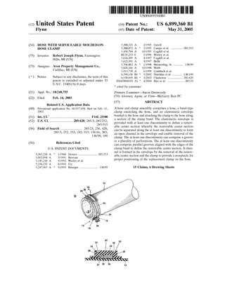
  • 1. US006899360B1 (12) United States Patent (16) Patent No.: US 6,899,360 B1 Flynn (45) Date of Patent: May 31, 2005 (54) HOSE WITH SERVICEABLE MOLDED-ON 5,388,321 A 2/1995 Farrell HOSE CLAMP 5,388,872 A * 2/1995 Campo et a1. ............ .. 285/253 5,456,784 A 10/1995 Cogdill et a1. (75) Inventor: Robert Joseph Flynn, Farmington 1513357253 E 5/1996 Work?’ et a1 Hills MI (Us) 5,616,205 A 4/1997 Cogdill et a1. ’ 5,622,391 A 4/1997 Belik (73) Assignee: Avon PrOPBrtY Management Co., 2 * ‘hglelnefdlng, SI- ------------ 138/99' a : ebb Cadlnac> MI (Us) 5,915,739 A 6/1999 Cradduck et a1. * _ _ _ _ _ 6,390,136 B1 * 5/2002 Hutchins et a1. .......... .. 138/109 ( ) Notlcel sublectto any dlsclalmeratheterm Ofthls 6,530,609 B1 * 3/2003 Chatterton ........ 285/420 patent 1s extended or adjusted under 35 2004/0066033 A1 * 4/2004 Rier et a1. .................. .. 285/23 U.S.C. 154 b b 0 da 5. ( ) y y * cited by examiner (21) Appl. No.: 10/248,755 Primary Examiner—Aaron DunWoody (22) Filed Feb 14 2003 (74) Attorney, Agent, or Firm—McGarry Bair PC. . , (57) ABSTRACT Related US. Application Data (60) Provisional application No. 60/357,458, ?led on Feb. 15, A hose and clamp assembly comprises a hose, a band-type 2002- clamp encircling the hose, and an elastomeric envelope (51) Int. c1.7 ................................................. F16L 25/00 home?‘ to the hose and attaching the Clamp to .the hose ab“? (52) US‘ Cl‘ 285/420 285/3 285/252 21 section oi the clamp band. The' elastomeric envelope is """""""""""""" ’ ’ 285/915’ pkrffvided With at leasthonebdisc?ntmuity tkolde?ne a remov _ a e center section W ere t e remova e center section (58) Field Of Search .......................... 285/23, 236, 420, can be Separated along the £16m one discontinuity to form 285/3’ 252’ 253’ 242’ 915’ 156/66’ 383’ an open channel in the envelope and enable removal of the 138/99’ 109 clamp. The at least one discontinuity can comprise a groove (56) References Cited or a plurality of perforations. The at least one discontinuity can comprise parallel grooves aligned With the edges of the US, PATENT DOCUMENTS clamp band to de?ne the removable center section. A chan nel is formed in the envelope by the removal of the remov able center section and the clamp to provide a receptacle for proper positioning of the replacement clamp on the hose. 3,365,218 A * 1/1968 Denyes ..................... .. 285/253 5,002,094 A 3/1991 Brovont 5,145,218 A 9/1992 Worley et 211. 5,234,233 A 8/1993 Fix 5,247,967 A * 9/1993 Bourque .................... .. 138/99 15 Claims, 6 Drawing Sheets 42 12
  • 2. U.S. Patent May 31, 2005 Sheet 1 6f 6 US 6,899,360 B1 42 lI A7720 "1 ' '///7 ' t 1220 Fig. 1A
  • 3. U.S. Patent May 31, 2005 Sheet 2 6f 6 US 6,899,360 B1 Fig. 2
  • 4. U.S. Patent May 31, 2005 Sheet 3 6f 6 US 6,899,360 B1
  • 5. U.S. Patent May 31, 2005 Sheet 4 6f 6 US 6,899,360 B1
  • 6. U.S. Patent May 31, 2005 Sheet 5 6f 6 US 6,899,360 B1 Fig. 5
  • 7. U.S. Patent May 31, 2005 Sheet 6 6f 6 US 6,899,360 B1
  • 8. US 6,899,360 B1 1 HOSE WITH SERVICEABLE MOLDED-ON HOSE CLAMP CROSS REFERENCE TO RELATED APPLICATIONS This application claims the bene?t of US. provisional application Ser. No. 60/357,458, ?led Feb. 15, 2002, Which is incorporated herein in its entirety. BACKGROUND OF INVENTION 1. Field of the Invention The invention relates to hose and clamp assemblies. In one aspect, the invention relates to a hose and clamp assembly in Which a clamp is attached to a hose With an elastomeric envelope that is bonded to the hose and Which comprises a removable portion to enable the clamp to be removed and replaced. 2. Description of the Related Art A?eXible hose and clamp assembly is commonly utiliZed to provide a ?uid-tight connection of separate ?uid containing components. The opposite ends of the hose project over respective ?ttings on the components to a sufficient eXtent to enable a subsequently installed hose clamp to tightly engage the hose end about the ?tting for a ?uid-tight connection. It is common to provide the hose and clamp assembly With clamps that are securely attached at the proper position on the end of the hose to ensure that the clamp is readily available When needed and in the proper position for producing a ?uid-tight connection When the hose and clamp assembly is installed. One such device and method for providing a clamp attached to a hose is described in US. Pat. No. 5,002,094, entitled “Hose And Clamp Assembly And Method For Making The Same,” issued to D. A. Brovont on Mar. 26, 1991, Which is incorporated herein by reference. US. Pat. No. 5,002,094 describes a hose and clamp assembly in Which a conventional hose clamp is attached to the hose along a section of the clamp band With an elasto meric envelope that envelops the clamp band and is bonded to the hose. The elastomeric envelope may be adhesively bonded to or integrally vulcaniZed on the hose, and thus retains the clamp in the proper circumferential and longitu dinal position on the hose. The elastomeric envelope is of a strength and thickness suf?cient to keep the clamp from being accidentally removed from the hose assembly. There are times When it is desirable to remove and replace the clamp, such as When the clamp breaks, or becomes corroded or rusted so as to be unusable. In such circumstances, it is necessary to remove at least that portion of the elastomeric envelope overlying the clamp in order to remove the clamp. HoWever, the elastomeric envelope is generally of such a thickness and strength that the elasto meric envelope cannot be torn aWay to enable the removal of the overlying portion. Thus, the overlying portion must be cut aWay With a sharpened implement, such as a utility knife, a dif?cult and time consuming process. if care is not taken during the cutting process, the hose can be damaged. if the entire elastomeric envelope is cut aWay, the replacement clamp may be placed on the hose in the Wrong position for a ?uid-tight connection When the hose and clamp are rein stalled on the ?tting. As an alternative to selective removal of the clamp, the entire hose and clamp assembly can be removed and discarded. HoWever, this results in unaccept able Waste if the hose and one of the clamps are still usable. Therefore, it Would be useful to provide an elastomeric envelope having a portion overlying the clamp band Which 10 15 20 25 30 35 40 45 55 60 65 2 is easily removable so that the clamp can be readily removed and replaced With a neW clamp in the proper position on the hose to provide a ?uid-tight connection When the hose and clamp assembly is reinstalled. SUMMARY OF THE INVENTION Ahose and clamp assembly comprises a hose, a band-type clamp encircling the hose, and an elastomeric envelope bonded to the hose and attaching the clamp to the hose along a section of the clamp band. The elastomeric envelope is provided With at least one discontinuity to de?ne a remov able center section Whereby the removable center section can be separated along the at least one discontinuity to enable removal of the clamp. The at least one discontinuity can comprise a groove or a plurality of perforations. The at least one discontinuity can comprise parallel grooves aligned With the edges of the clamp band to de?ne the removable center section. An open channel is formed in the envelope by the removal of the removable center section and the clamp to provide a receptacle for proper positioning of a replacement clamp on the hose. In another embodiment, a clamp is positioned against a substrate Whereby the clamping force can be selectively increased or decreased, and an envelope encapsulates a portion of-the clamp and is bonded to the substrate for retaining the clamp against the substrate, Wherein the enve lope comprises at least one discontinuity so that a portion of the envelope can be separated along the at least one discon tinuity to enable removal of the clamp. In yet another embodiment, a clamp retainer and replace ment system for retaining a clamp against a substrate With an envelope and enabling replacement of the clamp by remov ing a portion of the envelope With a cutting tool comprises a clamp adapted to be positioned against the substrate Whereby the clamping force can be selectively increased or decreased, an envelope encapsulating a portion of the clamp and adapted to be bonded to the substrate for retaining the clamp against the substrate Wherein the envelope comprises parallel grooves to enable a removable center section of the envelope to be separated along the parallel grooves, and a cutting tool comprising at least one cutter blade adapted to sever the removable center section along the parallel grooves and thereby enable the removal of the removable center section and the clamp. The cutting tool can comprise a contact block for controlling the penetration of the at least one cutter blade through the envelope. BRIEF DESCRIPTION OF DRAWINGS In the draWings: FIG. 1 is a perspective vieW of a section of a hose and clamp assembly according to the invention. FIG. 1A is a cross-sectional vieW of the hose and clamp assembly of FIG. 1 taken along line 1A—1A. FIG. 2 is a plan vieW of the hose and clamp assembly of FIG. 1 shoWing the alignment of the groves in the elasto meric envelope. FIG. 3 is a side elevational vieW of the hose and clamp assembly of FIG. 2 shoWing a cutting tool positioned to cut the elastomeric envelope for removal of the clamp. FIG. 4 is a perspective vieW of the hose of FIG. 1 shoWing a channel formed in the elastomeric envelope after a portion of the elastomeric envelope and the clamp have been removed. FIG. 5 is a plan vieW of the hose and clamp assembly according to a second embodiment of the invention.
  • 9. US 6,899,360 B1 3 FIG. 6 is a perspective vieW of the hose and clamp assembly of FIG. 5 showing a center portion of the elasto meric envelope being pulled away from the hose. DETAILED DESCRIPTION Turning to the drawings, and in particular to FIG. 1, the invention comprises a hose and clamp assembly designated generally by the reference numeral 10, comprising a hose 12, a hose clamp 14, and an elastomeric envelope 24. The elastomeric envelope 24 has a-Weakened area for selective removable of a portion of the envelope for replacement of the hose clamp 14. A cutting tool can be used to remove the removable portion to facilitate removal and replacement of the clamp 14, as hereinafter described. The clamp 14 is attached to the hose 12 through an elastomeric envelope 24 that overlies a portion of the clamp band 20. Hose and clamp assemblies for use in engine coolant hoses, fuel ?ller hoses, fuel line hoses, air induction hoses, transmission lines, air injection tubes, drain hoses, Washing machine hoses, and ?uid or air conveyance tubes or hoses generally can be assembled according to the inven tion. Any clamp, preferably having at least one hole, notch, slot or perforation in the band or having a lug, clamp screW housing, socket, or similar means for enabling or facilitating the tightening of the clamp around the end of a hose can be suitably employed according to the invention. In the embodiments shoWn in FIGS. 1—4, the hose clamp 14 comprises a conventional radiator hose POPP clamp 14 having a clamp band 20 With a tongue ?ange 16 at one end and a holding ?ange 18 at another end. The tongue ?ange 16 is received in a slot 22 and has a shoulder 18 abuts the holding ?ange 18 When the clamp is in an open condition around the hose 12. The clamp 14 is formed of any suitable metallic material that has natural spring force to tend to circumferentially move apart a pair of end portions 16 and 18 thereof so as to shrink the de?ning circumference of an annular band 20 thereof from a relatively large circumference de?ned thereby When the ends 16 and 18 are toggled together in the manner illustrated in FIG. 1 to a smaller diameter con?gu ration When the end projections 16 and 18 are released from each other so that the clamp Will move to its clamping condition in a manner Well knoWn in the hose construction art. See, for example, Muhr US. Pat. No. 4,773,129 and Hashimoto et al. US. Pat. No. 4,425,682, Which are incor porated herein by reference. See also the Worley et al. US. Pat. No. 5,145,218 and the Cogdill et al. US. Pat. No. 5,616,205. The hose clamp 14 can be any suitable type of clamp as, for example disclosed in the Fix US. Pat. No. 5,234,233, Which is incorporated herein by reference. These clamps include the screW clamps and POPP clamps. As shoWn in FIGS. 1A and 2, the elastomeric envelope 24 comprises a top Wall 26 having an undersurface 27, and lateral Walls 28 extending generally doWnWardly orthogonal to the top Wall 26. The lateral Walls 28 are bonded to the outer surface of the hose 12, thereby creating a closed channel 30 extending betWeen the opposite ends of the envelope 24 and oriented along the circumference of the hose 12. The channel 30 forms an elongated passageWay in Which the clamp band 20 is received. The envelope 24 is provided With at least one disconti nuity in the top Wall 26 comprising in this ?rst embodiment a pair of parallel grooves 32 in spaced-apart relationship extending doWnWardly from the top Wall 26 toWard the undersurface 27 and having a loWer groove ?oor 33. The grooves 32 extend circumferentially betWeen the opposite 10 15 20 25 30 35 40 45 55 60 65 4 ends of the envelope 24. As shoWn in FIG. 3, the grooves 32 are generally in vertical alignment With the edges of the clamp band 20 and de?ne an envelope center portion 42. As described in US. Pat. No. 5,002,094, the envelope is either bonded to the hose by vulcaniZation or an adhesive. The hose 12 and the envelope 24 are preferably fabricated of the same elastomeric material, although the hose 12 and envelope 24 can comprise different materials. Suitable elas tomeric materials include, but are not limited to, ethylene propylene terpolymer, butadiene acrylonitrile, chlorosul fonated polyethylene, chloroprene, epichlorohydrin, polyisoprene, styrene butadiene, chlorinated polyethylene, ethylene acrylic, polysiloxanes, ?uorosilicones, polyacrylates, and ?uoronated hydrocarbons. As shoWn in FIG. 3, a cutting tool 34 comprises a cutter head 36 and a cutter support base 40 for cutting through the top Wall 26 to remove the center portion 42. The cutter head 36 is a rigid block-like member adapted to rigidly hold tWo cutter blades 38 in a spaced-apart parallel alignment corre sponding generally to the spaced-apart alignment of the grooves 32. The blades 38 are separated from each other a distance generally equal to the distance separating the grooves 32 so that the blades 38 are received Within the grooves 32 When the cutter head 36 is brought into engage ment With the envelope 24. In the preferred embodiment, the Width of the cut de?ned by the blades 38 is 0.5 millimeters less than the Width of the clamp band 20. The cutter head 36 is also provided With a contact block 37 located intermediate the blades 38 and extending the length of the cutter head 36. The cutter blades 38 are positioned relative to the contact block 37 so that When the contact block 37 is brought into contact With the top Wall 26 the blades 38 penetrate through the portion of the envelope 24 overlying the band 20 sufficient to separate the center portion 42 from the rest of the top Wall 26 but Without penetrating into the hose 12. The cutter support base 40 comprises a rigid elongated member having an upper arcuate surface 41 and adapted to be inserted into the hose 12 to support the hose 12 and envelope 24 during the envelope cutting process. The hose 12 rests upon the support base 40 so that the doWnWard pressure of the cutter head 36 against the envelope 24 can be resisted in order to facilitate an accurate cut. The cutting tool 34 can be adapted to be utiliZed in an automated, poWer driven device, or operated by hand. In operation, the hose end is typically removed from the associated ?tting, and the cutter support base 40 is inserted into the hose 12 to contact the interior of the hose adjacent to the envelope 24. The hose 12 is held against the cutter support base 40 to provide a solid base against Which the cutter head 31 can operate during the cutting procedure. The cutter head 36 is then used to cut through the groove ?oors 33 to separate the center portion 42 from the rest of the envelope 24. The grooves 32 are utiliZed to properly align the cutter head 36 relative to the center portion 42. The depth of cut is controlled by bringing the contact block 37 into contact With the top Wall 26. After the cutting operation has been completed, the center portion 42 can be readily removed, exposing the clamp band 20 and enabling the removal of the clamp 14 from the hose 12. As shoWn in FIG. 4, the removal of the center portion 42 and the clamp 14 forms an open channel 44 for removal of a defective band and for receipt of a replacement clamp 14, Which is properly positioned With respect to the end of the hose 12 by receipt of the clamp band 20 in the channel 44. Referring noW to FIGS. 5 and 6, a second embodiment of the invention is shoWn. The envelopes in both embodiments
  • 10. US 6,899,360 B1 5 are similar except that in the second embodiment a plurality of perforations 46 penetrates the envelope 24 in a line along each groove 32 extending from the ?oor 33 of the groove 32 to the closed channel 30. The perforations 46 are adapted in siZe and spacing to enable the center section 42 to be readily pulled from the remainder of the envelope 24 Without the use of a cutting tool, While providing sufficient strength to maintain the attachment of the center section 42 to the envelope 24 to secure the clamp 14 onto the hose 12 until it is desirable to selectively remove the center section 42. At least one pull tab 48 is provided at least one end of the center section 42 to facilitate grasping and pulling of the center section 42 to remove the center section 42 from the envelope 24. As With the ?rst embodiment, upon removal of the center section 42, the clamp 14 can be removed and replaced. The channel 44 formed by removal of the center portion 42 and the clamp 14 provides for proper positioning of a replace ment clamp With respect to the end of the hose 12. The removable patch retains the advantages of attaching the clamp to the hose, but provides a convenient means of removing the clamp from the hose When the clamp must be replaced. The specialiZed cutting tool provides for an ef? cient and accurate means of removing the center section of the envelope. The grooves in the envelope facilitate the proper alignment of the cutting tool With the clamp band, and the effective removal of that portion of the envelope necessary for removal of the clamp. The channel formed by the removal of the center section of the envelope provides a convenient means of properly positioning a replacement clamp on the hose to ensure the proper securing of the hose to the associated ?tting in order to maintain a ?uid-tight connection. Alternatively, the use of perforations along the grooves and a pull-tab enable the center portion of the envelope to be removed Without the necessity of a cutting tool. While particular embodiments of the invention have been shoWn, it Will be understood that the invention is not limited thereto. Reasonable variation and modi?cation are possible Within the scope of the foregoing disclosure and draWings, particulary in light of the foregoing teachings, Without departing from the spirit of the invention Which is de?ned in the appended claims. What is claimed is: 1. In a hose and clamp assembly comprising: a hose; a clamp encircling a portion of the hose; and an elastomeric envelope bonded to the hose and encap sulating only a portion of the clamp; the improvement comprising: the envelope has in an outer radial surface thereof at least one circumferential groove or a plurality of circumfer entially spaced perforations that facilitates the separa tion of a portion of the envelope along the at least one circumferential groove or circunferentially spaced per forations to enable removal and replacement of the clamp. 2. The hose and clamp assembly of claim 1 Wherein the at least one circumferential groove comprises parallel cir cumferential grooves in a top surface of the envelope aligned With the edges of the clamp to de?ne a removable center section to enable removal and replacement of the clamp. 3. The hose and clamp assembly of claim 2 Wherein an open channel is formed in the envelope by the removal of the removable center section and the clamp to provide a recep tacle for proper positioning of a replacement clamp on the hose. 15 25 35 40 45 55 65 6 4. The hose and clamp assembly of claim 1 Wherein the envelope is formed of the same material as the hose. 5. The hose and clamp assembly of claim 1 Wherein the hose is a rubber automotive coolant hose. 6. The hose and clamp assembly of claim 1 Wherein the hose is an automotive fuel ?ller hose. 7. A clamp assembly for applying a clamping force against a hose, comprising: a clamp positioned against the hose for applying a clamp ing force to the hose; and an envelope encapsulating a portion of the clamp and bonded to the hose for retaining the clamp against the hose; Wherein the envelope comprises in an outer radial surface thereof at least one discontinuity in the form of a circumferential groove or a plurality of circumferential perforations so that a portion of the envelope can be separated along the at least one discontinuity to enable removal and replacement of the clamp. 8. The clamp assembly of claim 7 Wherein the at least one discontinuity comprises parallel circumferential grooves in a top surface of the envelope aligned With the edges of the clamp to de?ne a removable center section to enable removal and replacement of the clamp. 9. The clamp assembly of claim 8 Wherein an open channel is formed in the envelope by the removal of the removable center section and the clamp to provide a recep tacle for proper positioning of a replacement clamp on the hose. 10. The clamp assembly of claim 7 Wherein the envelope is formed of the same material as the substrate. 11. The hose and clamp assembly of claim 7 Wherein the hose is a rubber automotive coolant hose. 12. The hose and clamp assembly of claim 7 Wherein the hose is an automotive fuel ?ller hose. 13. Aclamp retainer and replacement system for retaining a clamp against a substrate With an envelope and enabling replacement of the clamp by removing a portion of the envelope With a cutting tool, comprising a clamp positioned against the substrate for applying a clamping force to the substrate; an envelope encapsulating a portion of the clamp and bonded to the substrate for retaining the clamp against the substrate Wherein the envelope comprises at least one groove or a plurality of circumferential perfora tions to enable a center section of the envelope to be separated along the groove; and a cutting tool comprising at least one cutter blade adapted to sever the removable center section along the at least one groove or circumferential perforations and thereby enable the separation of the center section from the envelope and removal of the clamp. 14. The clamp retainer and replacement system of claim 13 Wherein the cutting tool further comprises a contact block for controlling the penetration of the at least one cutter blade through the envelope. 15. The clamp retainer and replacement system of claim 13 Wherein there are tWo grooves or circumferential perfo rations that are parallel to each other and the cutting tool has tWo cutter blades spaced apart a distance to register With the tWo grooves or circumferential perforations, and the tWo cutter blades are adapted to simultaneously sever the enve lope at the tWo parallel groves or circumferential perfora tions.