Download to read offline

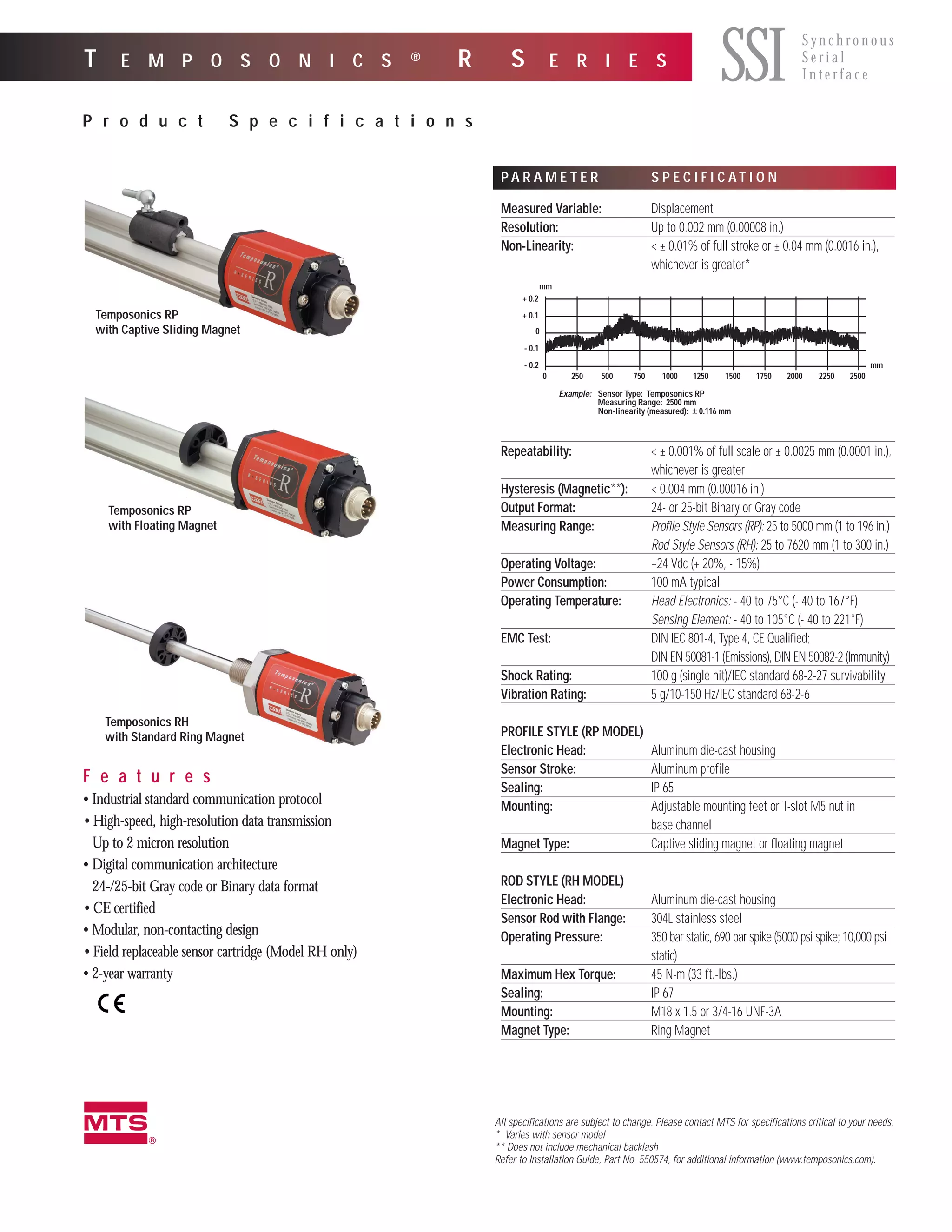
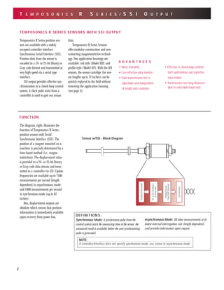

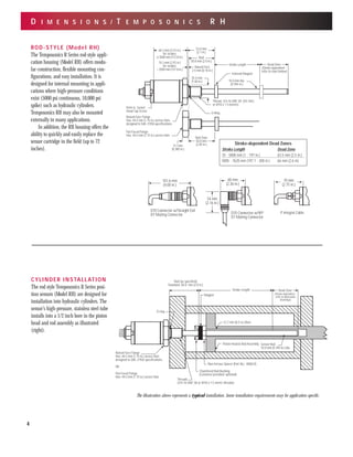
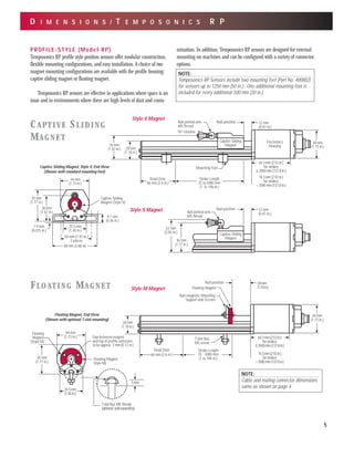
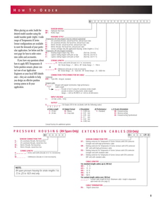

This document provides specifications for Temposonics R Series position sensors that use a Synchronous Serial Interface (SSI) for output. Key details include: - SSI is a serial interface that uses a clock pulse train from a controller to transmit 24- or 25-bit position data from the sensor one bit at a time. - Temposonics R Series sensors offer modular construction and non-contacting magnetostrictive technology in either a rod style (Model RH) or profile style (Model RP) housing. - Specifications include resolutions up to 2 microns, operating temperatures from -40°C to 105°C, IP65/IP67 sealing, and measuring ranges from 25


