2. 4
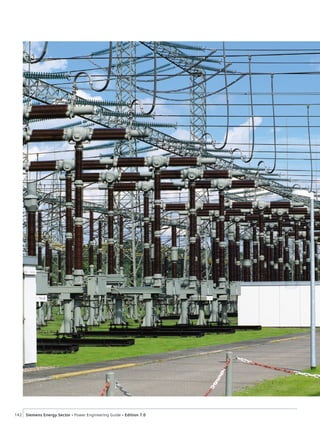
143Siemens Energy Sector Power Engineering Guide Edition 7.0
Products and Devices
4.1 High Voltage Circuit Breakers 144
4.1.1 Circuit Breakers for 72.5 kV up to 800 kV 144
4.1.2 Live-Tank Circuit Breakers
for 72.5 kV up to 800 kV 148
4.1.3 Dead-Tank Circuit Breakers
for 72.5 kV up to 550 kV 151
4.1.4. The DTC – Dead Tank Compact –
a Compact Switchgear up to 245 kV 154
4.1.5. The DCB – Disconnecting Circuit Breaker 156
4.2 High Voltage Disconnectors 158
4.2.1 Disconnectors and Earthing Switches 158
4.3 Vacuum Switching Technology and
Components for Medium Voltage 167
4.3.1 Overview of Vacuum Switching Components 167
4.3.2 Selection of Components by Ratings 168
4.3.3 Vacuum Circuit-Breakers 170
4.3.4 Vacuum Circuit-Breaker for
Generator Switching Application 175
4.3.5 Outdoor Vacuum Circuit-Breakers 176
4.3.6 Reclosers 177
4.3.7 Vacuum Contactors 178
4.3.8 Contactor-Fuse Combination 179
4.3.9 Disconnectors and Switch-Disconnectors 182
4.3.10 Earthing Switches 183
4.4 Low-Voltage Devices 184
4.4.1 Requirements on the Switchgear
in the Three Circuit Types 184
4.4.2 Low-Voltage Protection and Switching Devices 186
4.4.3 Busbar Trunking Systems, Cables and Wires 188
4.4.4 Subdistribution Systems 196
4.5 Surge Arresters 199
4.5.1 High-Voltage Surge Arresters 199
4.5.2 Low-Voltage and Medium-Voltage
Surge Arresters and Limiters 201
4.6 Instrument Transformers 204
4.6.1 High-Voltage Instrument Transformers 204
4.6.2 Power Voltage Transformers 211
4.7 Coil Products (HV) 219
4.8 Bushings 222
4.8.1 High-Voltage Bushings 222
4.9 Medium-Voltage Fuses 226
4.10 Silicone Long Rod Insulators 227
4.10.1 3FL Long Rod Insulators 227
3. 144 Siemens Energy Sector Power Engineering Guide Edition 7.0
4
4.1.1 Circuit Breakers
for 72.5 kV up to 800 kV
Circuit breakers are the central part of AIS and GIS switchgear.
They have to meet high requirements in terms of:
Reliable opening and closing
Consistent quenching performance with rated and short-circuit
currents even after many switching operations
High-performance, reliable, maintenance-free operating
mechanisms.
Technology reflecting the latest state of the art and years of
operating experience are put to use in constant further develop-
ment and optimization of Siemens circuit breakers. This makes
Siemens circuit breakers able to meet all the demands placed on
high-voltage switchgear.
The comprehensive quality system is certified according to
DIN EN ISO 9001. It covers development, manufacturing, sales,
commissioning and after-sales service. Test laboratories are
accredited to EN 45001 and PEHLA/STL.
The modular design
Circuit breakers for air-insulated switchgear are individual com-
ponents, and are assembled together with all individual elec-
trical and mechanical components of an AIS installation on site.
Due to the consistent application of a modular design, all
Siemens circuit breaker types, whether air-insulated or gas-insu-
lated, are made up of the same range of components based on
our well-proven platform design (fig. 4.1-1):
Interrupter unit
Operating mechanism
Sealing system
Operating rod
Control elements.
Interrupter unit –
self-compression arc-quenching principle
The Siemens product range from 72.5 kV up to 800 kV includes
high-voltage circuit breakers with self-compression interrupter
units – for optimum switching performance under every oper-
ating condition for every voltage level.
Self-compression circuit breakers
3AP high-voltage circuit breakers for the complete voltage range
ensure optimum use of the thermal energy of the arc in the
contact cylinder. This is achieved by the self-compression inter-
rupter unit.
Siemens patented this method for arc quenching in 1973. Since
that time, Siemens has continued to develop the technology of
the self-compression interrupter unit. One of its technical inno-
vations is that the arc energy is increasingly used to extinguish
the arc. In short-circuit breaking operations, the actuating
energy required is reduced to the energy needed for mechanical
contact movement.
That means that the operating energy is truly minimized. The
self-compression interrupter unit allows the use of a compact
stored-energy spring mechanism that provides unrestricted high
dependability.
Stored-energy spring mechanism –
for the complete product range
The operating mechanism is a central part of the high-voltage
circuit breakers. The drive concept of the 3AP high-voltage
circuit breakers is based on the stored-energy spring principle.
The use of such an operating mechanism for voltage ranges of
up to 800 kV became appropriate as a result of the development
of a self-compression interrupter unit that requires minimal
actuating energy.
Advantages of the stored-energy spring mechanism are:
Highest degree of operational safety: It is a simple and sturdy
design and uses the same principle for rated voltages from
72.5 kV up to 800 kV with just a few moving parts. Due to the
self-compression design of the interrupter unit, only low
actuating forces are required.
Availability and long service life: Minimal stressing of the latch
mechanisms and rolling-contact bearings in the operating
mechanism ensure reliable and wear-free transmission of
forces.
Maintenance-free design: The spring charging gear is fitted
with wear-free spur gears, enabling load-free decoupling.
Siemens circuit breakers for rated voltage levels from 72.5 kV up
to 800 kV are equipped with self-compression interrupter units
and stored-energy spring mechanisms.
For special technical requirements such as rated short-circuit
breaking currents of 80 kA, Siemens can offer twin-nozzle circuit
breaker series 3AQ or 3AT with an electrohydraulic mechanism.
4 Products and Devices
4.1 High Voltage
Circuit Breakers
4. Products and Devices
4.1 High Voltage Circuit Breakers
145Siemens Energy Sector Power Engineering Guide Edition 7.0
4
Fig. 4.1-1: Circuit-breaker parts: circuit-breaker for air-insulated switchgear (top), circuit-breaker in SF6-insulated switchgear (bottom)
Circuit-breaker in
SF6-insulated switchgear
Circuit-breaker for
air-insulated switchgear
Control
elements
Operating
mechanism
Interrupter
unit
5. Products and Devices
4.1 High Voltage Circuit Breakers
146 Siemens Energy Sector Power Engineering Guide Edition 7.0
4
The interrupter unit: self-compression system
The conducting path
The current conducting path of the interrupter unit consists of
the contact support (2), the base (7) and the movable contact
cylinder (6). In the closed position, the current flows via the
main contact (4) and the contact cylinder (6); (fig. 4.1-2).
Breaking operating currents
During the opening operation, the main contact (4) opens first,
and the current commutates to the still closed arcing contact.
During the further course of opening, the arcing contact (5)
opens and an arc is drawn between the contacts. At the same
time, the contact cylinder (6) moves into the base (7) and
compresses the SF6 gas located there. This gas compression
creates a gas flow through the contact cylinder (6) and the
nozzle (3) to the arcing contact, extinguishing the arc.
Breaking fault currents
In the event of interrupting high short-circuit breaking currents,
the SF6 gas is heated up considerably at the arcing contact due
to the energy of the arc. This leads to a pressure increase in the
contact cylinder. During the further course of opening, this
increased pressure initiates a gas flow through the nozzle (3),
extinguishing the arc. In this case, the arc energy is used to
interrupt the fault current. This energy needs not be provided by
the operating mechanism.
Major features:
Self-compression interrupter unit
Use of the thermal energy of the arc
Minimized energy consumption
High reliability for a long time.
The operating mechanism
Stored-energy spring mechanism
Siemens circuit breakers for voltages up to 800 kV are equipped
with stored-energy spring mechanisms. These operating mecha-
nisms are based on the same principle that has been proving its
worth in Siemens low-voltage and medium-voltage circuit
breakers for decades. The design is simple and robust, with few
moving parts and a vibration-isolated latch system of the highest
reliability. All components of the operating mechanism, the
control and monitoring equipment and all terminal blocks are
arranged in a compact and convenient way in one cabinet.
Depending on the design of the operating mechanism, the
energy required for switching is provided by individual compres-
sion springs (i.e., one per pole) or by springs that function
jointly on a 3-pole basis.
Fig. 4.1-2: The interrupter unit
2
3
4
5
6
7
Opening
Arcing contact open
1
8
1 Terminal plate
2 Contact support
3 Nozzle
4 Main contact
5 Arcing contact
6 Contact cylinder
7 Base
8 Terminal plate
Closed position
Opening
Main contact open
Open position
6. Products and Devices
4.1 High Voltage Circuit Breakers
147Siemens Energy Sector Power Engineering Guide Edition 7.0
4
The principle of the operating mechanism with charging gear
and latching is identical on all types (fig. 4.1-3, fig. 4.1-4).
Differences between mechanism types are in the number, size
and arrangement of the opening and closing springs.
Main features at a glance:
Uncomplicated, robust construction with few moving parts
Maintenance-free
Vibration-isolated latches
Load-free uncoupling of charging mechanism
Easy access
10,000 operating cycles.
9
8
10
11
12
13
14
15
16
17
1
2
3
4
5
6
7
13 Operating shaft
14 Damper (for opening)
15 Trip coil OPEN
16 Operating mechanism housing
17 Opening spring
1 Trip coil CLOSE
2 Cam plate
3 Corner gear
4 Connecting rod
5 Connecting rod for closing spring
6 Connecting rod for opening spring
7 Closing spring
8 Emergency hand crank
9 Charging gear
10 Charging shaft
11 Roller lever
12 Damper (for closing)
Fig. 4.1-3: Operating mechanism
Fig. 4.1-4: Control cubicle
7. Products and Devices
4.1 High Voltage Circuit Breakers
148 Siemens Energy Sector Power Engineering Guide Edition 7.0
4
4.1.2 Live-Tank Circuit Breakers
for 72.5 kV up to 800 kV
Live-tank circuit breakers for air-insulated switchgear
All live-tank circuit breakers are of the same general modular
design, as shown in fig. 4.1-5 to fig. 4.1-9.
They consist of the following main components based on our
well established platform concept:
Self-compression interrupter unit
Stored-energy spring mechanism
Insulator column (AIS)
Operating rod
Circuit breaker base
Control unit.
The uncomplicated design of the circuit breakers and the use of
many similar components, such as interrupter units, operating
rods, control cubicles and operating mechanisms, ensure high
reliability. The experience Siemens has gained from the use of
the many circuit breakers in service has been applied in improve-
ment of the design. The self-compression interrupter unit, for
example, has proven its reliability in more than 100,000 installa-
tions all over the world.
The control unit includes all necessary devices for circuit breaker
control and monitoring, such as:
Pressure / SF6 density monitors
Relays for alarms and lockout
Operation counters (upon request)
Local circuit breaker control (upon request)
Anti-condensation heaters.
Transport, installation and commissioning are performed with
expertise and efficiency. The routine-tested circuit breaker is
dismantled into a few subassemblies for transportation.
If desired, Siemens can provide appropriately qualified personnel
for installation and commissioning.
Fig. 4.1-5: 800 kV circuit breaker pole 3AP4
8. Products and Devices
4.1 High Voltage Circuit Breakers
149Siemens Energy Sector Power Engineering Guide Edition 7.0
4
12
16
16
11
15.1
21 22
22.3922.38
11 Base
12 Control cubicle
15.1 Operating mechanism
housing
16 Post insulator
21 Bell-crank mechanism
22 Interrupter unit
22.38 Corona ring of the
double-break assembly
22.39 Corona ring of the pole
column
Fig. 4.1-6: 550 kV circuit breaker 3AP2FI
15.16.3 2115.11 22 22.1 22.22
16.9
16
16
15.9
15.8.3
15
15 Corner gear
15.11 Filter cowl
15.16.3 Filter bag
15.8.3 Shaft
15.9 Lever
16 Post insulator
16.9 Operating rod
21 Bell-crank
mechanism
22 Interrupter unit
22.1 Jacket
22.22 High-voltage
terminal
Fig. 4.1-7: Sectional view of pole column
Fig. 4.1-8: 145 kV circuit breaker 3AP1FG with 3-pole stored-energy
spring mechanism
4,5
1
2
3
6
1 Interrupter unit
2 Post insulator
3 Circuit-breaker base
4 Control cubicle
5 Operating mechanism housing
6 Pillar
Fig. 4.1-9: 3AP1FG on site
9. Products and Devices
4.1 High Voltage Circuit Breakers
150 Siemens Energy Sector Power Engineering Guide Edition 7.0
4
Table 4.1-1: Technical data of circuit breakers 3AP1, 3AP2 and 3AP4
Type 3AP1 3AP2 3AP4
Rated voltage [kV] 72.5 123 145 170 245 300 362 420 550 800
Number of interrupter units per pole 1 2 4
Rated power-frequency withstand voltage/min [kV] 140 230 275 325 460 460 520 610 800 830
Rated lightning impulse withstand voltage/min [kV] 325 550 650 750 1,050 1,050 1,175 1,425 1,550 2,100
Rated switching impulse withstand voltage/min [kV] – – – – – 850 950 1,050 1,175 1,425
Rated normal current, up to [A] 4,000 4,000 4,000 4,000 4,000 4,000 5,000 5,000 5,000 5,000
Rated short-time withstand current
(1 s – 3 s), up to [kA (rms)]
40 40 40 40 50 40 50 50 63 63
Rated peak withstand current, up to [kA (peak)] 108 108 108 108 135 108 170 170 170 170
Rated short-circuit breaking current, up to [kA (rms)] 40 40 40 40 50 40 63 63 63 63
Rated short-circuit making current, up to [kA (peak)] 108 108 108 108 135 108 170 170 170 170
Temperature range [°C] – 30 or – 40 ... + 40 or + 50
Rated operating sequence 0-0.3 s-CO-3 min-CO or CO-15 s-CO
Rated break time 3 cycles 2 cycles
Rated frequency [Hz] 50/60 50
Type of operating mechanism Stored-energy spring mechanism
Control voltage [V, DC] 48 … 250
Motor voltage [V, DC]
[V, AC]
48/60/110/125/220/250
120 … 240, 50 Hz; 120 … 280, 60 Hz
Flashover distance phase-to-earth [mm]
across open circuit breaker [mm]
700
1,200
1,250
1,200
1,250
1,200
1,500
1,400
1,900
1,900
2,200
2,200
3,400
3,200
3,400
3,200
3,800
3,800
5,850
7,600
Min. creepage distance phase-to-earth [mm]
across open circuit breaker [mm]
2,248
3,625
3,625
3,625
3,625
3,625
4,250
4,250
6,125
6,125
7,626
8,575
10,375
10,500
10,375
10,500
14,450
15,126
20,000
30,352
Dimensions height [mm]
width [mm]
depth [mm]
3,810
3,180
660
4,360
3,880
660
4,360
3,880
660
4,810
4,180
660
6,050
6,640
880
6,870
8,235
880
6,200
8,847
4,380
6,200
9,847
4,380
7,350
13,050
5,050
9,740
19,400
10,470
Phase spacing (min.) [mm] 1,350 1,700 1,700 1,850 2,800 3,600 4,000 4,500 6,000 9,000
Circuit breaker mass [kg] 1,350 1,500 1,500 1,680 2,940 3,340 5,370 5,370 7,160 16,200
Maintenance after 25 years
Values in accordance with IEC; other values available on request
10. Products and Devices
4.1 High Voltage Circuit Breakers
151Siemens Energy Sector Power Engineering Guide Edition 7.0
4
4.1.3 Dead-Tank Circuit Breakers
for 72.5 kV up to 550 kV
Circuit breakers in dead-tank design
For certain substation designs, dead-tank circuit breakers might
be required instead of the standard live-tank circuit breakers.
The main feature of dead-tank technology is that the interrupter
unit is accommodated in an earthed metal housing. The dead-
tank circuit breaker offers particular advantages if the protection
design requires the use of several current transformers per pole
assembly. For this purpose, Siemens can offer dead-tank circuit
breaker types (fig. 4.1-10, fig. 4.1-11).
Main features at a glance:
Reliable opening and closing
– Proven contact and self-compression arc-quenching system
– Consistent quenching performance with rated and short-
circuit currents – even after many switching operations
– Similar uncomplicated design for all voltage levels
High-performance, reliable operating mechanisms
– Easy-to-actuate spring operating mechanisms
– Low maintenance, economical and long service life
Economy
– Perfect finish
– Simplified, quick installation process
– Long maintenance intervals
– High number of operating cycles
– Long service life.
Individual service
– Close proximity to the customer
– Order-specific documentation
– Solutions tailored to specific problems
– After-sales service available promptly worldwide
The right qualifications
– Expertise in all power supply matters
– More than 40 years of experience with SF6-insulated circuit
breakers
– A quality system certified to ISO 9001, covering
development, manufacture, sales, installation and after-
sales service
– Our dead tank circuit breakers are developed according
to the latest version of IEC 62271-1, IEC 62271-100 and
ANSI C37.04, ANSI C37.06, C37.09
– Test laboratories accredited to EN 45001 and PEHLA/STL.
Fig. 4.1-12: SPS2 / 3AP1 dead-tank circuit breaker 362 kV (two-cycles)
Fig. 4.1-10: SPS2 circuit breaker 72.5 kV
Fig. 4.1-11: 3AP1 dead-tank circuit breaker 145 kV
11. Products and Devices
4.1 High Voltage Circuit Breakers
152 Siemens Energy Sector Power Engineering Guide Edition 7.0
4
Dead-tank circuit breaker
Type SPS2 and 3AP DT
The type SPS2 power circuit breakers (table 4.1-2) are used for
the US and ANSI markets, and the 3AP DT breaker types are
offered in IEC markets. Both types are designed as general,
definite-purpose circuit breakers for use at maximum rated
voltages of 72.5 kV up to 550 kV.
The design
Dead-tank circuit breakers (except for the 550 kV version) con-
sist of three identical pole units mounted on a common support
frame. The opening and closing spring of the FA-type operating
mechanism is transferred to the moving contacts of the inter-
rupter unit through a system of connecting rods and a rotating
seal at the side of each phase.
The connection to the overhead lines and busbars is realized by
SF6-insulated air bushings. The insulators are available in either
porcelain or composite (epoxy-impregnated fiberglass tube with
silicone rubber sheds) materials.
The tanks and the bushings are charged with SF6 as at a rated
pressure of 6.0 bar. The SF6 is used for insulation and arc-
quenching purposes.
The 3AP2/3 DT for 550 kV (fig. 4.1-13, fig. 4.1-14) consists of
two interrupter units in a series that features a simple design.
The proven Siemens arc-quenching system ensures faultless
operation, consistently high arc-quenching capacity and a long
service life, even at high switching frequencies.
Thanks to constant further development, optimization and
consistent quality assurance, Siemens self-compression arc-
quenching systems meet all the requirements placed on modern
high-voltage technology.
A control cubicle mounted at one end of the circuit breaker
houses the spring operating mechanism and circuit breaker
control components. The interrupter units are located in the
aluminum housing of each pole unit. The interrupters use the
latest Siemens self-compression arc-quenching system.
The stored-energy spring mechanism is the same design as used
within the Siemens 3AP live-tank circuit breakers, GIS and
compact switchgear. This design has been documented in
service for more than 10 years, and has a well-documented
reliability record.
Operators can specify up to four (in some cases, up to six)
bushing-type current transformers (CT) per phase. These CTs,
mounted externally on the aluminum housings, can be removed
without dismantling the bushings.
Table 4.1-2: Technical data of dead-tank circuit breaker
Technical data
Type 3AP1 DT / SPS2 3AP2/3 DT / SPS2
Rated voltage [kV] 72.5 123 145 245 362 550
Rated power-frequency withstand voltage [kV] 140 / 160 230 / 260 275 / 310 460 520 800 / 860
Rated lighting impulse withstand voltage [kV] 325 / 350 550 650 1,050 1,380 1,865 / 1,800
Rated switching impulse withstand voltage [kV] – – – – 1,095 1,350
Rated nominal current up to [A] 4,000 4,000 4,000 4,000 4,000 4,000 / 5,000
Rated breaking current up to [kA] 40 40 63 63 63 63
Operating mechanism type Stored-energy spring mechanism
12. Products and Devices
4.1 High Voltage Circuit Breakers
153Siemens Energy Sector Power Engineering Guide Edition 7.0
4
22.22
24
28
27
22.1.20
22.1.21
22
23
22.1
15 16.9
22.1.10
26
22.27
22.1.50
15 Corner gear
16.9 Operating rod
22 Interrupter unit
22.1 Housing
22.1.10 Cover
22.1.10.1 Cover
22.1.20 Cover with bursting disc
22.1.21 Cover with filter material
22.1.50 Additional heating
22.22 High-voltage terminal
22.27 Conductor connection
23 Grading capacitor
24 Bushing conductor
26 Closing resistor
27 Current transformer
28 Bushing
Fig. 4.1-13: Sectional view of a 3AP2/3-DT circuit breaker pole
Fig. 4.1-14: 3AP2 DT 550 kV
Operating mechanism
The mechanically and electrically trip-free spring mechanism
type FA is used on type SPS2 and 3AP1/2 DT circuit breakers. The
closing and opening springs are loaded for “O-C-O” operations.
A weatherproofed control cubicle (degree of protection IP55)
has a large door, sealed with rubber gaskets, for easy access
during inspection and maintenance. Condensation is prevented
by heaters that maintain a difference in inside/outside tempera-
ture, and by ventilation.
The control system includes all the secondary technical compo-
nents required for operating the circuit breaker, which are
typically installed in the control cubicle. The current transformer
connections are also located in the control cubicle.
The control, tripping, motor and heating power supplies are
selectable in a great extent. Depending on customer require-
ments, two standard control versions are available.
Basic version
The basic variant includes all control and monitoring elements
that are needed for operation of the circuit breaker. In addition
to the elementary actuation functions, it includes:
19 auxiliary switch contacts (9 normally open, 9 normally
closed, 1 passing contact)
Operations counter
Local actuator.
Compact version
In addition to the basic version, this type includes:
Spring monitoring by motor runtime monitoring
Heating monitoring (current measuring relay)
Luminaire and socket attachment with a common circuit
breaker to facilitate servicing and maintenance work
Overvoltage attenuation
Circuit breaker motor
Circuit breaker heating.
For further information:
Fax: +49 30 3 86-2 02 31
Email: support.energy@siemens.com
or circuit-breaker@siemens.com
13. Products and Devices
4.1 High Voltage Circuit Breakers
154 Siemens Energy Sector Power Engineering Guide Edition 7.0
4
4.1.4. The DTC – Dead Tank Compact –
a Compact Switchgear up to 245 kV
The hybrid concept
The hybrid concept combines SF6-encapsulated components and
air-insulated devices. The application of gas-insulated compo-
nents increases availability of switchgear. According to CIGRE
analyses, gas-insulated components are four times more reliable
than air-insulated components. The level of encapsulation can
be defined in accordance with the requirements of the individual
substation layout and the system operator’s project budget. This
leads to optimized investments and can be combined with
further air-insulated devices.
The modular design
Based on the well-proven modular design, the core components
of the main units are based on the same technology that is used
in the well-established high-voltage circuit breakers, disconnec-
tors and GIS product family of Siemens.
These components are:
Self-compression arc-quenching interrupter unit
of the AIS 3AP circuit breaker
Stored-energy spring mechanism
SF6-insulated disconnector/earthing switch
from the GIS type 8DN8
Outdoor earthing switch from the disconnector
product range (fig. 4.1-15 and fig. 4.1-16).
This allows for providing flexible solutions according to different
substation configurations:
Circuit breaker with single-pole or three-pole operating
mechanism
Disconnector, earthing switch, high-speed earthing switch
Current transformer, voltage transformer and voltage
detecting system
Cable connections possible at various positions
Bushings available as porcelain or composite insulators
Additional separations of gas compartment, with SF6 density
monitor on request
Double breaker modules for ultra compact substation designs
Possibility of combination with stand-alone components, e.g.
disconnector module with voltage transformer (fig. 4.1-17).
Fig. 4.1-16: 3AP1 DTC 145 kV
Fig. 4.1-15: Possible components for the 3AP1 DTC
1. Bushing
2. Current transformer
3. Circuit breaker with self-compression principle
4. Three-position disconnector and earthing switch
5. Voltage transformer
6. Cable connection assembly
7. High-speed earthing switch
2 4
3 6
7
5
1
14. Products and Devices
4.1 High Voltage Circuit Breakers
155Siemens Energy Sector Power Engineering Guide Edition 7.0
4
72
31.5
40
50
63
123 145 170 245 300 362 420 550
Rated voltage (kV)
Ratedshortcircuit-breakingcurrent(kA)
DTC 245 kV
DTC 145 kV
Fig. 4.1-18: DTC product range, 1-pole or 3-pole operation
Table 4.1-3: Technical data of 3AP1 DTC
High-voltage
compact switchgear
3AP1 DTC
Rated voltage [kV] 145 245
Rated normal current [A] 3,150 4,000
Rated frequency [Hz] 50/60 50/60
Rated lightning impulse
withstand voltage [kV] 650 1050
Rated power-frequency
withstand voltage [kV] 275 460
Rated short-time
withstand current (3 s) [kA] 40 63
Rated peak withstand current [kA] 108 170
Highlights and characteristics
Simple SF6 filling and monitoring, one gas compartment
possible (separation optional)
Flexibility in confined spaces and extreme environmental
conditions, e.g. low temperature applications down to –55 °C
Single-pole encapsulation: no 3-phase fault possible and fast
replacement of one pole (spare part: one pole)
Safety can be enhanced by separated gas compartments, e.g.
between circuit breaker and disconnector.
Complete module can be moved with a fork-lift truck
Fast installation and commissioning: easy assembly of fully
manufactured and tested modular units
Less maintenance effort: first major inspection after 25 years
Service life minimum 50 years
Single-pole and three-pole operated drive system for 145 kV
and 245 kV (fig. 4.1-18).
Standard
The international IEC 62271-205 standard treats compact
switchgear assemblies for rated voltages above 52 kV. The used
terminology for the hybrid concept is the so-called mixed tech-
nology switchgear (MTS).
Our compact switchgear is fully type-tested in accordance with
this standard.
We have one of the most modern testing laboratories available
which are certified and part of the European network of inde-
pendent testing organizations (PEHLA).
Also other international testing laboratories (KEMA, CESI) certify
our circuit breakers’ high quality standards (fig. 4.1-19,
table 4.1-3).
Fig. 4.1-17: 3AP1 DTC 245 kV
Fig. 4.1-19: 3AP1 DTC 145 kV with voltage transformer and cable
connection
15. Products and Devices
4.1 High Voltage Circuit Breakers
156 Siemens Energy Sector Power Engineering Guide Edition 7.0
4
4.1.5. The DCB –
Disconnecting Circuit Breaker
ONE device – TWO functions
In switchgear, isolating distances in air combined with circuit
breakers are used to protect the circuit state in the grid.
Siemens developed a combined device in which the isolating
distance has been integrated in the SF6 gas compartment on the
basis of an SF6-insulated circuit breaker in order to reduce
environmental influence. The combined device (DCB – Discon-
necting Circuit breaker) is used as a circuit breaker and addition-
ally as a disconnector – two functions combined in one device
(fig. 4.1-20, fig. 4.1-21).
The DCB was developed on the basis of a higher-rated standard
3AP circuit breaker to provide the higher dielectric properties
required and type-tested in accordance with IEC 62271-108 for
disconnecting circuit breakers. Due to the SF6-insulated discon-
nector function there is no visible opening distance anymore.
The proper function of the kinematic chain has been most
thoroughly verified. The closest attention was paid to developing
a mechanical interlock which guarantees that the circuit breaker
remains in open position when used as a disconnector. When
this mechanical interlock is activated, it is impossible to close the
breaker. The current status of the DCB can also be controlled
electrically and is shown by well visible position indicators.
In addition, an air-insulated earthing switch could be mounted
onto the supporting structure. Its earthing function was imple-
mented by a well-established earthing switch with a mainte-
nance-free contact system from Ruhrtal, a Siemens Company.
The disconnecting circuit breakers are type tested according to
class M2 and C2 of IEC 62271-108, a specific standard for com-
bined switching devices.
Combining the strengths of our well proven product portfolio,
we can provide a new type of device which fulfills the system
operator’s needs for highest reliability and safety, while saving
space and costs at the same time (table 4.1-4).
Fig. 4.1-20: 3AP1 DCB 145 kV
Fig. 4.1-21: 3AP2 DCB interlock indicator
16. Products and Devices
4.1 High Voltage Circuit Breakers
157Siemens Energy Sector Power Engineering Guide Edition 7.0
4
Highlights and characteristics
Maximum reliability by applying well-proven and established
components from Siemens circuit breakers and Ruhrtal
earthing switches
Maximum availability due to longer maintenance intervals
Economical, space-saving solution by combining the circuit
breaker and the disconnector in one device
Minimized costs for transportation, maintenance, installation
and commissioning as well as civil works (foundation, steel,
cable ducts, etc.)
Compact and intelligent interlocking and position indicating
device
Optionally available without earthing switch
Porcelain or composite insulators obtainable (fig. 4.1-20).
3AP1 DCB 3AP2 DCB
Rated voltage [kV] 145 420
Number of interrupter units per pole 1 2
Rated power frequency withstand voltage [kV] 275 / 315 520 / 610
Rated lightning impulse withstand voltage [kV] 650 / 750 1,425 / 1,665
Rated switching impulse withstand voltage [kV] n.a. 1,050 / 1,245
Rated normal current up to [A] 3,150 4,000
Rated short-circuit breaking current [kArms] 40 (31.5) 40
Ambient air temperature *) [°C] –40 … +40 –40 … +40
Insulating medium SF6 SF6
Classification CB M2, C2 M2, C2
Classification DS M2 M2
Insulators composite **) composite
Attached earthing switch (optional) yes no
Type-tested according to IEC 62271-108
*) Other ambient temperature values on request **) Or porcelain
Fig. 4.1-22: 3AP2 DCB 420 kV
Table 4.1-4: Technical data of 3AP DCB
17. Products and Devices
158 Siemens Energy Sector Power Engineering Guide Edition 7.0
4
4.2 High Voltage
Disconnectors
4.2.1 Disconnectors and
Earthing Switches
General
Disconnectors are an essential part of electrical power substa-
tions. They indicate a visible isolating distance in air isolated gap.
Modern production technologies and investments in our produc-
tion sites worldwide ensure sustained product and process
quality in accordance with the high standards of Siemens.
Siemens disconnectors fulfil the system operators‘ requirements
for low life-cycle costs with maximum availability and continu-
ous economic service by:
Delivery of completely routine-tested and pre-adjusted
assembly groups
Easy erection and commissioning
Maintenance-free bearings and contact systems
Lifetime technical support
The contact systems have proved their reliability through
decades of service.
The most important features are:
Self-resilient contact fingers – no further spring elements are
necessary to generate the contact force
Silver-plated contact surface provides maximum conductivity
without regular greasing lubrication
Factory set contact forces; no re-adjustments required during
service life
Ice layers up to 20 mm can be broken without difficulties
Maintenance-free contact system for up to 25 years.
The reliability of Siemens disconnectors and earthing switches
over many decades is ensured by a comprehensive testing and
quality assurance system certified according to DIN EN ISO 9001.
Center-break disconnectors
The center-break disconnector is the most frequently used
disconnector type. The disconnector base supports the operating
mechanism and two rotating porcelain support insulators. The
current path arms which are fixed to the insulators open in the
center. Each rotating unit comprises two high-quality ball bear-
ings and is designed for high mechanical loads. They are lubri-
cated and maintenance-free for the entire service life (fig. 4.2-
1).
The current path of the center-break disconnector consists of
only a few components, thus the number of contact resistances
is reduced to a minimum. The main contact system of block
contact and spread contact fingers assures a steady contact
force even after decades of operation (fig. 4.2-2).
Fig. 4.2-1: Center-break disconnector
Fig. 4.2-2: Block and finger contact system
18. Products and Devices
4.2 High Voltage Disconnectors
159Siemens Energy Sector Power Engineering Guide Edition 7.0
4
Pantograph disconnectors
This type is generally used in double-busbar systems to connect
the two busbars or a busbar to a line.
The main components of a pantograph disconnector are
(fig. 4.2-3):
Scissor arms (1)
Bearing frame (2)
Support insulator (3)
Rotating insulator (4)
Motor operating mechanism (5).
Rotary contact systems inside the joints, which have thermal and
dynamic current carrying capacity, are used for current transfer.
The geometry of the pantograph ensures optimum operational
behavior.
The specific contact force is adjusted in the factory and remains
unchanged during service life. Ice loads of up to 20 mm can be
broken without difficulties.
In both end positions of the disconnector, the rotary arm in the
bearing frame is switched beyond the dead center point. The
switch position cannot be changed by external forces. The
rigidity of the scissor arms prevents opening during a short-cir-
cuit.
Pantograph disconnectors with rated voltages from 123 kV up to
362 kV are optionally equipped with group operating mecha-
nisms or 1-pole operating mechanisms. All pantograph discon-
nectors for higher rated voltages are equipped with 1-pole
operating mechanisms.
Vertical-break disconnectors
The current path of the vertical-break disconnector opens verti-
cally and requires a minimum phase distance (fig. 4.2-4).
The current path performs two movements:
A vertical swinging movement
A rotary movement around its own longitudinal axis.
The rotary movement generates the contact force and breaks
possible ice layers.
In both end positions, the rotary arm is switched beyond the
dead center point. This locks the current path in the short-cir-
cuit-proof CLOSED position, and prevents the current path from
switching to the OPEN position under external forces.
The ample distance between support insulator and rotating
insulator ensures dielectric strength of the parallel insulation
even under saline fog conditions.
The movable part of the current path is one single subassembly
which is pre-adjusted and routine-tested at the factory. This
allows for easy and quick installation and commissioning on site.
Fig. 4.2-4: Vertical-break disconnector
Fig. 4.2-3: Components of the pantograph
disconnector
1. Scissor arms
2. Bearing frame
3. Support insulator
4. Rotating insulator
5. Motor operating mechanism
ᕡ
ᕢ
ᕣ¿
ᕥ
19. Products and Devices
4.2 High Voltage Disconnectors
160 Siemens Energy Sector Power Engineering Guide Edition 7.0
4
Double-side break disconnectors
The double-side break disconnector features three support
insulators. The support insulator in the center is mounted
on a rotating unit and carries the current path. Both end support
insulators are fixed.
The main application of double-side break disconnectors are
substations with limited phase distances and where vertical
opening of the current path is not possible. High mechanical
terminal loads are possible due to the compact and stable
design. It can also be combined with an integrated surge arrester
(fig. 4.2-5).
For voltage levels up to 245 kV, the contact fingers of the
double-side break disconnectors are integrated into the current
path tube, and the fixed contacts consist of contact blocks. The
current path performs a horizontal swinging movement, and the
contact force is generated by spreading the contact fingers while
sliding on the contact blocks.
For voltage levels higher than 245 kV, contact strips are attached
to the ends of the current path tubes. The contact fingers are
part of the fixed contacts. In this design, the current path per-
forms a combined swinging and rotary movement. After comple-
tion of the swinging movement, the contact force is generated
by the rotation of the current path around its own axis.
Knee-type disconnectors
This disconnector type has the smallest horizontal and vertical
space requirements. The knee-type disconnector has two fixed
and one rotating insulator. Thanks to its folding-arm design, only
limited overhead clearance is required, which results in lower
investment costs (fig. 4.2-6).
Earthing switches
Fig. 4.2-6: Knee-type disconnector
Fig. 4.2-5: Double-side break disconnector with integrated
surge arrester
20. Products and Devices
4.2 High Voltage Disconnectors
161Siemens Energy Sector Power Engineering Guide Edition 7.0
4
The use of earthing switches (fig. 4.2-7) ensures absolute de-
energization of high-voltage components in a circuit or switch-
gear.
Free-standing earthing switches are available for all voltage
levels up to 800 kV.
Suitable built-on earthing switches are available for all discon-
nector types of the Siemens scope of supply.
According to the system operators‘ requirements, built-on
earthing switches can be arranged laterally or in integrated
arrangement with respect to the position of the main current
path of the disconnector when needed.
Optionally, all earthing switches can be designed for switching
induced inductive and capacitive currents according to
IEC 62271-102, Class A or Class B.
Motor operating mechanisms
The motor operating mechanisms consist of three main subas-
semblies:
Corrosion-resistant housing
Gear unit with motor
Electrical equipment with auxiliary switch.
The motor operating mechanism can also be operated manually
by a hand crank which can be inserted in the cubicle. The inser-
tion of the hand crank automatically isolates the motor circuit
for safety purposes. Heaters are provided to prevent condensa-
tion (fig. 4.2-8).
The auxiliary switch is custom-fit to the gear unit and signals the
switch position with absolute reliability. This ensures safe sub-
station operation.
After the motor starts, the auxiliary switch moves and the switch
position signal is cancelled. The disconnector operates there-
after until the end position is reached.
The auxiliary switch then moves again and issues the switch
position signal.
This sequence ensures that the CLOSED position is indicated only
after the disconnector is locked and short-circuit-proof, and the
rated current can be carried. The OPEN position is indicated only
after the opened current path has reached the nominal dielectric
strength.
An overview of Siemens disconnectors is shown in table 4.2-1 to
table 4.2-5.
Fig. 4.2-7: Free-standing earthing switch
Fig. 4.2-8: Motor operating mechanism:
Cast-aluminum housing with door (1) – degree of
protection IP55; gear unit (2) with motor; electrical
equipment with auxiliary switch (3)
ᕡ
ᕢ
ᕣ
21. Products and Devices
4.2 High Voltage Disconnectors
162 Siemens Energy Sector Power Engineering Guide Edition 7.0
4
Table 4.2-1: Center-break disconnector
Technical data
Design Center break
Rated voltage 72.5 123 145 170 245 300 362 420 550
Rated power-frequency withstand voltage 50 Hz/1 min
To earth and between phases [kV]
Across the isolating distance [kV]
140
160
230
265
275
315
325
375
460
530
380
435
450
520
520
610
620
800
Rated lightning impulse withstand voltage 1.2/50 µs
To earth and between phases [kV]
Across the isolating distance [kV]
325
375
550
630
650
750
750
860
1,050
1,200
1,050
1,050
(+170)
1,175
1,175
(+205)
1,425
1,425
(+240)
1,550
1,550
(+315)
Rated switching impulse withstand voltage 250/2,500 µs
To earth and between phases [kV]
Across the isolating distance [kV]
–
–
–
–
–
–
–
–
–
–
850
700 (+245)
950
800 (+295)
1,050
900 (+345)
1,175
900 (+450)
Rated normal current up to [A] 4,000
Rated peak withstand current up to [kA] 160
Rated short-time withstand current up to [kA] 63
Rated duration of short circuit [s] 1/3
Icing class 10/20
Temperature range [°C] –50/+50
Operating mechanism type Motor operation/Manual operation
Control voltage [V, DC]
[V, AC]
60/110/125/220
220…230, 1~, 50/60 Hz
Motor voltage [V, DC]
[V, AC]
60/110/125/220
110/125/220, 1~, 50/60 Hz
220/380/415, 3~, 50/60 Hz
Maintenance 25 years
22. Products and Devices
4.2 High Voltage Disconnectors
163Siemens Energy Sector Power Engineering Guide Edition 7.0
4
Table 4.2-2: Pantograph disconnector
Technical data
Design Pantograph
Rated voltage 123 145 170 245 300 362 420 550
Rated power-frequency withstand voltage 50 Hz/1 min
To earth and between phases [kV]
Across the isolating distance [kV]
230
265
275
315
325
375
460
530
380
435
450
520
520
610
620
800
Rated lightning impulse withstand voltage 1.2/50 µs
To earth and between phases [kV]
Across the isolating distance [kV]
550
630
650
750
750
860
1,050
1,200
1,050
1,050 (+170)
1,175
1,175 (+205)
1,425
1,425 (+240)
1,550
1,550 (+315)
Rated switching impulse withstand voltage 250/2,500 µs
To earth and between phases [kV]
Across the isolating distance [kV]
–
–
–
–
–
–
–
–
850
700 (+245)
950
800 (+295)
1,050
900 (+345)
1,175
900 (+450)
Rated normal current up to [A] 5,000
Rated peak withstand current up to [kA] 200
Rated short-time withstand current up to [kA] 80
Rated duration of short circuit [s] 1/3
Icing class 10/20
Temperature range [°C] –50/+50
Operating mechanism type Motor operation/Manual operation
Control voltage [V, DC]
[V, AC]
60/110/125/220
220…230, 1~, 50/60 Hz
Motor voltage [V, DC]
[V, AC]
60/110/125/220
110/125/220, 1~, 50/60 Hz
220/380/415, 3~, 50/60 Hz
Maintenance 25 years
23. Products and Devices
4.2 High Voltage Disconnectors
164 Siemens Energy Sector Power Engineering Guide Edition 7.0
4
Table 4.2-3: Vertical-break disconnector
Technical data
Design Vertical break
Rated voltage 123 145 170 245 300 362 420 550
Rated power-frequency withstand voltage 50 Hz/1 min
To earth and between phases [kV]
Across the isolating distance [kV]
230
265
275
315
325
375
460
530
380
435
450
520
520
610
620
800
Rated lightning impulse withstand voltage 1.2/50 µs
To earth and between phases [kV]
Across the isolating distance [kV]
550
630
650
750
750
860
1,050
1,200
1,050
1,050 (+170)
1,175
1,175 (+205)
1,425
1,425 (+240)
1,550
1,550 (+315)
Rated switching impulse withstand voltage 250/2,500 µs
To earth and between phases [kV]
Across the isolating distance [kV]
–
–
–
–
–
–
–
–
850
700 (+245)
950
800 (+295)
1,050
900 (+345)
1,175
900 (+450)
Rated normal current up to [A] 4,000
Rated peak withstand current up to [kA] 160
Rated short-time withstand current up to [kA] 160
Rated duration of short circuit [s] 1/3
Icing class 10/20
Temperature range [°C] –50/+50
Operating mechanism type Motor operation/Manual operation
Control voltage [V, DC]
[V, AC]
60/110/125/220
220…230, 1~, 50/60 Hz
Motor voltage [V, DC]
[V, AC]
60/110/125/220
110/125/230, 1~, 50/60 Hz
220/380/415, 3~, 50/60 Hz
Maintenance 25 years
24. Products and Devices
4.2 High Voltage Disconnectors
165Siemens Energy Sector Power Engineering Guide Edition 7.0
4
Table 4.2-4: Knee-type disconnector
Technical data
Design Knee-type
Rated voltage 123 550
Rated power-frequency withstand voltage 50 Hz/1 min
To earth and between phases [kV]
Across the isolating distance [kV]
230
265
620
800
Rated lightning impulse withstand voltage 1.2/50 µs
To earth and between phases [kV]
Across the isolating distance [kV]
550
630
1,550
1,550 (+315)
Rated switching impulse withstand voltage 250/2,500 µs
To earth and between phases [kV]
Across the isolating distance [kV]
–
–
1,175
900 (+450)
Rated normal current up to [A] 4,000
Rated peak withstand current up to [kA] 100 160
Rated short-time withstand current up to [kA] 40 63
Rated duration of short circuit [s] 1/3
Icing class 10/20
Temperature range [°C] –50/+50
Operating mechanism type Motor operation/Manual operation
Control voltage [V, DC]
[V, AC]
60/110/125/220
220…230, 1~, 50/60 Hz
Motor voltage [V, DC]
[V, AC]
60/110/125/220
110/125/230, 1~, 50/60 Hz
220/380/415, 3~, 50/60 Hz
Maintenance 25 years
25. Products and Devices
4.2 High Voltage Disconnectors
166 Siemens Energy Sector Power Engineering Guide Edition 7.0
4
Table 4.2-5: Double-side break
Technical data
Design Double-side break
Rated voltage 123 145 170 245 300 420 550 800
Rated power-frequency withstand voltage 50 Hz/1 min
To earth and between phases [kV]
Across the isolating distance [kV]
230
265
275
315
325
375
460
530
380
435
520
610
450
520
830
1,150
Rated lightning impulse withstand voltage 1.2/50 µs
To earth and between phases [kV]
Across the isolating distance [kV]
550
630
650
750
750
860
1,050
120
1,050
1,050
(+170)
1,425
1,425
(+240)
1,550
1,550
(+315)
2,100
2,100
(+455)
Rated switching impulse withstand voltage 250/2,500 µs
To earth and between phases [kV]
Across the isolating distance [kV]
–
–
–
–
–
–
–
–
850
700 (+245)
1,050
900 (+345)
1,175
900 (+450)
1,550
1,200
(+650)
Rated normal current up to [A] 4,000
Rated peak withstand current up to [kA] 160
Rated short-time withstand current up to [kA] 63
Rated duration of short circuit [s] 1/3
Icing class 10/20
Temperature range [°C] –50/+50
Operating mechanism type Motor operation/Manual operation
Control voltage [V, DC]
[V, AC]
60/110/125/220
220…230, 1~, 50/60 Hz
Motor voltage [V, DC]
[V, AC]
60/110/125/220
110/125/230, 1~, 50/60 Hz
220/380/415, 3~, 50/60 Hz
Maintenance 25 years
For further information, please contact:
Fax: + 49 30 3 86-2 58 67
Email: support.energy@siemens.com
26. Products and Devices
167Siemens Energy Sector Power Engineering Guide Edition 7.0
4
4.3 Vacuum Switching
Technology and
Components for Medium
Voltage
4.3.1 Overview of Vacuum Switching
Components
Medium-voltage equipment is available in power stations (in
generators and station supply systems) and in transformer
substations (of public systems or large industrial plants) of the
primary distribution level. Transformer substations receive power
from the high-voltage system and transform it down to the
medium-voltage level. Medium-voltage equipment is also avail-
able in secondary transformer or transfer substations (secondary
distribution level), where the power is transformed down from
medium to low voltage and distributed to the end consumer.
The product line of the medium-voltage switching devices
contains (fig. 4-3-1):
Circuit-breakers
Switches
Contactors
Disconnectors
Switch-disconnectors
Earthing switches
Requirements
In CLOSED condition, the switching device has to offer minimum
resistance to the flow of normal and short-circuit currents. In
OPEN condition, the open contact gap must withstand the
appearing voltages safely. All live parts must be sufficiently
isolated to earth and between phases when the switching device
is open or closed.
The switching device must be able to close the circuit if voltage
is applied. For disconnectors, however, this condition is only
requested for the de-energized state, except for small load
currents.
The switching device should be able to open the circuit while
current is flowing. This is not requested for disconnectors. The
switching device should produce switching overvoltages as low
as possible.
27. Products and Devices
4.3 Vacuum Switching Technology and Components for Medium Voltage
168 Siemens Energy Sector Power Engineering Guide Edition 7.0
4
4.3.2 Selection of Components by
Ratings
The switching devices and all other equipment must be selected
for the system data available at the place of installation. This
system data defines the ratings of the components (table 4.3-1)
Rated insulation level
The rated insulation level is the dielectric strength from phase to
earth, between phases and across the open contact gap, or
across the isolating distance.
The dielectric strength is the capability of an electrical compo-
nent to withstand all voltages with a specific time sequence up
to the magnitude of the corresponding withstand voltages.
These can be operating voltages or higher-frequency voltages
caused by switching operations, earth faults (internal overvol-
tages) or lightning strikes (external overvoltages). The dielectric
strength is verified by a lightning impulse withstand voltage test
with the standard impulse wave of 1.2/50 µs and a power-fre-
quency withstand voltage test (50 Hz/1 min).
Rated voltage
The rated voltage is the upper limit of the highest system
voltage the device is designed for. Because all high-voltage
switching devices are zero-current interrupters – except for some
fuses – the system voltage is the most important dimensioning
criterion. It determines the dielectric stress of the switching
device by means of the transient recovery voltage and the
recovery voltage, especially while switching off.
Rated normal current
The rated normal current is the current that the main circuit of a
device can continuously carry under defined conditions. The
heating of components – especially of contacts – must not
exceed defined values. Permissible temperature rises always
refer to the ambient air temperature. If a device is mounted in
an enclosure, it is possible that it may not be loaded with its full
rated current, depending on the quality of heat dissipation.
Rated peak withstand current
The rated peak withstand current is the peak value of the first
major loop of the short-circuit current during a compensation
process after the beginning of the current flow that the device
Fig. 4.3-1: Product line of medium-voltage switching devices
Circuit-breakers
Circuit-breakers must make and break all
currents within the scope of their ratings,
from small inductive and capacitive load
currents up to the short-circuit current,
and this must occur under all fault
conditions in the power supply system,
including earth faults and phase
opposition. Outdoor circuit-breakers have
the same applications, but are also
exposed to weather influences.
Switches
Switches must make and break normal
currents up to their rated normal current,
and be able to make on existing short
circuits (up to their rated short-circuit
making current). However, they cannot
break any short-circuit currents.
Contactors
Contactors are load breaking devices with
a limited making and breaking capacity.
They are used for high switching rates
but can neither make nor break short-
circuit currents.
Disconnectors
Disconnectors are used for no-load
closing and opening operations. Their
function is to “isolate” downstream
equipment so they can be worked on.
Switch-disconnectors
A switch-disconnector is to be
understood as the combination of a
switch and a disconnector, or a switch
with isolating distance.
Earthing switches
Earthing switches earth isolated circuits.
Make-proof earthing switches earth
circuits without danger, even if voltage
is present, that is, also in the event that
the circuit to be earthed was
accidentally not isolated.
28. Products and Devices
4.3 Vacuum Switching Technology and Components for Medium Voltage
169Siemens Energy Sector Power Engineering Guide Edition 7.0
4
Table 4.3-1: Table of switching devices according to ratings
Component designation
Ratedinsulation
level
Ratedvoltage
Ratednormal
current
Ratedpeak
withstandcurrent
Ratedbreaking
current
Ratedshort-circuit
breakingcurrent
Ratedshort-circuit
makingcurrent
Switching devices
Circuit-breaker p p p – – p p
Switch p p p – p p1) p
Switch-disconnector p p p – p – p
Disconnector p – p p – – –
Earthing switch p – – p – – –
Make-proof earthing switch p p – – – – p
Contactor p p p – p p1) p1)
p Influence on selection of component – No influence on selection of component 1) Limited short-circuit making capacity
can carry in closed state. It is a measure for the electrodynamic
(mechanical) load of an electrical component. For devices with
full making capacity, this value is not relevant (see the para-
graph “Rated short-circuit making current” later in this section).
Rated breaking current
The rated breaking current is the load breaking current in normal
operation. For devices with full breaking capacity and without a
critical current range, this value is not relevant (see the para-
graph “Rated short-circuit breaking current” later in this section).
Rated short-circuit breaking current
The rated short-circuit breaking current is the root-mean-square
value of the breaking current in the event of short-circuit at the
terminals of the switching device.
Rated short-circuit making current
The rated short-circuit making current is the peak value of the
making current in the event of short-circuit at the terminals of
the switching device. This stress is greater than that of the rated
peak withstand current, because dynamic forces may work
against the contact movement.
Standards
The switching devices, and also non-switching components, are
subject to national and international standards.
29. Products and Devices
4.3 Vacuum Switching Technology and Components for Medium Voltage
170 Siemens Energy Sector Power Engineering Guide Edition 7.0
4
4.3.3 Vacuum Circuit-Breakers
Siemens medium-voltage vacuum circuit-breakers are available
with rated voltages up to 36 kV and rated short-circuit breaking
currents up to 72 kA (table 4.3-3). They are used:
For universal installation in all customary medium-voltage
switchgear types
As 1-pole or multi-pole medium-voltage circuit-breakers for all
switching duties in indoor switchgear
For breaking resistive, inductive and capacitive currents
For switching generators
For switching contact lines (1-pole traction circuit-breakers).
Switching duties
The switching duties of the circuit-breaker depend partly upon
its type of operating mechanism:
Stored-energy mechanism
For synchronizing and rapid load transfer
For auto-reclosing
Spring-operated mechanism (spring CLOSED, stored-energy
OPEN) for normal closing and opening.
Switching duties in detail
Synchronizing
The closing times during synchronizing are so short that, when
the contacts touch, there is still sufficient synchronism between
the systems to be connected in parallel.
Rapid load transfer
The transfer of consumers to another incoming feeder without
interrupting operation is called rapid load transfer. Vacuum
circuit-breakers with stored-energy mechanisms feature the
very short closing and opening times required for this purpose.
Beside other tests, vacuum circuit-breakers for rapid load
transfer have been tested with the operating sequence
O-3 min-CO-3 min-CO at full rated short-circuit breaking current
according to the standards. They even control the operating
sequence O-0.3 s-CO-3 min-CO up to a rated short-circuit
breaking current of 31.5 kA.
Auto-reclosing
This is required in overhead lines to clear transient faults or
short-circuits that could be caused by, for example, thunder-
storms, strong winds or animals. Even at full short-circuit cur-
rent, the vacuum circuit-breakers for this switching duty leave
such short dead times between closing and opening that the
de-energized time interval is hardly noticeable to the power
supply to the consumers. In the event of unsuccessful auto-
reclosing, the faulty feeder is shut down definitively. For vacuum
circuit-breakers with the auto-reclosing feature, the operating
sequence O-0.3 s-CO-3 min-CO must be complied with according
to IEC 62 271-100, whereas an unsuccessful auto-reclosing only
requires the operating sequence O-0.3 s-CO.
Auto-reclosing in traction line systems
To check the traction line system via test resistors for the
absence of short-circuits after a short-circuit shutdown, the
operating sequence is O-15 s-CO.
Multiple-shot reclosing
Vacuum circuit-breakers are also suitable for multiple-shot
reclosing, which is mainly applicable in English-speaking coun-
tries. The operating sequence O-0.3 s-CO-15 s-CO-15 s-CO is
required.
Switching of transformers
In the vacuum circuit-breaker, the chopping current is only 2 to
3 A due to the special contact material used, which means that
no hazardous overvoltages will appear when unloaded trans-
formers are switched off.
Breaking of short-circuit currents
While breaking short-circuit currents at the fault location directly
downstream from transformers, generators or current-limiting
reactors, the full short-circuit current can appear first; second,
the initial rate of rise of the transient recovery voltage can be far
above the values according to IEC 62 271-100. There may be
initial rates of rise up to 10 kV/s, and while switching off short-
circuits downstream from reactors, these may be even higher.
The circuit-breakers are also adequate for this stress.
Switching of capacitors
Vacuum circuit-breakers are specifically designed for switching
capacitive circuits. They can switch off capacitors up to the
maximum battery capacities without restrikes, and thus without
overvoltages. Capacitive current breaking is generally tested up
to 400 A. These values are technically conditioned by the testing
laboratory. Operational experience has shown that capacitive
currents are generally controlled up to 70 % of the rated normal
current of the circuit-breaker. When capacitors are connected in
parallel, currents up to the short-circuit current can appear,
which may be hazardous for parts of the system due to their
high rate of rise. Making currents up to 20 kA (peak value) are
permissible; higher values are can be achieved if specifically
requested.
Switching of overhead lines and cables
When unloaded overhead lines and cables are switched off, the
relatively small capacitive currents are controlled without
restrikes, and thus without overvoltages.
30. Products and Devices
4.3 Vacuum Switching Technology and Components for Medium Voltage
171Siemens Energy Sector Power Engineering Guide Edition 7.0
4
Switching of motors
When small high-voltage motors are stopped during start-up,
switching overvoltages may arise. This concerns high-voltage
motors with starting currents up to 600 A. The magnitude of
these overvoltages can be reduced to harmless values by means
of special surge limiters. For individually compensated motors,
no protective circuit is required.
Switching of generators
When generators with a short-circuit current of < 600 A are
operated, switching overvoltages may arise. In this case, surge
limiters or arresters should be used.
Switching of filter circuits
When filter circuits or inductor-capacitor banks are switched off,
the stress for the vacuum circuit-breaker caused by the recovery
voltage is higher than when switching capacitors. This is due to
the series connection of the inductor and the capacitor, and
must be taken into account for the rated voltage when the
vacuum circuit-breaker is selected.
Switching of arc furnaces
Up to 100 operating cycles are required per day. The vacuum
circuit-breaker type 3AH4 is especially adequate for this purpose.
Due to the properties of the load circuit, the currents can be
asymmetrical and distorted. To avoid resonance oscillations in
the furnace transformers, individually adjusted protective cir-
cuits are necessary.
31. Products and Devices
4.3 Vacuum Switching Technology and Components for Medium Voltage
172 Siemens Energy Sector Power Engineering Guide Edition 7.0
4
Table 4.3-3: Portfolio of vacuum circuit-breakers
Rated short-circuit
breaking current
Rated normal
current
Rated voltage and frequency
7.2 kV
50/60 Hz
12 kV
50/60 Hz
15 kV
50/60 Hz
17.5 kV
50/60 Hz
12.5 kA 800 A SION
1,250 A SION
13.1 kA 800 A 3AH5
16 kA 800 A SION SION 3AH5 SION
1,250 A SION SION 3AH5 SION
2,000 A SION
20 kA 800 A SION SION 3AH5
1,250 A SION SION 3AH5
2,000 A 3AH5
2,500 A
25 kA 800 A SION SION 3AH5 SION 3AH5
1,250 A SION SION 3AH5 SION 3AH5
2,000 A SION SION 3AH5 SION
2,500 A SION 3AH5 SION 3AH5
31.5 kA 800 A SION SION SION
1,250 A SION SION 3AH5 3AH4 3AH4 SION 3AH5
2,000 A SION SION 3AH5 3AH4 3AH4 SION 3AH5
2,500 A SION SION 3AH5 SION 3AH5
3,150 A
4,000 A
40 kA 1,250 A SION SION 3AH4 3AH4 SION 3AK7
2,000 A SION SION 3AH4 3AH4 SION 3AK7
2,500 A SION SION 3AH4 3AH4 SION 3AK7
3,150 A SION SION 3AH4 3AH4 SION 3AK7
4,000 A 3AK7
50 kA 1,250 A 3AH3 3AK7 3AH3 3AK7 3AH3 3AH3 3AK7
2,500 A 3AH3 3AK7 3AH3 3AK7 3AH3 3AH3 3AK7
3,150 A 3AH3 3AK7 3AH3 3AK7 3AH3 3AH3 3AK7
4,000 A 3AH3 3AK7 3AH3 3AK7 3AH3 3AH3 3AK7
5,000 A
6,300 A
63 kA 1,250 A 3AH3 3AH3 3AH3 3AH3
2,500 A 3AH3 3AH3 3AH3 3AH3
3,150 A 3AH3 3AH3 3AH3 3AH3
4,000 A 3AH3 3AH3 3AH3 3AH3
5,000 A
6,300 A
72 kA 3,150 A
4,000 A
5,000 A
6,300 A
32. Products and Devices
4.3 Vacuum Switching Technology and Components for Medium Voltage
173Siemens Energy Sector Power Engineering Guide Edition 7.0
4
Rated short-circuit
breaking current
Rated normal
current
Rated voltage and frequency
17.5 kV
50/60 Hz
17.5 kV
16 ⅔ Hz
24 kV
50/60 Hz
27.5 kV
50/60 Hz
36 kV
50/60 Hz
12.5 kA 800 A SION
1,250 A SION
13.1 kA 800 A
16 kA 800 A SION 3AH5
1,250 A SION 3AH5 3AH5
2,000 A SION
20 kA 800 A SION
1,250 A SION 3AH5
2,000 A SION 3AH5
2,500 A SION 3AH5
25 kA 800 A SION
1,250 A SION 3AH5 3AH4 3AH47 3AH5
2,000 A 3AH47 SION 3AH5 3AH4 3AH47 3AH5
2,500 A SION 3AH5 3AH47
31.5 kA 800 A
1,250 A 3AH4 3AH47 3AH3 3AH4
2,000 A 3AH4 3AH47 3AH47 3AH3 3AH4
2,500 A 3AH47 3AH3 3AH4
3,150 A 3AH3 3AH4
4,000 A 3AH3 3AH4
40 kA 1,250 A 3AH4 3AH3
2,000 A 3AH4 3AH3
2,500 A 3AH4 3AH47 3AH3 3AH4 3AH3 3AH4
3,150 A 3AH4 3AH3 3AH4
4,000 A 3AH3 3AH4
50 kA 1,250 A
2,500 A 3AH47
3,150 A 3AH38 3AH3 3AH38
4,000 A 3AH38 3AH3 3AH38
5,000 A 3AH37 3AH37
6,300 A 3AH37 3AH37
8,000 A 3AH37 3AH37
63 kA 1,250 A
2,500 A
3,150 A 3AH38 3AH38
4,000 A 3AH38 3AH38
5,000 A 3AH37 3AH37
6,300 A 3AH37 3AH37
8,000 A 3AH37 3AH37
72 kA 3,150 A 3AH38 3AH38
4,000 A 3AH38 3AH38
5,000 A 3AH37 3AH37
6,300 A 3AH37 3AH37
8,000 A 3AH37 3AH37
33. Products and Devices
4.3 Vacuum Switching Technology and Components for Medium Voltage
174 Siemens Energy Sector Power Engineering Guide Edition 7.0
4
Table 4.3-2: Different types of vacuum circuit-breakers
Portfolio of circuit-breakers
SION The standard circuit-breaker for variable application:
p Available as standard circuit-breaker or complete slide-in
module
p Up to 30,000 operating cycles
p Retrofit solution possible
3AH5 The standard circuit-breaker for small switching capacities:
p Up to 10,000 operating cycles.
3AH3 The circuit-breaker for high switching capacities:
p Rated short-circuit breaking currents of up to 63 kA
p Rated normal currents of up to 4,000 A
p Up to 10,000 operating cycles
3AH4 The circuit-breaker for a high number of operating cycles,
i.e. for arc furnace switching:
p Up to 120,000 operating cycles
p Rated normal currents of up to 4,000 A
p Rated short-circuit breaking currents of up to 40 kA
3AH37/3AH38 The circuit-breaker for high-current and generator applications
p Rated short-circuit breaking currents of up to 72 kA
(according to IEEE C37.013)
p Rated normal currents up to 6,300 A
p Up to 10,000 operating cycles
p Design for phase segregation
up to 24 kV, 80 kA, 12,000 A
up to 24 kV, 90 kA, 6,300 A
3AH47 The circuit-breaker for applications in traction systems
p System frequency 16 ⅔, 25, 50 or 60 Hz
p 1-pole or 2-pole
p Up to 60,000 operating cycles
3AK7 The compact, small circuit-breaker for high-current and
generator applications
p Rated short-circuit breaking currents of up to 40 kA
(according to IEEE C37.013)
p Rated normal currents up to 4,000 A
34. Products and Devices
4.3 Vacuum Switching Technology and Components for Medium Voltage
175Siemens Energy Sector Power Engineering Guide Edition 7.0
4
with forced cooling
Vacuum circuit-breaker for generator switching application up to 24 kV
40 kA 50 kA 63 kA 72 kA 80 kA
3,150 A
4,000 A
6,300 A
8,000 A
3AH381
3AH371/2
3AK763
In
Ik
12,000 A
90 kA IEC*
Design for phase segregationClassic VCB Design
3-pole design
3AH373/4*
1-pole design
3AH375/6*
* 24 kV IEEE available in 2013
130 MVA
260 MVA
330 MVA
24 kV
500 MVA
160 MVA
100 MVA
120 MVA
180 MVA
240 MVA
17.5 kV
360 MVA
Fig. 4.3-2: Vacuum circuit-breaker for generator switching application up to 24 kV
4.3.4 Vacuum Circuit-Breaker for
Generator Switching Application
In numerous power stations around the world, the 3AH38
high-current and generator circuit-breaker has become the
standard for switching rated operating currents up to 4,000 A.
The circuit-breakers has been modularly constructed in order to
be able to use the best materials for the current circuit, mag-
netic flux and cooling. In this way, features such as low resis-
tance of the main circuit, high mechanical stability and ideal
cooling behavior have been combined in the 3AH37.
The 3AH37 is the first 72 kA vacuum circuit-breaker in the world
that has been type-tested in accordance with the criteria of the
generator circuit-breaker guideline IEEE Std C37.013. The
3AH37 high-current and generator circuit-breaker has a classic
VCB design and is available to extend the product portfolio to
master operating currents up to 6,300 A on a sustained Basis up
to 24 kV without forced cooling. With forced cooling the 3AH37
is able to carryoperating currents up to 8,000 A.
For generator switching application with phase segregation the
VCB’s are designed for pole simultaneity and have been tested
with ratings up to 80 kA with 12,000 A continuing current and
90 kA.
Advantages in daily operation:
High mechanical stability through the column construction
Compact dimensions through vertical arrangement of the
vacuum interrupters
Low fire load as solid insulation is not required
High normal current possible without forced cooling due to
free convection also in horizontal installation
Secondary equipment can be easily retrofitted
Maintenance-free throughout its entire service life
Suitable for horizontal and vertical installation
3AK, 3AH37 and 3AH38 are type-tested according to
IEEE Std C37.013
35. Products and Devices
4.3 Vacuum Switching Technology and Components for Medium Voltage
176 Siemens Energy Sector Power Engineering Guide Edition 7.0
4
4.3.5 Outdoor Vacuum Circuit-Breakers
Outdoor vacuum circuit-breakers perform the same functions as
indoor circuit-breakers (table 4.3-3) and cover a similar product
range. Due to their special design, they are preferred for use in
power supply systems with a large extent of overhead lines.
When using outdoor vacuum circuit-breakers, it is not necessary
to provide for closed service locations for their installation.
The design comprises a minimum of moving parts and a simple
structure in order to guarantee a long electrical and mechanical
service life. At the same time, these circuit-breakers offer all
advantages of indoor vacuum circuit-breakers.
In live-tank circuit-breakers (fig. 4.3-3), the vacuum interrupter
is housed inside a weatherproof insulating enclosure, e.g., made
of porcelain. The vacuum interrupter is at electrical potential,
which means live.
The significant property of the dead-tank technology is the
arrangement of the vacuum interrupter in an earthed metal
enclosure (fig. 4.3-4).
The portfolio of outdoor vacuum circuit-breakers is shown in
table 4.3-4.
Fig. 4.3-4: Dead-tank circuit-breaker
Fig. 4.3-3: Live-tank circuit-breaker
Table 4.3-4: Portfolio of outdoor vacuum circuit-breakers
Type 3AG01 / 3AF01 /
3AF03
3AF04 / 3AF05 for
AC traction power
supply
SDV6 / SDV7 SDV7M
Rated voltage 12 – 40.5 kV 27.5 kV 15.5 – 38 kV 15.5 – 27.6 kV
Rated short-duration power frequency withstand voltage 28 – 70 kV 95 kV 50 – 80 kV 50 – 60 kV
Rated lightning impulse withstand voltage 75 – 200 kV 200 kV 110 – 200 kV 110 – 150 kV
Rated normal current 1,250 – 2,500 A 2,000 A 1,200 – 3,000 A 1,200 – 2,000 A
Rated short-circuit breaking current 20 – 31.5 kA 31.5 kA 20 – 40 kA 20 – 25 kA
Number of poles 3 1 or 2 3 3
Operating mechanism Spring Spring Spring Magnetic
Design Live-tank Live-tank Dead-tank Dead-tank
36. Products and Devices
4.3 Vacuum Switching Technology and Components for Medium Voltage
177Siemens Energy Sector Power Engineering Guide Edition 7.0
4
Fig. 4.3-6: Vacuum recloser with cubicle and controller
Fig. 4.3-5: Argus-M controller
4.3.6 Reclosers
Vacuum reclosers offer dependable protection for overhead lines
in order to provide improved reliability of the distribution net-
work. At the core of the system, the controller provides a high
level of protection, easiest operation, and high operating effi-
ciency.
Up to 90 % of the faults in overhead line networks are temporary
in nature. In case of a fault, a vacuum recloser trips to interrupt
the fault current. After a few cycles, it recloses again and will
remain closed if a transient fault has disappeared. This cycle is
performed up to five times in order to bring the line back to
service before the device finally switches to a lockout state
should a permanent network fault be present.
Siemens vacuum reclosers can easily be installed anywhere on
the overhead line, so network operators can choose an easily
accessible location. The reclosers will be parameterized to
sequentially protect the feeder in either star, ring or meshed
networks.
The included trouble-free operating features are:
Advanced vacuum switching technology
A sophisticated solid epoxy insulation system with integrated
sensors
A dual-coil low-energy magnetic actuator
The advanced Siemens controller
A weatherproof control cubicle
Reliable operation due to self-monitoring and standby.
Controller
The controller (fig. 4.3-5) – the “brain” of the recloser – com-
prises indicators and control elements, communication inter-
faces, and a USB port for convenient connection of a laptop.
Access to the user level is protected by multi-level password
authentication. The controller is mounted in a cubicle which also
contains the auxiliary power supply and a battery-backed UPS
unit, fuses, and a general purpose outlet to power a laptop.
The controller provides comprehensive protection functions as:
Earth fault and sensitive earth fault detection along with
overcurrent-time protection (definite and inverse)
Inrush restraint
Load shedding.
Further features of the controller are:
A multitude of inputs and outputs for customer use
Additional communication modules for data transfer
Self-monitoring and measuring functions.
Switch unit
The switch unit (fig. 4.3-6) contains integrated current trans-
formers and optionally also voltage sensors. It consists of one or
three poles and the actuator housing. The poles are made of
weatherproof epoxy resin which holds the vacuum interrupter. A
switching rod connects the vacuum interrupter with the mag-
netic actuator.
A mechanical lockout handle, which allows for mechanical
tripping and lockout, sticks out of the actuator housing. As long
as this handle is extended, the unit can neither be closed electri-
cally nor mechanically. The lockout handle needs to be reset
manually to activate the unit.
For switchover tasks in open ring networks (so called loop
automation), reclosers with voltage sensors on both sides
(source and load side) are available. In the open state, they are
able to detect voltage on either side of the recloser individually.
A position indicator is located underneath the housing. Thanks
to its size and the application of reflective materials, the indi-
cator is highly visible from the ground and the switching state
can be clearly recognized even at night.
Table 4.3-5: Technical data and ratings
Rated operating current 400 A to 800 A
Rated voltage acc. to ANSI C37-60 12 kV; 15.5 kV; 27 kV; 38 kV
Short-circuit breaking current 12.5 kA; 16 kA
Lightning impulse withstand voltage 95 kV to 190 kV
Number of operating cycles 10,000
Number of short circuit operations up to 200
Number of phases
three-phases; single-phases;
single-tipple
Standards
ANSI C37.60; IEC 62271-111;
IEC 60255; IEC 62271-100
37. Products and Devices
4.3 Vacuum Switching Technology and Components for Medium Voltage
178 Siemens Energy Sector Power Engineering Guide Edition 7.0
4
4.3.7 Vacuum Contactors
3TL vacuum contactors (fig. 4.3-8 to fig. 4.3-10) are 3-pole
contactors with electromagnetic operating mechanisms for
medium-voltage switchgear. They are load breaking devices with
a limited short-circuit making and breaking capacity for applica-
tions with high switching rates of up to 1 million operating
cycles. Vacuum contactors are suitable for operational switching
of alternating current consumers in indoor switchgear.
They can be used, e.g., for the following switching duties:
AC-3: Squirrel-cage motors: Starting, stopping of running
motor
AC-4: Starting, plugging and inching
Switching of three-phase motors in AC-3 or AC-4 operation
(e.g., in conveying and elevator systems, compressors,
pumping stations, ventilation and heating)
Switching of transformers (e.g., in secondary distribution
switchgear, industrial distributions)
Switching of reactors (e.g., in industrial distribution systems,
DC-link reactors, power factor correction systems)
Switching of resistive consumers (e.g., heating resistors,
electrical furnaces)
Switching of capacitors (e.g., in power factor correction
systems, capacitor banks).
Further switching duties are:
Switching of motors
Switching of transformers
Switching of capacitors.
In contactor-type reversing starter combinations (reversing
duty), only one contactor is required for each direction of rota-
tion if high-voltage high-rupturing capacity fuses are used for
short-circuit protection.
The portfolio of the vacuum contactors is shown in table 4.3-6.
Fig. 4.3-8: Vacuum contactor 3TL6
Fig. 4.3-10: Vacuum contactor 3TL81
Fig. 4.3-9: Vacuum contactor 3TL71
Table 4.3-6: Portfolio of vacuum contactors
Type 3TL81 3TL61 3TL65 3TL68 3TL71
Rated voltage 7.2 kV 7.2 kV 12 kV 15 kV 24 kV
Rated frequency 50/60 Hz 50/60 Hz 50/60 Hz 50/60 Hz 50/60 Hz
Rated normal current 400 A 450 A 400 A 320 A 800 A
Rated making current* 4,000 A 4,500 A 4,000 A 3,200 A 4,500 A
Rated breaking current* 3,200 A 3,600 A 3,200 A 2,560 A 3,600 A
Mechanical endurance of the contactor* 1 million
operating cycles
3 million
operating cycles
1 million
operating cycles
1 million
operating cycles
1 million
operating cycles
Electrical endurance of the vacuum
interrupter (rated current)*
0.25 million
operating cycles
1 million
operating cycles
0.5 million
operating cycles
0.25 million
operating cycles
0.5 million
operating cycles
* Switching capacity according to utilization category AC-4 (cos φ = 0.35)
38. Products and Devices
4.3 Vacuum Switching Technology and Components for Medium Voltage
179Siemens Energy Sector Power Engineering Guide Edition 7.0
4
4.3.8 Contactor-Fuse Combination
Contactor-fuse combinations 3TL62/63/66 are type-tested units
comprising contactors and HV HRC (high-voltage high-rupturing
capacity) fuses. They have been specially developed for flexible
use in restricted spaces and do not require any additional room
for HV HRC fuses or any additional conductors between con-
tactor and fuse. The components are laid out on the base plate
so as to enable optimum ventilation, thereby allowing a high
normal current. This design even meets the high dielectric
strength standards required in countries such as China.
A number of different designs are available for integration in the
switchgear panel, for example with different pole-center dis-
tances and widths across flats. A choice of single and double
fuse holders, control transformer and an extensive range of
other accessories are available as delivery versions (table 4.3-7).
Construction
The contactor-fuse combination (fig. 4.3-11, fig. 4.3-12) consists
of the components vacuum contactor (1), insulating cover with
fuse holder (2), fuse-links (3), contacts (4) and optionally a
control transformer (5). These are accommodated on a base
plate (6).
In normal operation, the vacuum contactor (1) breaks the
corresponding currents reliably. To do this, the vacuum
switching technology, proven for nearly 40 years, serves as arc-
quenching principle by using vacuum interrupters. The vacuum
interrupters are operated by the magnet system through an
integral rocker.
The insulating cover with fuse holder (2) is mounted on one
side of the contactor. On the other side it stands on a cross-
member (7) under which there is room for the optional control
transformer. The holders, which are especially conceived for the
use of two HV HRC fuse-links, ensure a homogeneous distribu-
tion of the current to the two fuse-links of one phase.
The contactor-fuse combination is optimized for using 3GD2
fuses. But also fuse links from other manufacturers can be used
(3). When selecting the fuses for an operational scenario, the
technical limit values such as heating due to power dissipation,
the limit switching capacity and the maximum let-through
current must be taken into account.
The contacts (4) are used to establish the connection to the
busbar compartment and the cable compartment via bushings,
which can also be delivered optionally.
The optional control transformer (5) is connected to the high-
voltage terminals of the contactor-fuse combination on its
primary part, so that no additional cables are required. To pro-
tect the transformer, a separate upstream fuse is series-
connected on the primary side and accommodated in the cross-
member. Due to its different versions, the control transformer
can be optimally selected to the existing power system.
Fig. 4.3-11: Construction of the contactor-fuse combination 3TL6
Vacuum contactor
Insulating cover
with fuse holder
Fuse element
1
2
3
Disconnecting contacts
Optional control transformer
Base plate
Cross-member
4
5
6
7
61
5
7
3
2
4
Fig. 4.3-12: Installation of the contactor-fuse combination in the
contactor panel
39. Products and Devices
4.3 Vacuum Switching Technology and Components for Medium Voltage
180 Siemens Energy Sector Power Engineering Guide Edition 7.0
4
Mode of operation
Basically, there are three different modes or states of operation:
normal operation, short circuit and overload.
During normal operation, the combination behaves like a con-
tactor. To close the contactor, the magnetic system can
be operated with a control current, optional taken out of the
control transformer. The DC magnet system operates as an
economy circuit, proving a high mechanical endurance and
a low pickup and holding power. An optional latch may hold the
vacuum contactor in closed position even without excitation of
the magnet system. The vacuum contactor is released electri-
cally by means of a latch release solenoid or mechanically by an
optional cabel operated latch release.
In case of short circuit, the HV HRC fuse melts already during the
current rise. The released thermal striker activates an indication
and operates the vacuum contactor. In the optimum time
sequence, the fuse has already interrupted the short-circuit
current at this time.
In case of overload, a high continuous current overloads the fuse-
link thermally, thus tripping the thermal striker. The contactor
already operates within the arcing time of the fuse, making a
take-over current flow through the vacuum interrupters. The
take-over current must not exceed maximum switching capability,
as this could damage the vacuum interrupter. This is prevented by
selecting the correct fuse.
Application examples
Contactor-fuse combinations are suitable for operational switching
of alternating-current consumers in indoor switchgear. They are
used, for example, for the following switching functions:
Starting of motors
Plugging or reversing the direction of rotation of motors
Switching of transformers and reactors
Switching of resistive consumers (e.g., electric furnaces)
Switching of capacitors and compressors.
With these duties, contactor-fuse combinations are used in con-
veyor and elevator systems, pumping stations, air conditioning
systems as well as in systems for reactive power compensation,
and can therefore be found in almost every industrial sector.
Standards
Contactor-fuse combinations 3TL62/63/66 are designed in
open construction, with degree of protection IP00, according
to IEC 60470. They conform to the standards for high-voltage
alternating current contactors above 1 kV to 12 kV:
IEC 62271-1 DIN EN 62271-1
IEC 60470 – Issue 2000 IDIN EN 60470
IEC 62271-1 – 106 CDV 01’2010
IEC 60529 IDIN EN 60529
IEC 60721 DIN EN 60721
IEC 60282-1 IDIN EN 60282-1
Test voltage according to D/L 404, GB 14808, DL/T 593
Advantages at a glance
Up to one million electrical operating cycles
Usable for all kinds of switching duties
Maintenance-free, reliable operation of vacuum interrupter and
magnetic operating mechanism for maximum cost-efficiency
Wide range of types for the most varied requirements
Type-tested, compact construction
(also for installation in narrow switchgear panels)
Specially developed fuse holders for homogeneous
current distribution
Optimized construction for high power density
Reliable for optimized availability
Excellent environmental compatibility
Over 35 years experience with vacuum contactors.
40. Products and Devices
4.3 Vacuum Switching Technology and Components for Medium Voltage
181Siemens Energy Sector Power Engineering Guide Edition 7.0
4
Table 4.3-7: Portfolio of contactor-fuse combination 3TL6
Type 3TL62 3TL63 3TL66
Rated voltage 7.2 kV 7.2 kV 12 kV
Standard IEC 60470
IEC 60470/
High dielectric stength
IEC 60470
Rated normal current (depending on installation
and coordination with the selected fuses)
450 A 400 A 400 A
Thermal current Ith Depending on installation and coordination with the selected fuses
Rated short-circuit breaking current ISC
(prospective)
50 kA 50 kA 40 kA
Max. let-through current ID 46 kA 46 kA 46 kA
Short-circuit capability of the contractor
(limit switching capacity)
5 kA 4.6 kA 4.6 kA
Rated lightning impulse withstand voltage
(to earth / open contact gap)
60 kV / 40 kV 60 kV / 40 kV 75 kV / 60 kV
Rated short-duration power-frequency
withstand voltage
20 kV 32 kV 28 kV
Switching rate 1,200 operating cycles/h 600 operating cycles/h 600 operating cycles/h
Mechanical endurance 1 mio. operating cycles 1 mio. operating cycles 1 mio. operating cycles
Max. number of fuses per phase 1 × 315 A or 2 × 250 A 1 × 315 A or 2 × 250 A 1 × 200 A or 2 × 200 A
Pole-center distances 120 mm 120 mm 120 mm
Widths across flats 205 mm, 275 mm, 310 mm
Various different contact systems and comprehensive accessories are available
41. Products and Devices
4.3 Vacuum Switching Technology and Components for Medium Voltage
182 Siemens Energy Sector Power Engineering Guide Edition 7.0
4
4.3.9 Disconnectors and Switch-
Disconnectors
Disconnectors (also called isolators) are used for almost no-load
opening and closing of electrical circuits. While doing so, they
can break negligible currents (these are currents up to 500 mA,
e.g., capacitive currents of busbars or voltage transformers), or
higher currents if there is no significant change of the voltage
between the terminals during breaking, e.g., during busbar
transfer in double-busbar switchgear, when a bus coupler is
closed in parallel.
The actual task of disconnectors is to establish an isolating
distance in order to work safely on other operational equipment
that has been “isolated” by the disconnector (fig. 4.3-14). For
this reason, stringent requirements are placed on the reliability,
visibility and dielectric strength of the isolating distance.
The different disconnectors and their properties are shown in
table 4.3-9.
Switch-disconnectors (table 4.3-9, fig. 4.3-13) combine the
functions of a switch with the establishment of an isolating
distance (disconnector) in one device, and they are therefore
used for breaking load currents up to their rated normal current.
While connecting consumers, making on an existing short circuit
cannot be excluded. That is why switch-disconnectors today
feature a short-circuit making capacity. In combination with
fuses, switches (switch-disconnectors) can also be used to break
short-circuit currents. The short-circuit current is interrupted by
the fuses. Subsequently, the fuses trip the three poles of the
switch (switch-disconnector), disconnecting the faulty feeder
from the power system.
Fig. 4.3-13: Disconnector in disconnected position
Table 4.3-8: Portfolio of disconnectors
Rated short-time
withstand current
Rated normal
current
Rated voltage
12 kV 24 kV 36 kV
20 kA 630 A 3DC 3DC/3DA 3DC
31.5 kA 630 A 3DC
1,250 A 3DC 3DC/3DA 3DC
1,600 A 3DC 3DC/3DA 3DA
2,500 A 3DC 3DC 3DC
3,000 A 3DC
50 kA 1,250 A 3DC
1,600 A 3DC
2,500 A 3DC
3,000 A 3DC
63 kA 1,250 A 3DC
1,600 A 3DC
2,500 A 3DC
3,000 A 3DC
Table 4.3-9: Portfolio of switch-disconnectors
Type 3CJ2
Rated voltage 12 kV 17.5 kV 24 kV 36 kV
Rated short-duration power-frequency withstand voltage 28 kV/32 kV 38 kV/45 kV 50 kV/60 kV 70 kV/80 kV
Rated lightning impulse withstand voltage 75 kV/85 kV 95 kV/110 kV 125 kV/145 kV 170 kV/195 kV
Rated normal current 400 A 400 A 400 A 630 A
Rated normal current – without fuse-link 630 A/1000 A 630 A 630 A/1000 A 630 A/1000 A
Rated short-time withstand current (1 sec) 25 kA 25 kA 25 kA 20 kA
Rated short-circuit making current 63 kA 63 kA 50 kA 25 kA
Rated closed-loop breaking current 400 A/630 A 400 A/630 A 400 A/630 A 630 A
Rated cable-charging breaking current 50 A 75 A 50 A 25 A
Rated earth-fault breaking current 150 A 200 A 150 A 70 A
Rated cable-charging breaking current under
earth-fault conditions
86 A 100 A 86 A 40 A
Number of mechanical operating cycles 2,500 2,500 2,500 1,000
Torque of spring-operated/stored-energy mechanism 44/60 54/62 64/64 90/150
Torque of earthing switch 60 65 70 120
Standard fuse reference dimension “e” 292 362 442 538
42. Products and Devices
4.3 Vacuum Switching Technology and Components for Medium Voltage
183Siemens Energy Sector Power Engineering Guide Edition 7.0
4
4.3.10 Earthing Switches
Earthing switches (table 4.3-10) are used in order to earth and
short-circuit switchgear parts, cables and overhead lines. They
make it possible to work without danger on the previously
earthed operational equipment. Their design is similar to that
of vertical-break disconnectors. They are often mounted on
disconnectors or switch-disconnectors and then interlocked with
these devices in order to prevent earthing on applied voltages.
If earthing switches with making capacity (make-proof earthing
switches) are used instead of the normal earthing switches,
earthing and short-circuiting presents no danger even if the
circuit was accidentally not isolated before (fig. 4.3-16, fig. 4.3-17).
Fig. 4.3-16: Earthing switch in
OPEN position with
closed disconnector
Fig. 4.3-17: Earthing switch in
CLOSED position with
open disconnector
Arc-extinguishing principle
Switch-disconnectors operate according to the principle of a
hard-gas switch, and so the arc is not extinguished in a vacuum
interrupter. The arc splits off some gas from an insulating mate-
rial that surrounds the arc closely and this gas quenches the arc.
Because the material providing the gas cannot regenerate itself,
the number of operating cycles is lower than in vacuum inter-
rupters. Nevertheless, switch-disconnectors that use the hard-
gas principle are used most frequently because of their good
cost/performance ratio.
3CJ2 switch-disconnectors operate with a flat, hard-gas arcing
chamber, (1) in fig. 4.3-15. During the opening movement, the
contact blade, (2) in fig. 4.3-15, is separated first. Because the
auxiliary blade, (3) in fig. 4.3-15, guided in the arcing chamber
is still touching, the current now flows through the auxiliary
blade. When the switching blades reach the isolating distance,
the auxiliary blade opens the connection suddenly. The opening
arc burns in a small gap, and the thermal effect releases enough
gas to extinguish the arc rapidly and effectively.
Fig. 4.3-14: Switch-disconnector
1 1
2 3
3
Fig. 4.3-15: 3CJ2 switch-disconnector: (1) flat hard-gas arcing
chamber, (2) contact blade, (3) auxiliary blade
Earthing switches Rated voltage
Rated short-
time
withstand
current
Rated peak
withstand
current
12 kV 24 kV 36 kV
20 kA 50 kA 3DE 3DE/3DD 3DE
31.5 kA 80 kA 3DE 3DE/3DD 3DE
50 kA 125 kA 3DE
63 kA 160 kA 3DE
Table 4.3-10: Portfolio of earthing switches
Make-proof earthing switches Rated voltage
Rated
lightning
impulse
withstand
voltage
Rated
power-
frequency
withstand
voltage
Rated
short-
circuit
making
current
7.2 kV 12 kV 15 kV 24 kV
60 kV 20 kV 63 kA 3CX50
60 kV 28 kV 50 kA 3CX50
75 kV 28 kV 50 kA 3CX50
95 kV 38 kV 52 kA 3CX50
95 kV 50 kV 40 kA 3CX50
125 kV 50 kV 40 kA 3CX50
43. Products and Devices
184 Siemens Energy Sector Power Engineering Guide Edition 7.0
4
4.4 Low-Voltage Devices
4.4.1 Requirements on the Switchgear
in the Three Circuit Types
Device application in the supply circuit
The system infeed is the most “sensitive” circuit in the entire
power distribution. A failure here would affect the whole net-
work, leaving the building or the production concerned without
power. This worst-case scenario must be considered during the
planning. Redundant system supplies and selective protection
settings are important preconditions for a safe network configu-
ration. The selection of the correct protective devices is there-
fore of elementary importance in order to create these precondi-
tions. Some of the key dimensioning data is described in the
following.
Rated current
The feeder circuit-breaker in the LVMD must be dimensioned for
the maximum load of the transformer/generator. When using
ventilated transformers, the higher normal current of up to
1.5 x IN of the transformer must be taken into account.
Short-circuit strength
The short-circuit strength of the feeder circuit-breaker is deter-
mined by (n–1) x Ik max of the transformer or transformers (n =
number of transformers). This means that the maximum short-
circuit current that occurs at the place of installation must be
known in order to specify the appropriate short-circuit strength
of the protective device (Icu). Exact short-circuit current calcula-
tions including attenuations of the medium-voltage levels or the
laid cables can be made, for example, with the aid of the
SIMARIS design dimensioning software. SIMARIS design deter-
mines the maximum and minimum short-circuit currents and
automatically dimensions the correct protective devices.
Utilization category
When dimensioning a selective network, time grading of the
protective devices is essential. When using time grading up to
500 ms, the selected circuit-breaker must be able to carry the
short-circuit current that occurs for the set time. Close to the
transformer, the currents are very high. This current carrying
capacity is specified by the Icw value (rated short-time withstand
current) of the circuit-breaker; this means the contact system
must be able to carry the maximum short-circuit current, i.e.,
the energy contained therein, until the circuit-breaker is tripped.
This requirement is satisfied by circuit-breakers of utilization
category B (e.g., air circuit-breakers, ACB). Current-limiting
circuit-breakers (molded-case circuit-breakers, MCCB) trip during
the current rise. They can therefore be constructed more com-
pactly.
Release
For a selective network design, the release (trip unit) of the
feeder circuit-breaker must have an LSI characteristic. It must be
possible to deactivate the instantaneous release (I). Depending
on the curve characteristic of the upstream and downstream
protective devices, the characteristics of the feeder circuit-
breaker in the overload range (L) and also in the time-lag short-
circuit range (S) should be optionally switchable (I4t or I2t
characteristic curve). This facilitates the adaptation of upstream
and downstream devices.
Internal accessories
Depending on the respective control, not only shunt releases
(previously: f releases), but also undervoltage releases are
required.
Communication
Information about the current operating states, maintenance,
error messages and analyses, etc. is being increasingly required,
especially from the very sensitive supply circuits. Flexibility may
be required with regard to a later upgrade or retrofit to the
desired type of data transmission.
Device application in supply circuits (coupling)
If the coupling (connection of network 1 to network 2) is oper-
ated in open condition, the circuit-breaker (tie breaker) only has
the function of a disconnector or main switch. A protective
function (release) is not absolutely necessary.
The following considerations apply to closed operation:
Rated current
must be dimensioned for the maximum possible normal
current (load compensation). The simultaneity factor can be
assumed to be 0.9.
Short-circuit strength
The short-circuit strength of the feeder circuit-breaker is
determined by the sum of the short-circuit components that
flow through the coupling. This depends on the configuration
of the component busbars and their supply.
Utilization category
As for the system supply, utilization category B is also required
for the current carrying capacity (Icw).
Release
Partial shutdown with the couplings must be taken into
consideration for the supply reliability. As the coupling and the
feeder circuit-breakers have the same current components
when a fault occurs, similar to the parallel operation of two
transformers, the LSI characteristic is required. The special
zone selective interlocking (ZSI) function should be used for
larger networks and/or protection settings that are difficult to
determine.
Device application in the distribution circuit
The distribution circuit receives power from the higher level
(supply circuit) and feeds it to the next distribution level (final
circuit).
Depending on the country, local practices, etc., circuit-breakers
and fuses can be used for system protection; in principle, all
protective devices described in this chapter. The specifications
for the circuit dimensioning must be fulfilled. The ACB has
advantages if full selectivity is required. However for cost rea-
sons, the ACB is only frequently used in the distribution circuit
44. Products and Devices
4.4 Low-Voltage Devices
185Siemens Energy Sector Power Engineering Guide Edition 7.0
4
with a rated current of 630 A or 800 A. As the ACB is not a
current-limiting device, it differs greatly from other protective
devices such as MCCB, MCB and fuses.
Fig. 4.4-1 shows the major differences and limits of the
respective protective devices.
Device application in the final circuit
The final circuit receives power from the distribution circuit and
supplies it to the consumer (e.g., motor, lamp, non-stationary
load (power outlet), etc.). The protective device must satisfy the
requirements of the consumer to be protected by it.
Note:
All protection settings, comparison of characteristic curves, etc.
always start with the load. This means that no protective devices
are required with adjustable time grading in the final circuit.
Fig. 4.4-1: Overview of the protective devices; *) with ETU: No limitation / with TMTU: depends on cable length
ACB air
circuit-breaker
MCCB
molded-case
circuit-breaker
Fuse switch-
disconnector
Switch-
disconnector
with fuses
MCB
miniature
circuit-breaker
Reference
values,
specifications
Standards IEC Yes Yes Yes Yes Yes Region
Application System protection Yes Yes Yes Yes Yes Power supply system
Installation Fixed mounting Yes Yes Yes Yes Yes
AvailabilityPlug-in – Up to 800 A – Partly –
Withdrawable unit Yes Yes – – –
Rated current In 6,300 A 1,600 A 630 A 630 A 125 A Normal current IB
Short-circuit
breaking capacity
Icu Up to 150 kA Up to 100 kA Up to 120 kA Up to 120 kA Up to 25 kA
Maximum short-
circuit current Ik max
Current carrying
capacity
Icw Up to 80 kA Up to 5 kA – – – Circuit
Number of poles 3-pole Yes Yes Yes Yes Yes
Power supply system
4-pole Yes Yes – Partly –
Tripping
characteristic
ETU Yes Yes – – –
Power supply system
TM – Up to 630 A Yes Yes Yes
Tripping function LI Yes Yes Yes* Yes* Yes
Power supply system
LSI Yes Yes – – –
N Yes Yes – – –
G Yes Yes – – –
Characteristics Fixed – Yes Yes Yes Yes
Power supply systemAdjustable Yes Yes – – –
Optional Yes Yes – – –
Protection against
electric shock,
tripping condition
Detection
of Ik min
No
limitation
No
limitation *)
Depends on
cable length
Depends on
cable length
Depends on
cable length
Minimum short-
circuit current Ik min
Communication
(data
transmission)
High Yes – – – –
Customer
specification
Medium Yes Yes – – –
Low Yes Yes Yes Yes Yes
Activation Local Yes Yes Yes Yes Yes Customer
specificationsRemote (motor) Yes Yes – –
Derating Full rated current
up to
60 ºC 50 ºC 30 ºC 30 ºC 30 ºC Switchgear
System
synchronization
Yes Up to 800 A – – – Power supply system
* According to the fuse characteristic
45. Products and Devices
4.4 Low-Voltage Devices
186 Siemens Energy Sector Power Engineering Guide Edition 7.0
4
4.4.2 Low-Voltage Protection and
Switching Devices
The following chapter focuses on the relevant characteristics and
selection criteria of the respective devices that are used in the
main power distribution circuits in commercial buildings and in
industry.
Note:
All figures apply for low-voltage power systems or distribution
boards in IEC applications. Different regulations and criteria
apply for systems according to UL standards.
Depending on the country, standard specifications, local prac-
tices, planning engineer, technical threshold values, etc., low-
voltage power distribution systems are made up of various
protective devices.*
Circuits and device assignment
(section 3.3.2 “Dimensioning of Power Distribution Systems”)
Basic configuration of a low-voltage power distribution system
and assignment of the protective devices including core
functions
Core functions in the respective circuits:
Supply circuit
Task: System protection
Protective device:
– ACB (air circuit-breaker)
Distribution circuit
Task: System protection
Protective devices:
– ACB (air circuit-breaker)
– MCCB (molded-case circuit-breaker)
– SD (switch-disconnector)
Final circuit
Task: Motor protection
Protective devices:
MCCB (circuit-breaker for motor protection)
– SD (switch-disconnector)
MSP (3RT contactor, 3RU overload relay, 3UF motor protection
and control devices.
Fig. 4.4-2: Overview of circuit-breaker protected switchgear
Circuit-breaker protected switchgear (circuit-breaker)
ACB Air circuit-breaker
– Air circuit-breaker
– Non-current-limiting circuit-breaker
– Current-zero cut-off circuit-breaker
MCCB Molded-case circuit-breaker
– Molded-case circuit-breaker
– Current-limiting circuit-breaker
MCB Miniature circuit-breaker
– Miniature circuit-breaker
MSP Motor starter protector
MPCB Motor protector circuit-breaker
– Circuit-breaker for motor protection
Fig. 4.4-3: Overview of fuse-protected switchgear
Fuse-protected switchgear
(fuse switch-disconnector/switch-disconnector)
SD Switch-disconnector
Depending on the type of
operation, these devices are
divided into two main groups:
Operator-dependent
Without circuit-breaker latching system,
with protection (fuse); with these
devices, the fuse is also moved when
making and breaking
(= fuse switch-disconnector)
With circuit-breaker latching system, with
protection (fuse); with these devices, the
fuse is not moved when making and
breaking
(= switch-disconnector with fuse
Operator-independent
With circuit-breaker latching system, with-
out protection (without fuse); these de-
vices are only used to interrupt the cir-
cuit, similar to a main switch
(= switch-disconnector without fuse)
* If you have questions on UL applications, please contact your local Siemens
representative. We provide solutions for these applications, but they must be
treated completely differently.