
Recommended
More Related Content
What's hot
What's hot (20)
Similar to 8085-microprocessor
Similar to 8085-microprocessor (20)
More from jhcid
More from jhcid (20)
Recently uploaded
Recently uploaded (20)
8085-microprocessor
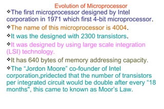
- 1. Evolution of Microprocessor The first microprocessor designed by Intel corporation in 1971 which first 4-bit microprocessor. The name of this microprocessor is 4004. It was the designed with 2300 transistors. It was designed by using large scale integration (LSI) technology. It has 640 bytes of memory addressing capacity. The “Jordon Moore” co-founder of Intel corporation,pridected that the number of transistors per integrated circuit would be double after every “18 months", this came to known as Moor’s Law.
- 2. Evolution of Microprocessor • Intel Microprocessor is divided into following groups. 1. 4-bit Microprocessor-4004. 2. 8-bit Microprocessor-8008,8080,8085. 3. 16-bit Microprocessor-8086,8088,80286. 4. 32-bit Microprocessor- 80386,80486,pentium.pentium pro,pentium- II,pentium-III,pentium-IV
- 3. Evolution of Microprocessor Intel M.processor Year of introducing No. of transistor Initial clock speed Address BUS Data BUS (Word length) Addressabl e Memory Other Companies Processor No of Bit M.processor 4004 1971 2,300 108 KHz 10 Bit 4 Bit 640 bytes Rockwell International PPS-4-bit MP 4-Bit M.processor 8008 1972 3,500 200 KHz 14 Bit 8 Bit 16 Kbytes Zilog’s (Z-80, Z-800) Motorola’s (6800,6809) 8-Bit M.processor 8080 1972 6000 2 MHz 16 Bit 8 Bit 64 Kbytes 8085 1976 6,500 5 MHz 16 Bit 8 Bit 64 Kbytes
- 4. Evolution of Microprocessor Intel M.processor Year of introducing No. of transistor Initial clock speed Address BUS Data BUS (Word length) Addressable Memory Other Companies Processor No of Bit M.processor 8086 1978 29,000 5 MHz 20 Bit 16 Bit 1 MB Zilog’s (Z- 8000) Motorola (68000, 68010) 16-Bit M.processor 8088 1979 29,000 5 MHz 20 Bit 16 Bit /8- bit intern al 1 MB 80286 1982 134,000 8 MHz 24Bit 16 Bit 16 MB
- 5. Evolution of Microprocessor Intel M.processor Year of introducing No. of transistor Initial clock speed Address BUS Data BUS (Word length) Addressable Memory Other Companies Processor No of Bit M.processor 80386 1985 2,75,000 16 MHz 32Bit 32 Bit 4 GB Zilog’s (Z-80000) Motorola (68020, 68030) 32-Bit M.process or 80486 1989 1.2 Million 25 MHz 32 Bit 32 Bit 4 GB Pentium 1993 3.1 Million 60 MHz 32 Bit 32 Bit 4 GB Pentium- Pro 1995 5.5 Million 150 MHz 32 Bit 32 Bit 64 GB
- 6. 8085 Microprocessor Introduction:-The microprocessor is the central processing (CPU) of microcomputer. It is also known heart of computer or Brain of computer. It designed on single chip or IC (Integrated circuit). Microprocessor is also known as programmable digital device, designed with registers, flip-flop and timing element. It is also defined as multipurpose,programmable,clock driven, register based electronic device, that reads the instructions from storage device called memory, accepts the binary data as input & process the data according to instructions & provide the result.
- 7. 8085 Microprocessor • The Intel 8085 is the 8-bit microprocessor developed by Intel corporation in year 1976. • It known as 8-bit Microprocessor because it can process 8-bits at a time. • If the processor consists of more than 8-bits the processor takes up 8-bits of data at first & makes its processing, then next group of data taken up one by one.
- 8. Features of 8085 Microprocessor 1.Intel 8085 is 8 bit microprocessor. 2.It is developed by Intel corporation in 1976. 3.It has 40 pins IC (Integrated circuit ) fabricated on single chip. 4.Its clock speed is 3 to 5 MHz. 5.The Intel 8085 uses a single +5 V D.C. supply for its operation. 6.It is designed by using 6200 to 6500. 7.It has 8-bit data Bus. 8.It has 16 bit address.
- 9. Features of 8085 Microprocessor 9.It has16 bit address lines, therefore it can access 16 2 = 64 Kbytes of memory locations. 10.It has 8-bit I/O Addresses, 8 2 = 256 (0---255) ports can be accessed. 11. It has 80 basic instructions & 246 opcodes. Note : opcode means operational codes every instruction having a code which is stored in memory. MVI A,05 is instruction, the meaning of this instruction is to transfer 05 data in to accumulator. MVI A ,05 ( in coded form 3E,05) where 3E is the opcode of instruction & 05 is 8-bit data)
- 10. Pin Diagram & Description of 8085 Microprocessor VSS AD0-AD7 Vcc X1 X2 A8-A15 RESET IN CLK RESET OUT HOLD IO/M HLDA S0 TRAP S1 RST 7.5 RD RST 6.5 WR RST 5.5 ALE INTR SID SOD INTA READY INTEL 8 0 8 5
- 11. Pin Diagram & Description of 8085 Microprocessor The 8085 microprocessor has 40 pin IC. Pin configuration is as follow. 1.AD0 –AD7 :This is the multiplexed & bidirectional Bus. It is used as address as well as data Bus. The lower 8-bits address (A0—A7) is multiplexed with data Bus (D0—D7). 2.A8- A15 : This is higher order Bus ,higher order addresses (A8-A15) sending through this bus It 8 bit higher order or most significant bits (A8-A15) sending on this bus.
- 12. Pin Diagram & Description of 8085 Microprocessor 3.ALE : (Address latch Enable) Output It is active high signal. It controls the multiplexed bus AD0-AD7. When ALE goes high the Bus AD0-AD7 is used as address Bus i.e. (A0-A7). When ALE goes low the Bus AD0-AD7 is used as data Bus. 4. IO/M (output pin) : It is status signal which distinguishes whether the address is for memory or I/O. When it goes high address on the address bus is for I/O IO/M = High -- Address for I/O IO/M = Low -- Address for Memory
- 13. Pin Diagram & Description of 8085 Microprocessor S0 /S1 (output) :These are status signal sent by the microprocessor to distinguish various types of operation given in table. S1 S0 Operations 0 0 HLT 0 1 WRITE 1 0 READ 1 1 FETCH RD (Output) : This signal is used to control READ operation. When it goes low the memory or I/O device is read. WR ( Output) : This signal is used to control WRITE operation When it goes low data is written into the selected memory or I/O .
- 14. Pin Diagram & Description of 8085 Microprocessor READY (Input): This signal is used by microprocessor to check peripheral is ready to transfer the data or not. A slow peripherals may be connected through this line or pin. HOLD (Input) : Another devices or I/O devices requesting to the processor for the use of data & address Bus. HLDA (Output) : Acknowledgement This is acknowledgement pin . The processor sends acknowledgement (permission) to the requesting device that processor is ready to accept the request.
- 15. Pin Diagram & Description of 8085 Microprocessor INTR (Interrupt) Input : It is an interrupt request signal. INTA (Output): If processor is ready to accept the request then sends acknowledgement signals. Note :Interrupts are signals that cause the computer’s CPU to suspend what is to be doing & transfer to special program called Interrupt handler. When interrupt signal occurs at that time processor stops his main program & transfer towards special programs, the processor executes this subprogram given by interrupt signals & returns towards main program.
- 16. Pin Diagram & Description of 8085 Microprocessor RST 7.5,RST 6.5,RST 5.5 and TRAP : These interrupt signals. Other peripheral devices or co-processors interrupt through this signals or pins. TRAP has highest priority. RESET IN : This is active low signal used to reset microprocessor. When this signal is received by the microprocessor,miroprocessor clears program counter i.e. 0000. RESET OUT (Output): It is active high output signal. It indicates that processor is being reset.
- 17. Pin Diagram & Description of 8085 Microprocessor • X1,X2 (Input) :These are clock input pins connected to crystal oscillator • Which drives an internal circuit of microprocessor to produce suitable clock, for operation of the microprocessor. • CLK (Output): • It is clock output for user can be used for other digital IC’s. • It’s frequency is same at which processor operates. • Internal operating frequency of microprocessor is available on this pin & used to operate other devices in the system with speed.
- 18. Pin Diagram & Description of 8085 Microprocessor • SID & SOD :Serial input data & serial output data • SID pin is used to accept one bit data under software control. • VCC : Vcc provides +5v supply for the operation of microprocessor. • VSS : Ground reference.
- 19. 8085 Microprocessor Architecture or Block diagram of 8085 • The Block diagram of Intel 8085 consists of following three main sections. • 1.Arithematic and Logic unit (ALU) • 2.Timing & control unit • 3.Set of Registers
- 20. 8085 Microprocessor Architecture or Block diagram of 8085 INTR,RST 7.5,RST 6.5,RST 5.5 ,TRAP SID SOD INTA Interrupt control Serial input/output ACCUMULATOR TEMP. REGISTER FLAG REGISTER ALU TIMING & CONTROL INSTRN REGISTER INSTRN DECODER & M/C CYCLE ELCODING ADDRESS BUFFER ADDR./ DATA BUFFER W Z B C D E H L Stack Pointer Prog. Counter Incr./Decre Addr.Latch A15-A8 AD7-AD0
- 21. 8085 Microprocessor Architecture or Block diagram of 8085 • 1.Airtematic & Logic control : (ALU) • ALU is the main part of microprocessor which performs arithmetic & logic operations • Arithmetic operation like addition subtraction. • The logical operations like AND,OR,NOT,Increment,decrement,shift,rotate. • It takes data from accumulator & temporary register & stores the result in accumulator. • ALU is combinational circuit which consists of adder, AND gate, OR gate & NOT gate.
- 22. 8085 Microprocessor Architecture or Block diagram of 8085 • 2.Timing and control Unit :- • The timing & control unit is section of CPU. • It generates timing & control signals which are necessary for the execution of instructions. • It controls data flow between CPU & peripherals (including memory ). • It performs data transfer & decision making operations. • It consists of instruction register, instruction decoder, timing & control circuit. • It control entire operation of microprocessor & peripherals connected to it.
- 23. 8085 Microprocessor Architecture or Block diagram of 8085 • 3.Register Organisation:Resgisters are used by microprocessor for temporary storage of data & instructions. • These registers are known internal memory of M.processor. • The 8085 has following registers :- • 1] One 8-bit accumulator (ACC) or Reg. A • 2] Six 8-bit general purpose registers these are B,C,D,E,H,L. • 3] One 16-bit stack pointer (SP) • 4] One 16-bit program counter (PC) • 5] Instruction register • 6.Temporary Register
- 24. 8085 Microprocessor Architecture or Block diagram of 8085 • 1] One 8-bit accumulator (ACC) or Reg. A :- • Accumulator is 8-bit registers. • It is also known as Reg.A. • It is used to hold one of the operand (data) of an arithmetic & logical operation. • The another operand (Data) for arithmetic & logical operations may stored in memory or one of the register. • It is used as input device to ALU. • Finally result is stored in the accumulator.
- 25. 8085 Microprocessor Architecture or Block diagram of 8085 • 2] General purpose registers :- • The 8085 has 6 general purpose 8 bit registers B,C,D,E,H,L. • These registers available for the user. • These registers used to store 8-bit data. • The pair of two registers can be used as 16-bit registers these pairs are BC,DE,HL.
- 26. 8085 Microprocessor Architecture or Block diagram of 8085 • 3] Stack pointers (SP) :- • It is special purpose register. • It is used to access stack memory. • It always used to point to the stack memory. Note :-Stack Memory : The stack is a sequence of memory locations set aside by programmer to store the contents of accumulator,flags,program counter,& general purpose Reg.during execution of program. • Some part of RAM memory is used as stack. • During the execution of the program some times it becomes necessary to save contents of some registers which are need for some other operations,in subsequent steps of the program. • The contents of such registers saved in the stack.
- 27. 8085 Microprocessor Architecture or Block diagram of 8085 • 4.Program counter : (PC) • Program counter is 16-bit special purpose Register. • It is always used to hold the address of program memory. • It gives the track of memory addresses of the instructions in the program while they are being executed. • It never hold operands or data • It is automatically incremented by control unit during instruction fetch operations. • During instruction fetch operation a 8085 microprocessor places contents of PC on address bus to select appropriate location of program memory.
- 28. 8085 Microprocessor Architecture or Block diagram of 8085 • 5.Instruction Register :- • The instruction register holds the opcode (Operation code or instruction code ) of the instruction which being decoded & executed. • It is 8-bit register. • It is not available for user. • 6] temporary Register :- • It is 8-bit register associated with temporary. • It is not available for user. • It holds data during an arithmetic / Logical Operation • It is used by the microprocessor.
- 29. 8085 Microprocessor Architecture or Block diagram of 8085 • Flag Register :- • It is available for user. • The ALU stores the status of result in the flag registers. • The ALU includes five flip-flops which are set or reset after an operation according to condition of result. • These flag registers are known as flags. • There are five flags of 8085 M.processor. ( carry flag,Auxillary carry flag, parity flag, Zero flag, sign flag ) • These flag registers are connected to ALU.
- 30. 8085 Microprocessor Architecture or Block diagram of 8085 • Flag structure of 8085 or Program status word of 8085 MSB LSB Zero Flag Parity Flag Carry Flag • Sign Flag Auxillary Carry Flag D7 D6 D5 D4 D3 D2 D1 D0 S Z X AC X P X CY
- 31. 8085 Microprocessor Architecture or Block diagram of 8085 • 1] Carry Flag ( CY or CF) :- • After execution of instruction carry is generated ,carry flag set to ‘1’ otherwise reset to ‘0’. • 2] Auxillary carry Flag (AC) :- • If carry is generated from bit 3 to bit 4 (D4-D3) ,it is set to ‘1’ otherwise reset to ‘0’. • 3] Parity Flag (P) :- • If result of operation contains even number of ‘1’ the parity flag is set to’1’ ,or result of operation contains odd no.of ‘1’,the parity flag reset to ‘0’.
- 32. 8085 Microprocessor Architecture or Block diagram of 8085 • 4] Zero Flag :- • If result of operation is zero (0), then zero flag is set to ‘1’ otherwise non zero result reset to ‘0’. • 5] Sign Flag (S) :- • The sign flag ‘S’ set to 1 ,if the result of operation is negative. • It is always used in signed arithmetic operation. • In logical operation MSB is 1 the sign flag is set to1.
- 33. 8085 Microprocessor Architecture or Block diagram of 8085 • Applications of microprocessor :- • 1.Microprocessor are used in controllers, personal computers, low to moderate speed data communication. • 2. microprocessor used as digital controller to control some physical parameters like temperature, pressure. • 3.It is used to control motor speed, traffic light controller, conveyer controls, stepper motor controller. • 4.It is used in data communication application applications including data processing error detection, serial to parallel & parallel to serial data transfers.
- 34. 8085 Microprocessor Architecture or Block diagram of 8085 • 5.It is used in personal computer. • 6.Microprocessor are also used in automobils,applications are ignition control, automatic fuel control. • 7.Microprocessors are used in many medical instruments like X-ray machines,ECG machines. 8.Microprocessors are used in testing & measuring instruments, applications are CRO’s,signal generator power supplies, spectrum analyzers.
- 35. 8085 Microprocessor Architecture or Block diagram of 8085 • Limitations of 8-Bit microprocessor:- • 1.The word length is 8-bit hence processing speed is low. • 2.Due to 16-bit address lines, we can address only up to 64 Kbytes of memory. • 3.8-bit microprocessor has multiplexed address & data bus, so extra hardware is required to separate address signals. • 4.It can read one instruction at a time ,unless first instruction gets executed completely, microprocessor can not read second instruction from memory as it has only one instruction register. • 5.Operating speed is less so the speed of execution is low.
- 36. 8085 Microprocessor Architecture or Block diagram of 8085 • 6.Using 8-bit microprocessor, we can not design multiprocessor system. • 7. Due to limited size of the all register, we can store limited data bytes in the microprocessor memory. • 8.There is no memory management unit. • 9. It is used for control applications. • 10. It is not used in work stations & servers.
- 37. 8085 Microprocessor Architecture or Block diagram of 8085