
Recommended
More Related Content
Similar to Version 1.0Pocket Campus TourArchitectureDesign Document.docx
Similar to Version 1.0Pocket Campus TourArchitectureDesign Document.docx (20)
More from jessiehampson
More from jessiehampson (20)
Recently uploaded
Recently uploaded (20)
Version 1.0Pocket Campus TourArchitectureDesign Document.docx
- 1. Version: 1.0 Pocket Campus Tour Architecture/Design Document Table of Contents 31Introduction 42Design Goals 43System Behavior 54Logical View 54.1High-Level Design (Architecture) 64.2Mid-Level Design 84.3Detailed Class Design 115Process View 126Development View 127Physical View 128Use Case View Change History Version: 0.3 Modifier: Eddie Burris Date: 4/5/2006 Description of Change: Added sequence diagrams for self- directed mode. _____________________________________________________ _ Version: 0.2
- 2. Modifier: Eddie Burris Date: 3/20/2006 Description of Change: Added process view and use case view. Also added sequence diagram to logical view. _____________________________________________________ _ Version: 0.1 Modifier: Eddie Burris Date: 3/15/2006 Description of Change: Initial rough draft. Contains logical view (high-level modules only) and development view. _____________________________________________________ _ 1 Introduction This document describes the architecture and design for the Pocket Campus Tour application being developed for the University of Missouri—Kansas City (UMKC). Pocket Campus Tour is a PDA application that turns a GPS enabled PDA into a personal tour guide providing audio commentary on the buildings and notable structures on the UMKC campus. Pocket Campus Tour has a roaming mode that requires zero computer skills. Visitors simply carry the device with them as they stroll the campus and it provides audio commentary relevant to the visitor’s current location. For those who can’t or don’t want to stroll the campus, the application also offers a self-directed mode where the same position-dependent audio commentary is available from an interactive onscreen campus map.
- 3. The purpose of this document is to describe the architecture and design of the Pocket Campus Tour application in a way that addresses the interests and concerns of all major stakeholders. For this application the major stakeholders are: · Users and the customer – they want assurances that the architecture will provide for system functionality and exhibit desirable non-functional quality requirements such as usability, reliability, etc. · Developers – they want an architecture that will minimize complexity and development effort. · Project Manager – the project manager is responsible for assigning tasks and coordinating development work. He or she wants an architecture that divides the system into components of roughly equal size and complexity that can be developed simultaneously with minimal dependencies. For this to happen, the modules need well-defined interfaces. Also, because most individuals specialize in a particular skill or technology, modules should be designed around specific expertise. For example, all UI logic might be encapsulated in one module. Another might have all logic related to GPS coordinates. · Maintenance Programmers – they want assurance that the system will be easy to evolve and maintain on into the future. The architecture and design for a software system is complex and individual stakeholders often have specialized interests. There is no one diagram or model that can easily express a system’s architecture and design. For this reason, software architecture and design is often presented in terms of multiple views or perspectives [IEEE Std. 1471]. Here the architecture of the Pocket Campus Tour application is described from 4 different perspectives [1995 Krutchen]:
- 4. 1. Logical View – major components, their attributes and operations. This view also includes relationships between components and their interactions. When doing OO design, class diagrams and sequence diagrams are often used to express the logical view. 2. Process View – the threads of control and processes used to execute the operations identified in the logical view. 3. Development View – how system modules map to development organization. 4. Use Case View – the use case view is used to both motivate and validate design activity. At the start of design the requirements define the functional objectives for the design. Use cases are also used to validate suggested designs. It should be possible to walk through a use case scenario and follow the interaction between high-level components. The components should have all the necessary behavior to conceptually execute a use case. 2 Design Goals There is no absolute measure for distinguishing between good and bad design. The value of a design depends on stakeholder priorities. For example, depending on the circumstances, an efficient design might be better than a maintainable one, or vise versa. Therefore, before presenting a design it is good practice to state the design priorities. The design that is offered will be judged according to how well it satisfies the stated priorities. The priorities for the design that follows are: · The design should minimize complexity and development effort.
- 5. · The design should take into account the development environment which is 6-7 small teams with complementary skills that work across time and space (teams are not co- located). Ideally the design should result in 6-7 loosely coupled components of equal size and complexity. If the components have well-defined interfaces each team can work independently coding to the interfaces of the other components. The concerns of each component should be narrow so that each team can specialize on a particular technology or skill. · The design shouldn’t inhibit reusability. The two previous design goals are more important, but the ability to reuse components is also desirable. 3 System Behavior The use case view is used to both drive the design phase and validate the output of the design phase. The architecture description presented here starts with a review of the expect system behavior in order to set the stage for the architecture description that follows. For a more detailed account of software requirements, see the requirements document. Figure 1 System Behavior 4 Logical View The logical view describes the main functional components of the system. This includes modules, the static relationships between modules, and their dynamic patterns of interaction. In this section the modules of the system are first expressed in terms of high level components (architecture) and progressively refined into more detailed components and eventually classes with specific attributes and operations. 4.1 High-Level Design (Architecture)
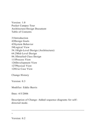
- 6. The high-level view or architecture consists of 5 major components: Figure 2 System Architecture · The GPS device provides the user’s location on campus (longitude and latitude coordinates). In basic mode, the user’s position is used to decide which buildings to announce. · The Database is a central repository for data on buildings, their locations and associated audio segments. · The Audio Player controls playback of audio files. · Given a position on earth, the Mapping Logic will calculate nearby buildings. · The Application Control Logic is the main driver of the application. It presents information to the user and reacts to user inputs. 4.2 Mid-Level Design Figure 3 Mid-Level design components and their relationships Figure 4 shows the dynamic behavior of mid-level components in basic mode. Figure 4 Basic Mode Sequence Diagram Figure 5 shows the dynamic behavior of mid-level components in self-directed mode. Figure 5 Self-Directed mode sequence diagram 4.3 Detailed Class Design
- 7. 5 Process View Each loop represents a thread of control. 6 Development View 7 Physical View [TBD] 8 Use Case View (The following is more algorithm than use-case view. Fix later.) Basic Tour: 1. Get instance of GPS Device. 2. Start GPS Device. 3. Register as a listener for events: OnConnectionObtained, OnConnectionLost, and PositionChanged. 4. Display welcome message on screen. Play welcome audio. 5. While (! Interrupted) do looking(); if (connected and !interrupted) do map(); looking() 1. if (connected) return;
- 8. 2. Display “Looking for satellites …” 3. Play associated audio. 4. Play one minute of soothing music. (interruptible) 5. while (! Connected and ! Interrupted) Play one minute of soothing music. (interruptible) Play “still looking” map() 1. Ask CampusData for small map 2. Create and display CampusImage 3. Center the image on the display so user’s location is at the center 4. While (connected and !interrupted) get current position from GPSDevice get building near current position pick one play audio data for selected building OnConnectionObtained play 1 second of silence to stop current audio OnConnectionLost connected = false OnPositionChanged center image around new position Welcome
- 10. “Searching for satellites …” Mode “Welcome to basic mode. In basic mode …” Application Basic Mode Audio Player Mapping Logic Database GUI Thread
- 11. GPS Device Self-Dir Mode * *Self-Directed mode will create a temporary thread to play audio after a screen click event. [TBD: redraw class diagram using uml 2.0 active class notation.] Page 2 of 12 Version: 1.0 [Project Name] Architecture/Design Document Table of Contents 31Introduction 42Design Goals 43System Behavior 54Logical View 54.1High-Level Design (Architecture) 64.2Mid-Level Design 84.3Detailed Class Design
- 12. 115Process View 126Development View 127Physical View 128Use Case View Change History Version: <x.y> Modifier: <Name> Date: mm/dd/yyyy Description of Change: <What was modified/added?> _____________________________________________________ _ Version: <x.y> Modifier: <Name> Date: mm/dd/yyyy Description of Change: <What was modified/added?> 1 Introduction Architecture and Design The purpose of the architecture/design document is to explain the organization of the code. A well-written architecture document will make it easier for new programmers to become familiar with the code. The architecture/design document should identify major system components and describe their static attributes and dynamic
- 13. patterns of interaction. Software architecture and designs are typically expressed with a mix of UML models (class and sequence diagrams being the two most common) and prose. Dataflow diagrams are also helpful for understanding the interaction between components and overall flow of data through the system. About this Template This template suggests one way of documenting a software system’s architecture/design. You aren’t required to include every section in this template nor all the content in the sections you do include. However, the document you do submit should pass the following checklist: · Are design objectives clearly stated? For example, if performance is more important than reusability, this should be made clear at the start of the design specification. · Does the architecture partition the implementation into clearly defined subsystems or modules with well-defined interfaces? · Does the architecture express in a clear way the main patterns of communication between subsystems and modules? · Does the architecture satisfy the requirements? · Is the architecture traceable to requirements? · Any models created should either be expressed with a well- known modeling language, or if a well-known modeling language isn't used, the syntax and semantics of the symbols that are used should be defined. This document describes the architecture and design for the
- 14. <product name> application being developed for <customer>. <brief description of what the software does>. The purpose of this document is to describe the architecture and design of the <product name> application in a way that addresses the interests and concerns of all major stakeholders. For this application the major stakeholders are: · Users and the customer – they want assurances that the architecture will provide for system functionality and exhibit desirable non-functional quality requirements such as usability, reliability, etc. · Developers – they want an architecture that will minimize complexity and development effort. · Project Manager – the project manager is responsible for assigning tasks and coordinating development work. He or she wants an architecture that divides the system into components of roughly equal size and complexity that can be developed simultaneously with minimal dependencies. For this to happen, the modules need well-defined interfaces. Also, because most individuals specialize in a particular skill or technology, modules should be designed around specific expertise. For example, all UI logic might be encapsulated in one module. Another might have all business logic. · Maintenance Programmers – they want assurance that the system will be easy to evolve and maintain on into the future. The architecture and design for a software system is complex and individual stakeholders often have specialized interests. There is no one diagram or model that can easily express a system’s architecture and design. For this reason, software architecture and design is often presented in terms of multiple views or perspectives [IEEE Std. 1471]. Here the architecture of
- 15. the <product name> application is described from 4 different perspectives [1995 Krutchen]: 1. Logical View – major components, their attributes and operations. This view also includes relationships between components and their interactions. When doing OO design, class diagrams and sequence diagrams are often used to express the logical view. 2. Process View – the threads of control and processes used to execute the operations identified in the logical view. 3. Development View – how system modules map to development organization. 4. Use Case View – the use case view is used to both motivate and validate design activity. At the start of design the requirements define the functional objectives for the design. Use cases are also used to validate suggested designs. It should be possible to walk through a use case scenario and follow the interaction between high-level components. The components should have all the necessary behavior to conceptually execute a use case. 2 Design Goals There is no absolute measure for distinguishing between good and bad design. The value of a design depends on stakeholder priorities. For example, depending on the circumstances, an efficient design might be better than a maintainable one, or vise versa. Therefore, before presenting a design it is good practice to state the design priorities. The design that is offered will be judged according to how well it satisfies the stated priorities. The design priorities for the <product name> application are: · The design should minimize complexity and development
- 16. effort. · The design should <another design goal>. 3 System Behavior The use case view is used to both drive the design phase and validate the output of the design phase. The architecture description presented here starts with a review of the expect system behavior in order to set the stage for the architecture description that follows. For a more detailed account of software requirements, see the requirements document. <brief description of system behavior> 4 Logical View The logical view describes the main functional components of the system. This includes modules, the static relationships between modules, and their dynamic patterns of interaction. In this section the modules of the system are first expressed in terms of high level components (architecture) and progressively refined into more detailed components and eventually classes with specific attributes and operations. 4.1 High-Level Design (Architecture) The high-level view or architecture consists of <?> major components: <list and/or show major architecture components> Example: System Architecture · The GPS device provides the user’s location on campus (longitude and latitude coordinates). In basic mode, the user’s
- 17. position is used to decide which buildings to announce. · The Database is a central repository for data on buildings, their locations and associated audio segments. · The Audio Player controls playback of audio files. · Given a position on earth, the Mapping Logic will calculate nearby buildings. · The Application Control Logic is the main driver of the application. It presents information to the user and reacts to user inputs. 4.2 Mid-Level Design <Explain and/or show static and dynamic aspects of subsystem components. Probably the most effective way of showing mid- level design is with class and sequence diagrams.> 4.3 Detailed Class Design <For a few key classes you might want to show associations, attributes and methods.> 5 Process View <Where are the threads of control in the application?>6 Physical View <Where will major components be physically deployed?> 7 Use Case View <Sketch architecturally significant use cases.>
- 19. Page 6 of 6 Campus Connect Team B Architecture Document Campus Connect Team B – Winter 2007
- 20. Table of Contents 1.0 Introduction………………………………………………………… …… 2 2.0 High Level Hierarchy…………………………………………………… 2 2.1 Hierarchy Diagram……………………………………………… 2 2.2 Hierarchy Description…………………………………………... 2 3.0 Components Classification……………………………………………… 3 3.1 Presentation Layer………………………………………………. 3 3.2 Controller Layer…………………………………………………. 4 3.3 Business Layer…………………………………………………... 4
- 21. 3.4 Record Layer…………………………………………………….. 5 3.5 Data Access Layer……………………………………………….. 6 3.6 Database Layer…………………………………………………… 7 4.0 Process View……………………………………………………………... 8 4.1 Description……………………………………………………….. 8 4.2 Application Thread………………………………………………. 8 4.3 Presentation Thread……………………………………………… 8 4.4 Connection Thread……………………………………………….. 9
- 22. 4.5 GPS Thread………………………………………………………. 9 4.6 Device Thread……………………………………………………. 9 1.0 Introduction The Campus Connect Team B (CCB) Architecture Document is designed to illustrate and identify the high level architecture systems used to design and implement the Campus Connect application. The document contains an overall view of the system hierarchy, logical views of the system components, and a process view of the system’s communication. 2.0 High Level Hierarchy 2.1 Hierarchy Diagram 2.2 Hierarchy Description The architecture system for the CCB application is an n-tier architecture. This architecture system is designed to allow for proper information hiding, modular components, and single system dependencies. The abstraction of the presentation layer, and consequently the User Interface (UI), allow for a flexible pipeline for the optimization of the UI to meet customer needs and expectations. There are multiple layers between the Presentation Layer and the lowest level, due to the significant challenges present in the optimization and control of the Processes design. The Database layer is the lowest level in the hierarchy, and is an abstraction used to represent both text data
- 23. (in the form of XML files), and serial device data. 3.0 Components Classification 3.1 Presentation Layer Purpose: To display forms, controls, images and sounds to the user to create a fluid and efficient user experience. Specific Nature: The presentation layer will be in charge of displaying appropriate images, menus, and sounds to the user. This layer will also be in charge of handling stylus clicks. When a user clicks a menu on the GUI, the code corresponding to that event will be called. This layer will also be in charge of the spawning of appropriate threads. The need of spawning extra threads is due to the fact that the main thread of the app will be watching for event clicks, but we also need another thread constantly running to get the users current position. Subcomponents: Image Viewer, Audio Player, Current State Current State – The Current State will be a global class that will get updated by the Presentation Thread. The Current State class will be read from the main thread of the app at a specified time interval as governed by a timer. The Current State class will have the following design: · Current State · Landmark – Holds the current closest landmark. Will be of type Landmark Record class. · User – Holds the current User position. Will be of type User Record class. · Sound – Descriptor for the current sound or music to be played.
- 24. The Current State must be synchronized. This is due to the idea of thread safety. We do not want the main thread to read the Current State class while the Presentation Thread updates the Current State class. The synchronized keyword basically puts a lock on the Current State class while a thread is using it. Image Viewer – The Image Viewer subcomponent is used during the Walking Tour and during the Interactive Map mode of the application. Its responsibility is to display the appropriate image as determined by the Landmark held in the Current State. Audio Player – The Audio Player subcomponent is responsible for playing the proper sound effect/music/description as determined by the Current State. The Audio Player must be able to load and play .Wav files, as well as be able to pause and stop. Pending functionality is a fade-in transition. 3.2 Controller Layer Purpose: Processes and responds to events, typically user actions, and may invoke changes on the model. Specific Nature: The controller layer in our program will be in charge of getting the closest landmark to the current user position. It will do this on a constant interval of k. k is a 5-10 second time step that will be determined through testing. This layer populates the closest landmark based off of user input. In this case, user input is the user walking around. This will notify the presentation layer when the closest landmark has been updated. Associated Constructs: Landmark Controller · Landmark Controller – Landmark Controller class will consist of the closest current Landmark according to user position. This class will be updated with the new closest Landmark every k
- 25. seconds. This Landmark Controller will be executed by the Presentation Thread while the user is taking the Walking Tour. · Landmark Controller · Current Closest Landmark – Holds the current closest landmark. Will be of type Landmark Record class. 3.3 Business Layer Purpose: This layer is in charge of the heavy algorithm business logic found in complex solutions. Specific Nature: This layer will be used to compute the algorithm for finding the user’s current position and the closest landmark. The closest landmark algorithm will be located in a class called Landmark Manager. The user location algorithm will be located in a class called User Manager. This layer will also contain a class called Error Manager. This class is in charge of getting the appropriate error message based on the actions of the user. Associated Constructs: Landmark Manager, User Manager, Error Manager · Landmark Manager – Landmark Manager class will consist of a method to find the closest landmark according to the current user position. · Landmark Manager · Get Closet Landmark() – Will compute the closest landmark according to user position. Returns a Landmark Record data type. · User Manager – User Manager class will consist of a method to find the current user position. · User Manager · Get Current User Position() – Will compute the current user position. Will return a User Record data type. · Error Manager – Error Manager class will consist of a method to find the current error.
- 26. · Error Manager · Get Error() – Will return the current error depending on the actions of the user. Will return an Error Record data type. 3.4 Record Layer Purpose: This layer is in charge of containing the classes that strictly consist of data. Little to no functional methods will be found in these classes. Specific Nature: This layer will be used to store User data, Landmark data, and Error data and Location data. These classes will only contain properties (variables) that describe each data type. Associated Constructs: User Record, Landmark Record, Error Record · User Record – User Record class will consist of only properties describing a user. This class will be static, meaning there is only one copy of this class in memory once initialized until the end of the program. This will be static because of the ease of dynamically updating the latitude and longitude of only one static user in memory. · User Record · User Type – Will hold the type of user that is using the device. Possible values are: Technical and Non-Technical. A TechnicalUser Type signifies the user will be navigating the device with a stylus and menus. A Non-Technical user will signify that the user will be only walking around the campus, without the use of menus and the stylus. This property is of type string. · Current Lat - This will hold the current latitude of the user. This will be of type string. · Current Long - This will hold the current longitude of the user. This will be of type string. · Landmark Record – Landmark Record class will consist of
- 27. only properties describing a Landmark. · Landmark Record · Name – Will hold the name of the landmark. This property is of type string. · Latitude – Will hold the latitude of the landmark. This property is of type string. · Longitude – Will hold the longitude of the landmark. This property is of type string. · Description – Will hold the description of the landmark. This property is of type string. · Image Source – Will hold the local path of the landmark’s image. This property is of type string. · Sound Source – Will hold the local path of the landmark’s sound description. This property is of type string. · Error Record – Error Record class will consist of only properties describing an error. · Error Record · Name – Will hold the name of the error. This property is of type string. · Description – Will hold the description of the error. This property is of type string. 3.5 Data Access Layer Purpose: This layer is in charge of communicating to the database. This layer should handle all of the database transactions and connectivity. Specific Nature: This layer will be in charge of communication to our database which will in turn lead to populating the record layer. Our database in this project will consist of XML files and serial device data from GPS satellites. The GPSDAL class will be used to strictly communicate to the external GPS satellites and return current latitude and longitude coordinates of the user. The Landmark DAL class will be used to read the Landmarks XML file and populate Landmark Record classes based on the data in the Landmarks XML file. The User DAL
- 28. class will be used to initialize a User Record class. This User DAL class will only be in charge of initializing the User Record class to null because we will not be storing different user types in an XML file. The Error DAL class will be in charge of reading an Error XML file and populating all of the Error Record classes according to all of the different types of errors the system can throw. Associated Constructs: Landmark DAL, User DAL, Error DAL · Landmark DAL – Landmark DAL class will be used to read the Landmarks XML file and populate Landmark Record classes based on the data in the Landmarks XML file. · Landmark DAL · Get Landmark() – This method will read in a Landmarks XML file and populate a Landmark Record class. This return type is of type Landmark Record. · User DAL – User DAL class will be used to initialize a User Record class to null. · User DAL · Get User() – This method will return an initialized User Record. · Error DAL – Error DAL class will be used to read the Errors XML file and populate Error Record classes based on the data in the Errors XML file. · Error DAL Get Error() – This method will read in an Errors XML file and populate an Error Record class. This return type is of type Error Record. 3.6 Database Layer Purpose: This layer is in charge of storing data in persistent storage. Specific Nature: This layer will consist of XML files. These
- 29. together will be our database management system. These XML files will store Landmarks, Errors, and eventually Language Support. Serial device data received from the embedded GPS device will also be considered part of the abstract database layer. Associated Constructs: Landmarks XML, Errors XML, GPS Interface · Landmarks XML – Landmarks XML will be used to store all Landmarks that will be supported in our system. · Landmarks XML <campus> <building> <name>Flarsheim Hall</name> <lati>39.020119</lati> <long>94.343871</long> <descrip>blank</descrip> <img>Resources//fh.jpg</img> <snd>Resources//fh.wav</snd> </building> </campus>
- 30. · Errors XML – Errors XML will be used to store all Errors that could be used in our system. *design is currently incomplete · GPS Interface – This module is the direct interface between the database layer and the available Mobile 5.0 methods provided for the embedded GPS device. · Get Longitude( ) & Get Latitude( ) methods are used to obtain the current location of the device once an event is fired by the GPS Thread. 4.0 Process View 4.1 Process View Description The Process View is essential in understanding how the separate components and subcomponents communicate with each other in a concurrent application. By better understanding the necessary paths of communication between the components, it may be possible to optimize the data flow and storage of the application, as well as ensuring thread-safety. 4.2 Application Thread This thread is the main application thread that is created at runtime of the program. The program creates the thread; this is not a user created thread. This thread handles the basic program flow by controlling navigation between forms, and processing window events, including the handling of user input to the graphical forms. 4.3 Presentation Thread This thread is user created, when the application enters the Walking Tour mode. This thread is responsible for seeking the nearest landmark and then relaying this information to the Presentation Layer, where this thread requests that Image Viewer and Audio Player subcomponents update the current
- 31. presentation when necessary. 4.4 Connection Thread This thread is user created. This thread is in charge of always checking if the connection to the GPS device is valid and working. Before we switch between certain forms in our application, we will be checking this connection thread to ensure that the connection is valid before proceeding. This thread is also in charge of keeping track of the seconds of time that the connection has been invalid. If the connection has been invalid for a certain time of k seconds, we will notify the user and try to re-connect. If the connection has been invalid for less than a certain time of k seconds, we will continue with our program flow without notifying the user that the connection has failed while attempting to reestablish the connection. 4.5 GPS Thread This thread is user created. This thread will always be reading the current user latitude and longitude from the GPS device. This thread will be providing our program with all of the necessary information about user position, and will be updated every time the user changes position. The connection thread will be constantly checking with this thread for a valid connection. 4.6 Device Thread This thread is user created. This thread will always be reading the current state of the device. This thread will keep track of the device state and if the device state has changed, it will fire off an event notifying the change of the device state, thus resulting in the GPS thread updating the current position. The Connection thread does not communicate directly with this thread.
- 32. . Paper published in IEEE Software 12 (6) November 1995, pp. 42-50 Architectural Blueprints—The “4+1” View Model of Software Architecture Philippe Kruchten Rational Software Corp. Abstract This article presents a model for describing the architecture of software-intensive systems, based on the use of multiple, concurrent views. This use of multiple views allows to address separately the concerns of the various ‘stakeholders’ of the architecture: end-user, developers, systems engineers, project managers, etc., and to handle separately the functional and non functional requirements. Each of the five views is described, together with a notation to capture it. The views are designed using an architecture-centered, scenario- driven, iterative development process. Keywords: software architecture, view, object-oriented design, software development process Introduction We all have seen many books and articles where one diagram attempts to capture the gist of the architecture of a system. But looking carefully at the set of boxes and arrows shown on these diagrams, it becomes clear that their authors have struggled hard to represent more on one blueprint than it can actually express. Are
- 33. the boxes representing running programs? Or chunks of source code? Or physical computers? Or merely logical groupings of functionality? Are the arrows representing compilation dependencies? Or control flows? Or data flows? Usually it is a bit of everything. Does an architecture need a single architectural style? Sometimes the architecture of the software suffers scars from a system design that went too far into prematurely partitioning the software, or from an over-emphasis on one aspect of software development: data engineering, or run-time efficiency, or development strategy and team organization. Often also the architecture does not address the concerns of all its “customers” (or “stakeholders” as they are called at USC). This problem has been noted by several authors: Garlan & Shaw1, Abowd & Allen at CMU, Clements at the SEI. As a remedy, we propose to organize the description of a software architecture using several concurrent views, each one addressing one specific set of concerns. An Architectural Model Software architecture deals with the design and implementation of the high-level structure of the software. It is the result of assembling a certain number of architectural elements in some well-chosen forms to satisfy the major functionality and performance requirements of the system, as well as some other, non-functional requirements such as reliability, scalability, portability, and availability. Perry and Wolfe put it very nicely in this formula2, modified by Boehm: Software architecture = {Elements, Forms, Rationale/Constraints} Software architecture deals with abstraction, with
- 34. decomposition and composition, with style and esthetics. To describe a software architecture, we use a model composed of multiple views or perspectives. In order to eventually address large and challenging architectures, the model we propose is made up of five main views (cf. fig. 1): • The logical view, which is the object model of the design (when an object-oriented design method is used), • the process view, which captures the concurrency and synchronization aspects of the design, • the physical view, which describes the mapping(s) of the software onto the hardware and reflects its distributed aspect, 2 • the development view, which describes the static organization of the software in its development environment. The description of an architecture—the decisions made—can be organized around these four views, and then illustrated by a few selected use cases, or scenarios which become a fifth view. The architecture is in fact partially evolved from these scenarios as we will see later. Logical View Development View Process View Physical View Scenarios
- 35. Programmers Software management System engineers Topology Communications Integrators Performance Scalability End-user Functionality Figure 1 — The “4+1” view model We apply Perry & Wolf’s equation independently on each view, i.e., for each view we define the set of elements to use (components, containers, and connectors) , we capture the forms and patterns that work, and we capture the rationale and constraints, connecting the architecture to some of the requirements. Each view is described by a blueprint using its own particular notation. For each view also, the architects can pick a certain architectural style, hence allowing the coexistence of multiple styles in one system. We will now look in turn at each of the five views, giving for each its purpose: which concerns is addresses, a notation for the corresponding architectural blueprint, the tools we have used to describe and manage it. Small examples are drawn from the design of a PABX, derived from our work at Alcatel Business System and an Air Traffic Control system3, but in very simplified
- 36. form—the intent here is just to give a flavor of the views and their notation and not to define the architecture of those systems. The “4+1” view model is rather “generic”: other notations and tools can be used, other design methods can be used, especially for the and the logical and process decompositions, but we have indicated the ones we have used with success. 3 The Logical Architecture The Object-Oriented Decomposition The logical architecture primarily supports the functional requirements—what the system should provide in terms of services to its users. The system is decomposed into a set of key abstractions, taken (mostly) from the problem domain, in the form of objects or object classes. They exploit the principles of abstraction, encapsulation, and inheritance. This decomposition is not only for the sake of functional analysis, but also serves to identify common mechanisms and design elements across the various parts of the system. We use the Rational/Booch approach for representing the logical architecture, by means of class diagrams and class templates.4 A class diagram shows a set of classes and their logical relationships: association, usage, composition, inheritance, and so forth. Sets of related classes can be grouped into class categories. Class templates focus on each individual class; they emphasize the main class operations, and identify key object characteristics. If it is important to define the internal behavior of an object, this is done with state transition
- 37. diagrams, or state charts. Common mechanisms or services are defined in class utilities. Alternatively to an OO approach, an application that is very data-driven may use some other form of logical view, such as E-R diagrams. Notation for the logical view The notation for the logical view is derived from the Booch notation4. It is considerably simplified to take into account only the items that are architecturally significant. In particular, the numerous adornments are not very useful at this level of design. We use Rational Rose® to support the logical architecture design. Components Class Parameterized Class Class Utility Class category Association Containment, Aggregation Usage Inheritance Instanciation
- 38. Connectors Figure 2 — Notation for the logical blueprint Style for the logical view The style we use for the logical view is an object-oriented style. The main guideline for the design of the logical view is to try to keep a single, coherent object model across the whole system, to avoid premature specialization of classes and mechanisms per site or per processor. 4 Examples of Logical blueprints Figure 3a shows the main classes involved in the Télic PABX architecture. Conversation Terminal Controller Numbering Plan Connection Services Translation Services Simulation and Training
- 39. Flight management Air Traffic Management External Interfaces -Gateways Aeronautical Information Basic elements Mechanisms Services Display & User Interface Figure 3— a. Logical blueprint for the Télic PABX . b. Blueprint for an Air Traffic Control System A PABX establishes commmunications between terminals. A terminal may be a telephone set, a trunk line (i.e., line to central-office), a tie line (i.e., private PABX to PABX line), a feature phone line, a data line, an ISDN line, etc. Different lines are supported by different line interface cards. The responsibility of a line controller object is to decode and inject all the signals on the line interface card, translating card-specific
- 40. signals to and from a small, uniform set of events: start, stop, digit, etc. The controller also bears all the hard real-time constraints. This class has many subclasses to cater for different kinds of interfaces. The responsibility of the terminal object is to maintain the state of a terminal, and negotiate services on behalf of that line. For example, it uses the services of the numbering plan to interpret the dialing in the selection phase. The conversation represents a set of terminals engaged in a conversation. The conversation uses translation services (directory, logical to physical address mapping, routes), and connection services to establish a voice path between the terminals. For a much bigger system, which contains a few dozen classes of architectural significance, figure 3b show the top level class diagram of an air traffic control system, containing 8 class categories (i.e., groups of classes). The Process Architecture The Process Decomposition The process architecture takes into account some non-functional requirements, such as performance and availability. It addresses issues of concurrency and distribution, of system’s integrity, of fault-tolerance, and how the main abstractions from the logical view fit within the process architecture—on which thread of control is an operation for an object actually executed. The process architecture can be described at several levels of abstraction, each level addressing different concerns. At the highest level, the process architecture can be viewed as a set of independently executing logical networks of communicating programs (called “processes”), distributed across a set of hardware resources connected by a LAN or a WAN. Multiple logical networks may exist simultaneously, sharing the
- 41. same physical resources. For example, independent logical networks may be used to support separation of the on-line operational system from the off-line system, as well as supporting the coexistence of simulation or test versions of the software. A process is a grouping of tasks that form an executable unit. Processes represent the level at which the process architecture can be tactically controlled (i.e., started, recovered, reconfigured, and shut down). In 5 addition, processes can be replicated for increased distribution of the processing load, or for improved availability. The software is partitioned into a set of independent tasks. A task is a separate thread of control, that can be scheduled individually on one processing node. We can distinguish then: major tasks, that are the architectural elements that can be uniquely addressed and minor tasks, that are additional tasks introduced locally for implementation reasons (cyclical activities, buffering, time-outs, etc.). They can be implemented as Ada tasks for example, or light-weight threads. Major tasks communicate via a set of well-defined inter-task communication mechanisms: synchronous and asynchronous message-based communication services, remote procedure calls, event broadcast, etc. Minor tasks may communicate by rendezvous or shared memory. Major tasks shall not make assumptions about their collocation in the same process or processing node. Flow of messages, process loads can be estimated based on the process blueprint. It is also possible to implement a “hollow” process architecture with dummy loads
- 42. for the processes, and measure its performance on the target system, as described by Filarey et al. in their Eurocontrol experiment. Notation for the Process view The notation we use for the process view is expanded from the notation originally proposed by Booch for Ada tasking. Again the notation used focuses on the elements that are architecturally significant. (Fig. 4) Message Remote Procedure Call Message, bidirectional Event broadcast Periodic process adornment Process Unspecified ConnectorsComponents Simplified Process (Indicates a cyclical process) Figure 4 — Notation for the Process blueprint
- 43. We have used the Universal Network Architecture Services (UNAS) product from TRW to architect and implement the set of processes and tasks (and their redundancies) into networks of processes. UNAS contains a tool—the Software Architects Lifecycle Environment (SALE)—which supports such a notation. SALE allows for the graphical depiction of the process architecture, including specifications of the possible inter-task communication paths, from which the corresponding Ada or C++ source code is automatically generated. The benefit of this approach to specifying and implementing the process architecture is that changes can be incorporated easily without much impact on the application software. Style for the process view Several styles would fit the process view. For example, picking from Garlan and Shaw’s taxonomy1 we can have: pipes and filters, or client/server, with variants of multiple client/single server and multiple clients/multiple servers. For more complex systems, one could use a style similar to the process groups approach of the ISIS system as described by K. Birman with another notation and toolset. 6 Example of a Process blueprint Controller task Low rate
- 44. Controller task High rate Main controller task Controller process Terminal process Figure 5 — Process blueprint for the Télic PABX (partial) All terminals are handled by a single terminal process, which is driven by messages in its input queues. The controller objects are executed on one of three tasks that composes the controller process: a low cycle rate task scans all inactive terminals (200 ms), puts any terminal becoming active in the scan list of the high cycle rate task (10ms), which detects any significant change of state, and passes them to the main controller task which interprets the changes and communicates them by message to the corresponding terminal. Here message passing within the controller process is done via shared memory. The Development Architecture Subsystem decomposition The development architecture focuses on the actual software module organization on the software development environment. The software is packaged in small chunks—program libraries, or subsystems— that can be developed by one or a small number of developers. The subsystems are organized in a hierarchy
- 45. of layers, each layer providing a narrow and well-defined interface to the layers above it. The development architecture of the system is represented by module and subsystem diagrams, showing the ‘export’ and ‘import’ relationships. The complete development architecture can only be described when all the elements of the software have been identified. It is, however, possible to list the rules that govern the development architecture: partitioning, grouping, visibility. For the most part, the development architecture takes into account internal requirements related to the ease of development, software management, reuse or commonality, and to the constraints imposed by the toolset, or the programming language. The development view serves as the basis for requirement allocation, for allocation of work to teams (or even for team organization), for cost evaluation and planning, for monitoring the progress of the project, for reasoning about software reuse, portability and security. It is the basis for establishing a line-of-product. Notation for the Development Blueprint Again, a variation of the Booch notation, limiting it to the items that are architecturally significant. 7 Reference Compilation dependency (include, "with") Module Subsystem
- 46. ConnectorsComponents Layer Figure 5 — Notation for the Development blueprint The Apex Development Environment from Rational supports the definition and the implementation of the development architecture, the layering strategy described above, and the enforcement of the design rules. Rational Rose can draw the development blueprints at the module and subsystem level, in forward engineering and by reverse engineering from the development source code, for Ada and C++. Style for the Development View We recommend adopting a layered style for the development view, defining some 4 to 6 layers of subsystems. Each layer has a well-defined responsibility. The design rule is that a subsystem in a certain can only depend on subsystem that are in the same layer or in layers below, in order to minimize the development of very complex networks of dependencies between modules and allow simple release strategies layer by layer. Common utilities Bindings Low-level services Support Mechanisms: Communication, Time, Storage, Resource management, etc. Aeronautical classes ATC classes
- 47. ATC Functional areas: Flight manag- ement, Sector Management, etc. Man-Machine Interface External systems Off-line tools Test harnesses HardWare, OS, COTS Basic elements Distributed Virtual Machine ATC Framework HATS Components CAATS, MAATS, etc... 5 1 2 3 4 Figure 6 — The 5 layers of Hughes Air Traffic Systems (HATS) Example of Development architecture Figure 6 represents the development organization in five layers of a line-of-product of Air Traffic Control systems developed by Hughes Aircraft of Canada3. This is the development architecture corresponding to
- 48. the logical architecture shown in fig. 3b. Layers 1 and 2 constitute a domain-independent distributed infrastructure that is common across the line of products and shields it from variations in hardware platform, operating system, or off-the-shelf products 8 such as database management system. To this infrastructure, layer 3 adds an ATC framework to form a domain-specific software architecture. Using this framework a palette of functionality is build in layer 4. Layer 5 is very customer- and product-dependent, and contains most of the user-interface and interfaces with the external systems. Some 72 subsystems are spread across of the 5 layers, containing each from 10 to 50 modules, and can be represented on additional blueprints. The Physical Architecture Mapping the software to the hardware The physical architecture takes into account primarily the non- functional requirements of the system such as availability, reliability (fault-tolerance), performance (throughput), and scalability. The software executes on a network of computers, or processing nodes (or just nodes for short). The various elements identified— networks, processes, tasks, and objects—need to be mapped onto the various nodes. We expect that several different physical configurations will be used: some for development and testing, others for the deployment of the system for various sites or for different customers. The mapping of the software to the nodes therefore needs to be highly flexible and have a minimal impact on the source code itself.
- 49. Notation for the Physical Blueprint Physical blueprints can become very messy in large systems, so they take several forms, with or without the mapping from the process view. Processor Communication line Communication (non permanent) Uni-directional communication High bandwidth communication, Bus Other device ConnectorsComponents Figure 7 — Notation for the Physical blueprint UNAS from TRW provide us here with data-driven means of mapping the process architecture onto the physical architecture allowing a large class of changes in the mapping without source code modifications. Example of Physical blueprint K K K K F Primary F
- 50. backup K K K K F Primary F backup C primary C backup Figure 8 — Physical blueprint for the PABX Figure 8 shows one possible hardware configuration for a large PABX, whereas figures 9 and 10 show mappings of the process architecture on two different physical architectures, corresponding to a small and a large PABX. C, F and K are three types of computers of different capacity, supporting three different executables. Controller Process Terminal Process Conversation process F
- 51. K Figure 9 — A small PABX physical architecture with process allocation 9 Controller Process Terminal Process Conversation process Pseudo Central process F Controller Process Terminal Process Conversation process Pseudo Central process
- 52. F Central Process C K K line cards line cards Controller Process K line cards Back-up nodes more K processors Figure 10 — Physical blueprint for a larger PABX showing process allocation Scenarios Putting it all together The elements in the four views are shown to work together seamlessly by the use of a small set of important scenarios —instances of more general use cases—for which we describe the corresponding scripts (sequences of interactions between objects, and between processes) as described by Rubin and Goldberg6. The scenarios are in some sense an abstraction of the most important requirements. Their design is
- 53. expressed using object scenario diagrams and object interaction diagrams4. This view is redundant with the other ones (hence the “+1”), but it serves two main purposes: • as a driver to discover the architectural elements during the architecture design as we will describe later • as a validation and illustration role after this architecture design is complete, both on paper and as the starting point for the tests of an architectural prototype. Notation for the Scenarios The notation is very similar to the Logical view for the components (cf. fig. 2), but uses the connectors of the Process view for interactions between objects (cf. fig. 4). Note that object instances are denoted with solid lines. As for the logical blueprint, we capture and manage object scenario diagrams using Rational Rose. Example of a Scenario Fig. 11 shows a fragment of a scenario for the small PABX. The corresponding script reads: 1. The controller of Joe’s phone detects and validate the transition from on-hook to off-hook and sends a message to wake up the corresponding terminal object. 2. The terminal allocates some resources, and tells the controller to emit some dial-tone. 3. The controller receives digits and transmits them to the terminal. 4. The terminal uses the numbering plan to analyze the digit flow. 5. When a valid sequence of digits has been entered, the terminal opens a conversation.
- 54. 10 Joe:Controller Joe:Terminal Numbering plan (1) Off-Hook (2) dial tone (3) digit (4) digit (5) open conversation :Conversation Figure 11 — Embryo of a scenario for a local call—selection phase Correspondence Between the Views The various views are not fully orthogonal or independent. Elements of one view are connected to elements in other views, following certain design rules and heuristics. From the logical to the process view We identify several important characteristics of the classes of the logical architecture: • Autonomy: are the objects active, passive, protected? -an active object takes the initiative of invoking other objects’ operations or its own operations, and has full control over the invocation of its own operations by other objects
- 55. -a passive object never invokes spontaneously any operations and has no control over the invocation of its own operations by other objects - a protected object never invokes spontaneously any operations but performs some arbitration on the invocation of its operations. • Persistence: are the objects transient , permanent? Do they the failure of a process or processor? • Subordination: are the existence or persistence of an object depending on another object? • Distribution: are the state or the operations of an object accessible from many nodes in the physical architecture, from several processes in the process architecture? In the logical view of the architecture we consider each object as active, and potentially “concurrent,” i.e., behaving “in parallel” with other objects, and we pay no more attention to the exact degree of concurrency we need to achieve this effect. Hence the logical architecture takes into account only the functional aspect of the requirements. However when we come to defining the process architecture, implementing each object with its own thread of control (e.g., its own Unix process or Ada task) is not quite practical in the current state of technology, because of the huge overhead this imposes. Moreover, if objects are concurrent, there must be some form of arbitration for invoking their operations. On another hand, multiple threads of control are needed for several reasons: • To react rapidly to certain classes of external stimuli, including time-related events • To take advantage of multiple CPUs in a node, or multiple nodes in a distributed system • To increase the CPU utilization, by allocating the CPU to
- 56. other activities while some thread of control is suspended waiting for some other activity to complete (e.g., access to some external device, or access to some other active object) • To prioritize activities (and potentially improve responsiveness) • To support system scalability (with additional processes sharing the load) • To separate concerns between different areas of the software • To achieve a higher system availability (with backup processes) We use concurrently two strategies to determine the ‘right’ amount of concurrency and define the set of processes that are needed. Keeping in mind the set of potential physical target architectures, we can proceed either: • Inside-out: Starting from the logical architecture: define agent tasks which multiplex a single thread of control 11 across multiple active objects of a class; objects whose persistency or life is subordinate to an active object are also executed on that same agent; several classes that need to be executed in mutual exclusion, or that require only small amount of processing share a single agent. This clustering proceeds until we have reduced the processes to a reasonably small number that still allows distribution
- 57. and use of the physical resources. • Outside-in: Starting with the physical architecture: identify external stimuli (requests) to the system, define client processes to handle the stimuli and servers processes that only provide services and do not initiate them; use the data integrity and serialization constraints of the problem to define the right set of servers, and allocate objects to the client and servers agents; identify which objects must be distributed. The result is a mapping of classes (and their objects) onto a set of tasks and processes of the process architecture. Typically, there is an agent task for an active class, with some variations: several agents for a given class to increase throughput, or several classes mapped onto a single agent because their operations are infrequently invoked or to guarantee sequential execution. Note that this is not a linear, deterministic process leading to an optimal process architecture; its requires a few iterations to get an acceptable compromise. There are numerous other ways to proceed, as shown by Birman et al.5 or Witt et al.7 for example. The precise method used to construct the mapping is outside of the scope of this article, but we can illustrate it on a small example. Fig. 12 shows how a small set of classes from some hypothetical air-traffic control system maybe mapped onto processes. The flight class is mapped onto a set of flight agents: there are many flights to process, a high rate of external stimuli, response time is critical, the load must be spread across multiple CPUs. Moreover the
- 58. persistency and distribution aspects of the flight processing are deferred to a flight server, which is duplicated for availability reasons. A flight profile or a clearance are always subordinate to a flight, and although there are complex classes, they share the processes of the flight class. Flights are distributed to several other processes, notably for to display and external interfaces. A sectorization class, which established a partitioning of airspace for the assignment of jurisdiction of controllers over flights, because of its integrity constraints, can be handled only by a single agent, but can share the server process with the flight: updates are infrequent. Locations and airspace and other static aeronautical information are protected objects, shared among several classes, rarely updated; they are mapped on their own server, and distributed to other processes. 12 flight clearance profile sectori- zation location airspace flight profile clearance
- 59. sectori- zation location airspace multiple flight agents flight server Single sectorization agent aeronautical info server backup Backup Figure 12: Mapping from Logical to Process view From logical to development A class is usually implemented as a module, for example a type in the visible part of an Ada package. Large classes are decomposed into multiple packages. Collections of closely related classes—class categories— are grouped into subsystems. Additional constraints must be considered for the definition of subsystems, such as team organization, expected magnitude of code (typically 5K to 20K SLOC per subsystem), degree of expected reuse and commonality, and strict layering principles (visibility issues), release policy and configuration management. Therefore we usually end up with a view that does not have a one to one correspondence with the logical view. The logical and development views are very close, but address
- 60. very different concerns. We have found that the larger the project, the greater the distance between these views. Similarly for the process and physical views: the larger the project, the greater the distance between the views. For example, if we compare fig. 3b and fig. 6, there is no one to one mapping of the class categories to the layers. If we take the ‘External interfaces—Gateway’ category, its implementation is spread across several layers: communications protocols are in subsystems in or below layer 1, general gateway mechanisms are in subsystems in layer 2, and the actual specific gateways in layer 5 subsystems. From process to physical Processes and process groups are mapped onto the available physical hardware, in various configurations for testing or deployment. Birman describes some very elaborate schemes for this mapping in the Isis project5. The scenarios relate mostly to the logical view, in terms of which classes are used, and to the process view when the interactions between objects involve more than one thread of control. 13 Tailoring the Model Not all software architecture need the full “4+1” views. Views that are useless can be omitted from the architecture description, such as the physical view, if there is only one processor, and the process view if there is only process or program. For very small system, it is even possible that the logical view and the development view are so similar that they do not require
- 61. separate descriptions. The scenarios are useful in all circumstances. Iterative process Witt et al. indicate 4 phases for the design or an architecture: sketching, organizing, specifying and optimizing, subdivided into some 12 steps7. They indicate that some backtracking may be needed. We think that this approach is too “linear” for an ambitious and rather unprecedented project. Too little is known at the end of the 4 phases to validate the architecture. We advocate a more iterative development, were the architecture is actually prototyped, tested, measured, analyzed, and then refined in subsequent iterations. Besides allowing to mitigate the risks associated with the architecture, such an approach has other side benefits for the project: team building, training, acquaintance with the architecture, acquisition of tools, run- in of procedures and tools, etc. (We are speaking here of an evolutionary prototype, that slowly grows into becoming the system, and not of throw-away, exploratory prototypes.) This iterative approach also allows the requirements to be refined, matured, better understood. A scenario-driven approach The most critical functionality of the system is captured in the form of scenarios (or use cases). By critical we mean: functions that are the most important, the raison d’être of the system, or that have the highest frequency of use, or that present some significant technical risk that must be mitigated. Start: • A small number of the scenarios are chosen for an iteration based on risk and criticality. Scenarios may be synthesized to abstract a number of user requirements.
- 62. • A strawman architecture is put in place. The scenarios are then “scripted” in order to identify major abstractions (classes, mechanisms, processes, subsystems) as indicated by Rubin and Goldberg6 — decomposed in sequences of pairs (object, operation). • The architectural elements discovered are laid out on the 4 blueprints: logical, process, development, and physical. • This architecture is then implemented, tested, measured, and this analysis may detect some flaws or potential enhancement. • Lessons learned are captured. Loop: The next iteration can then start by: • reassessing the risks, • extending the palette of scenarios to consider • selecting a few additional scenarios that will allow risk mitigation or greater architecture coverage Then: • Try to script those scenarios in the preliminary architecture • discover additional architectural elements, or sometimes significant architectural changes that need to occur to accommodate these scenarios • update the 4 main blueprints: logical, process, development, physical • revise the existing scenarios based on the changes • upgrade the implementation (the architectural prototype) to support the new extended set of
- 63. scenario. • Test. Measure under load, in real target environment if possible. • All five blueprints are then reviewed to detect potential for simplification, reuse, commonality. • Design guidelines and rationale are updated. • Capture the lessons learned. End loop The initial architectural prototype evolves to become the real system. Hopefully after 2 or 3 iterations, the architecture itself become stable: no new major abstractions are found, no new subsystems or processes, no 14 new interfaces. The rest of the story is in the realm of software design, where, by the way, development may continue using very similar methods and process. The duration of these iterations varies considerably: with the size of the project to put in place, with the number of people involved and their familiarity with the domain and with the method, and with the degree of “unprecedentedness” of the system w.r.t. this development organization. Hence the duration of an iteration may be 2-3 weeks for a small project (e.g., 10 KSLOC), or up to 6-9 months for a large command and control system (e.g., 700 KSLOC). Documenting the architecture The documentation produced during the architectural design is captured in two documents:
- 64. • A Software Architecture Document, whose organization follows closely the “4+1” views (cf. fig. 13 for a typical outline) • A Software Design Guidelines, which captures (among other things) the most important design decisions that must be respected to maintain the architectural integrity of the system. Title Page Change History Table of Contents List of Figures 1. Scope 2. References 3. Software Architecture 4. Architectural Goals & Constraints 5. Logical Architecture 6. Process Architecture 7. Development Architecture 8. Physical Architecture 9. Scenarios 10. Size and Performance 11. Quality Appendices A. Acronyms and Abbreviations B. Definitions C. Design Principles Figure 13 — Outline of a Software Architecture Document Conclusion This “4+1” view model has been used with success on several large projects with or without some local customization and adjustment in terminology4. It actually allowed the various stakeholders to find what they want to know about the software architecture. Systems
- 65. engineers approach it from the Physical view, then the Process view. End-users, customers, data specialists from the Logical view. Project managers, software configuration staff see it from the Development view. Other sets of views have been proposed and discussed, within Rational and elsewhere, for instance by Meszaros (BNR), Hofmeister, Nord and Soni (Siemens), Emery and Hilliard (Mitre)8, but we have found that often these other views proposed could usually be folded into one of the 4 we described. For example a Cost & Schedule view folds into the Development view, a Data view into the Logical view, an Execution view into a combination of the Process and Physical view. View Logical Process Development Physical Scenarios Components Class Task Module, Subsystem Node Step, Scripts Connectors association, inheritance, containment Rendez-vous, Message, broadcast, RPC, etc. compilation dependency, “with” clause, “include”
- 66. Communica- tion medium, LAN, WAN, bus, etc. Containers Class category Process Subsystem (library) Physical subsystem Web 15 Stakeholders End-user System designer, integrator Developer, manager System designer End-user, developer Concerns Functionality Performance, availability, S/W fault- tolerance, integrity
- 67. Organization, reuse, portability, line- of-product Scalability, performance,av ailability Understand- ability Tool support Rose UNAS/SALE DADS Apex, SoDA UNAS, Openview DADS Rose Table 1 — Summary of the “4+1” view model Acknowledgments The “4+1” view model owes its existence to many colleagues at Rational, at Hughes Aircraft of Canada, at Alcatel, and elsewhere. In particular I would like to thank for their contributions Ch. Thompson, A. Bell, M. Devlin, G. Booch, W. Royce, J. Marasco, R. Reitman, V. Ohnjec, and E. Schonberg. References 1. D. Garlan & M. Shaw, “An Introduction to Software Architecture,” Advances in Software Engineering and Knowledge Engineering, Vol. 1, World Scientific Publishing Co. (1993).
- 68. 2. D. E. Perry & A. L. Wolf, “Foundations for the Study of Software Architecture,” ACM Software Engineering Notes, 17, 4, October 1992, 40-52. 3. Ph. Kruchten & Ch. Thompson, “An Object-Oriented, Distributed Architecture for Large Scale Ada Systems,” Proceedings of the TRI-Ada ’94 Conference, Baltimore, November 6-11, 1994, ACM, p.262-271. 4. G. Booch: Object-Oriented Analysis and Design with Applications, 2nd. edition, Benjamin-Cummings Pub. Co., Redwood City, California, 1993, 589p. 5. K. P. Birman, and R. Van Renesse, Reliable Distributed Computing with the Isis Toolkit, IEEE Computer Society Press, Los Alamitos CA, 1994. 6. K. Rubin & A. Goldberg, “Object Behavior Analysis,” CACM, 35, 9 (Sept. 1992) 48-62 7. B. I. Witt, F. T. Baker and E. W. Merritt, Software Architecture and Design—Principles, Models, and Methods, Van Nostrand Reinhold, New-York (1994) 324p. 8. D. Garlan (ed.), Proceedings of the First Internal Workshop on Architectures for Software Systems, CMU-CS-TR-95-151, CMU, Pittsburgh, 1995. Assessment 3 Details Hi Everyone, I’d like to provide some details to help you with Assessment 3:
- 69. · Please save your file as <student ID>_<Last Name>_<First Name>_sdd.<docx/doc> For example, 123456_infante_william_sdd.docx · The submission will only accept docx and doc and you are only allowed to submit once. · Please make sure that you press the “Submit Assignment” button. · Please use the header guide here. This will also be placed in the “Software Design Document Template Examples” folder. You can add more sections if you like (some examples: System Behavior and Business Components), but you all need to have all the headers mentioned in this template. If there are questions, you may want to consult this with me during class. Hope this helps. Best regards, William
- 70. Title Page Change History Table of Contents Introduction Please remember to link this to your SRS document Design Goals Please refer to the following: · Design Example 1.doc, Design Goals Section · Software Engineering book, Section 6.1 Architectural Design Decisions Architectural View Model Please refer to the following: · Software Engineering book, Section 6.2 Architectural Views · Architectural Blueprints—The “4+1” View · Design Example 1.doc · DesignTemplate.doc Logical View Development View Physical View Process View
- 71. Use Case ViewArchitectural Design Pattern Model / Back-end design / Database design Please refer to the following: · Software Engineering book, Section 6.3 Architectural Patterns · AIH - ISY3002 Workshop Activities 2019T2.pdf, Week 8, Activity 2, page 13 · AIH - Project Details ISY3002 2019T2.pdf, Section 2.3.2.3 Process & Workflow Design · AIH - Project Details ISY3002 2019T2.pdf, 2.3.2.4 Database Design View / Front-end design Please refer to the following: · Software Engineering book, Section 6.3 Architectural Patterns · AIH - ISY3002 Workshop Activities 2019T2.pdf, Week 8, Activity 2, page 13 · AIH - Project Details ISY3002 2019T2.pdf, Section 2.3.2.3 Process & Workflow Design · AIH - Project Details ISY3002 2019T2.pdf, Section 2.3.2.2 Front End Design Controller / Link to Front-end and Back-end design Please refer to the following: · Software Engineering book, Section 6.3 Architectural Patterns · AIH - ISY3002 Workshop Activities 2019T2.pdf, Week 8, Activity 2, page 13 · AIH - Project Details ISY3002 2019T2.pdf, Section 2.3.2.3 Process & Workflow Design Security in Design Please refer to the following: · AIH - Project Details ISY3002 2019T2.pdf, 2.3.2.5 Security in Design SummaryReferences Please use Harvard Style format or IEEE Style format
- 72. ISY302 – IS Project 1 (Sem 2, 2019) IS Project 1 is the first of the two capstone units in your course. So, you are required to work on a real-world project from a client. Your real-world project should contain details of your client’s requirements. A detailed description of your real-world project specifications should be made available to your lecturer by the start of week 2. The complexity of any real-world project should at least be equal to the complexity of the CCSAS project discussed below in this document. Note that the CCSAS is only provided as an example you will be required to source your own project specification from a real-world client. This document focuses on the deliverables of the project. Specifically, you should read Section 2.3.1 to learn about System Requirement Specification documentation & Project Management Plan documentation. In addition, Section 2.3.2 addresses the expected deliverables of this project from Software Design Document perspective. This semesterthe project focus is on the analysis and design of your system. In the next semester you will have another project management plan to mainly implement, deploy and test the system. Course Co-ordinator’s Student Advising System (CCSAS) Course Co-ordinators (CCs) are academics with additional responsibilities of managing student queries regarding a course. Their main responsibilities are advising new and current
- 73. students about the correct subjects to register in a given study period, deciding credit grants (also known as recognition of prior learning) and deciding course completions. These responsibilities require knowledge of the status of the subjects being completed or yet to be completed vis-a-vis the stipulated subjects in the program map for the course. Hence this is a knowledge management activity. An IT tool called CCSAS is required to help CCs in this knowledge management activity 1. Business Requirements: The CCs requirements can be broadly classified into four categories: a) Creation of Program Maps for a course. b) Support during registration (enrolling) advice session. c) Student during Credit Grants (CG) advice session. d) Support while deciding Course Completions. 1.1 Creation of Program Map (PM) Each course follows a pre-defined course structure indicating the subjects in the course and an ideal schedule in which a set of subjects should be studied in a study period. In addition, it contains other details such as the credit points for each subject as well as any pre-requisites and co-requisites for each subject. Hence the CCSAS should allow the CC to create one for the course. Once the PM is
- 74. ISY302 - IS PROJECT 1 DETAILS, T2 2019 1 | P a g e created the system should create a copy of the PM for each new student in the course with a status of “not enrolled” for each subject in the map. 1.2 Support during registration (enrolling) advice session A student may seek CC advice regarding selection of subjects while enrolling a given study period. The AC requires a Program Map (PM) of the course along with knowledge of the subjects completed and yet to complete subjects, while advising the student. The PM contains a map of the required subjects to be completed for the course during each study period. Hence the CCSAS should recommend the subjects tobe enrolled when the CC enters the student’s details (say student id) in the system. Moreover, when the student enrols in a subject, the CCSAS should either automatically update the subjects enrolled or allow the CC to add an entry for each subject that been enrolled. Note that automatic update would require integration with any
- 75. existing subject registration system. In addition, the system should also change the status of the subject either automatically or manually to reflect whether the student has “not enrolled” or “enrolled” or “un-enrolled” or “completed”, (passed) or “not completed” the subject (failed) or whether it has been deferred. The system should also allow update of details such as the study period (e.g. semester 2, year 2019), grade obtained, institution details etc, every time a student registers for a subject. This means, for every attempt of the subject, the system should keep a track of the details. Since the CC refers to the PM while advising the student, each student should have a customised copy of the program map. The status update of each subject should be made in the custom copy of the PM. The report of the status of each student should be presented on the program map with colour codes to represent the status. 1.3 Student during Credit Grants (CG) advice session A CG is an exemption from studying a subject in recognition of prior learning or learning at an external institution (cross- institutional study). The CC should be able to enter details as the study period (e.g. semester 2, year 2019), grade obtained, institution details etc, every time a student gets a CG for a subject. The CC should also be able to change the status of the subject as detailed in the previous section. 1.4 Support while deciding Course Completions A Course Completion signifies that a student has completed all the learning requirements of the course and would not need to study any more subjects. The CC should be able to get a report from CCSAS indicating whether a student has completed all the learning requirements of the course.
- 76. 2. Project Management Requirements: This semester you will focus on analysis and design of your project and in the next semester you will implement the system as a web application. You will be required to work individually. Each student ISY302 - IS PROJECT 1 DETAILS, T2 2019 2 | P a g e should complete their own project. You should also use Scrum framework (except for the implementation part) for project management and GitHub Distributed Version Control as a tool. The Scrum milestones (deliverables) expected in this project are: (a) Project Management Plan (PMP) and Software Requirement Specification (SRS) report (b) Software Design Document (SDD)
- 77. 2.1 Scrum Framework Scrum is an agile project management framework to manage who does what and when (see Figure 1). It principally involves a Product Owner, who creates a list of Product Backlog Items (PBI) where each PBI is a sub-part of the project. Each PBI is taken in a Sprint session, typically 2 to 3 weeks to solve (see Figure 2). Please refer to https://www.collab.net/sites/default/files/uploads/CollabNet_scr umreferencecard.pdffor a cheat sheet on Scrum and to watch videos at https://www.collab.net/services/training/agile_e- learning for finer details such as: Intro to Scrum (17 min) Backlog Refinement Meeting (13 min) Sprint Planning Meeting (10 min) Daily Scrum Meeting (9 min) Sprint Review Meeting (13 min) Sprint Retrospective Meeting (15 min)
- 78. Figure 1: What is a scrum (Ref: https://www.bing.com/videos/search?q=what+is+scrum+agile&v iew=detail&mid=D4887D01F699C315B56FD4887D01F699C315 B56F&FORM=VIRE) ISY302 - IS PROJECT 1 DETAILS, T2 2019 3 | P a g e
- 79. Figure 2: Overview of scrum framework (Ref: https://www.bing.com/videos/search?q=what+is+scrum+agile&v iew=detail&mid=D4887D01F699C315B56FD4887D01F699C315 B56F&FORM=VIRE) 2.2 Git + GitHub Ref: https://geo-python.github.io/2017/lessons/L1/course- environment-components.html Git is a version control software (developed by a rather famous Finn named Linus Torvalds - he also created Linux!) that is used to track and store changes in your files (often source code
- 80. for programs) without losing the history of past changes. Files in Git are stored in a repository, which you can simply think of as a directory containing files (or other directories) related to a single ‘project’. Git is widely used by professionals to keep track of what they’ve done and to collaborate with other people. GitHub is a web-based Git repository hosting service and social network. It is the largest online storage space of collaborative works that exists in the world. It is a place where you can share your code openly to the entire world or alternatively only to your collaborators working on the same project. GitHub provides a nice web-interface to your files that is easy to use. It is a wonderful way for exploring the codes and documentation or e.g., teaching materials such as those in our course. Both Git and GitHub provide many more features than the ones mentioned here, but for now we are happy to understand the basic idea of what they are. For information on GitHub and Distributed Version Control, go to: https://geo-python.github.io/2017/lessons/L2/intro-to- GitHub.html 2.3 Scrum Milestone Requirements A milestone is an output produced following a major accomplishment of a project. Each student is required to produce two documents, namely (a) PMP & SRS report in Assessment 1 (b) SDD in Assessment 2. The details of these documents are discussed in the following two sub-sections. You may use GitHub to manage the daily Scrum activities for the two documents.
- 81. ISY302 - IS PROJECT 1 DETAILS, T2 2019 4 | P a g e 2.3.1Project Management Plan (PMP) and Software Requirement Specification (SRS) report requirements (see unit outline for weighting of marks and due dates for this activity) A PMP is used to manage and monitor the project plan, thus providing clear guidelines for the project. You may use the template provided in Section 2.4 while writing the PMP & SRS but restrict the content to expectations specified here: Table of Contents 1. Introduction 1.1 Project Overview 1.2 Project Deliverables: SPMP, SRS in A1 and SDD in A2. 1.3 Reference Materials 1.4 Definitions and Acronyms 2. Project Organization 2.1 Process Model: Agile 2.1.1 Project Planning
- 82. 2.1.2 Requirements Analysis: Use SCRUM features such as Product Backlog Items written in User Story form, Sprint Tasks (this section should be in detail as it is the SRS. Each item and sub item must be indexed so that it can be referenced again in Assignment 2 Software Design Documentation) 2.1.3 Software Design: Architecture of web application, GUI design, process & workflow design, database design (mention this will be delivered as a milestone in the 2nd assessment, so do not provide in-depth details here) 2.1.4 Analysis Review 2.1.5 Client Project Review 2.1.6 Prototype: Front end prototype 2.1.7 Client Presentation 2.2 Organizational Structure 2.2.1 Project manager and Tasks 2.3 Organizational Boundaries and Interfaces 2.3.1 GitHub Communication 2.3.2 Meeting Times 2.4 Project Responsibilities 2.4.1 Project Management 2.4.2 Project Sponsor (in case of real-world projects) 2.4.3 Liaison manager (in case of real-world projects) 2.4.4 Document Editor 3. Managerial Process 3.1 Management Objectives and Priorities 3.2 Assumptions, Dependencies and Constraints 3.2.1 Assumptions 3.2.2 Dependencies 3.2.3 Constraints 3.3 Risk Management: Details of individual team risk
- 83. management assessments should be provided 3.3.1 Analysts perspective 3.3.2 Design perspective: Front end, process, database 3.3.3 Project Management perspective 3.4 Monitoring and Controlling Mechanisms 4. Technical Process 4.1 Methods, Tools and Techniques 4.2 Software Documentation 4.3 Project Support Functions ISY302 - IS PROJECT 1 DETAILS, T2 2019 5 | P a g e 4.4 Work Elements, Schedule (do not include Budget) 4.4.1 Overall Project Plan 2.3.2Software Design Document (see unit outline for weighting of marks and due dates for this activity) Assessment 2 of this unit requires you to write an SDD. This document should be at a detailed design level. This means, all the major components of the system should be designed with a satisfactory level of granularity such that if your SDD is given to a programmer to implement, it should be easily implementable. In addition, the design should match the requirements specified during the Requirement Analysis activity (see Section 2.1.2 Requirements Analysis in your A1 document). That is, each design component should be indexed and should be traceable to a requirement specification in
- 84. Section 2.1.2. You may use a matrix to manage this. Specifically, designs are required for: business component identification, the front design end, process & workflow design, database design and security concerns in design. You should use the Model View Controller (MVC) framework for the server- side components of the process design. The structure of the SDD should be as follows: Table of Contents 1. Introduction 1.1 Definitions and Acronyms 2. SDD Organization 2.1 Business Component Design: Each Business Component has a specific business purpose should have the following dimensions 2.1.1Business Purpose: Why does it exist? 2.1.2Activities: What simple, cohesive activities are regularly performed? 2.1.3Resources: What tangible assets and human resources are required? 2.1.4Governance: How are activities and resources managed? 2.1.5Business Services: What is taken form and offered to other components? (consider people, process and technology together) 2.2 Front End Design: Consider structural design of each web page using mock-ups 2.3 Process & Workflow Design: Consider drawing UML activity diagrams for each user story 2.4 Database Design: Provide the overall E-R diagram with explanation and rational 2.5 Security in Design: Consider using STRIDE principles for Application Security 3. Conclusion (Provide the traceability matrix here from
- 85. requirements to design components) 4. References The following five sub-sections discuss these components of the design in more detail. 2.3.2.1 Business Component Diagram A business component diagram identifies the core business components in the architecture. You may draw these as modules and sub-modules required for managing the business. This activity will allow you to think of the business components required for the system without being concerned about the technical aspects of the system. The business component diagram can be drawn using an online diagramming tool such as LucidChart1. 2.3.2.2 Front End Design 1 https://www.lucidchart.com ISY302 - IS PROJECT 1 DETAILS, T2 2019 6 | P a g e Most modern business applications are web based. Hence the front end-design should be for web-based interfaces. So, you should consider front design from HTML structure perspective
- 86. but notnecessarily using HTML. In other words, you may use mock-up tools such as Balsamiq2to design thefront end. However, in the next semester you should use HTML, CSS, JavaScript and AngularJS during the implementation. CSS or Cascade Style Sheet is a styling language to manage the presentation of the HTML and the data. JavaScript is a browser- based script language for better user interaction and AngularJS is a JavaScript library for separation of concerns such as presentation, data and control on the client side. Watch this video from Edureka for a quick introduction to HTML. https://www.youtube.com/watch?reload=9&v=bsMtNF3SMjo(1 h: 54 m) Additionally, you should watch this video from Edureka for a quick introduction to CSS, JavaScript and AngularJS. https://www.bing.com/videos/search?q=web+development+edur eka+youtube&view=detail&mid=9BCCF83B0A30FB85A4B99B CCF83B0A30FB85A4B9&FORM=VIRE 2.3.2.3Process & Workflow Design A process defines a sequence of steps to be completed to accomplish a task and a workflow is a sequence of processes to accomplish a business process. For example, a process in CCSAS could be to update the status of a subject studied by a student and this could be one among the many processes to be completed while managing the workflow for Course Completion. You should consider using the MVC framework in the front-end and in the backend while managing the workflow designs. You are required to use the business components identified in Section 2.3.2.1 as Models within the MVC framework.
- 87. Read the first five paragraphs from this link to get a quick introduction to MVC. (https://www.tutorialspoint.com/mvc_framework/mvc_framewor k_introduction.htm). In addition, read the following to learn the principles of MVC framework in front end designs. https://developer.chrome.com/apps/app_frameworks. You should use UML’s Activity Diagrams to draw the workflow design. Your Activity Diagrams should have MVC components wherever possible, both in the front end as well as in the backend. As before you may use LucidChart to draw the diagrams.
- 88. 2 https://balsamiq.com/download/ ISY302 - IS PROJECT 1 DETAILS, T2 2019 7 | P a g e 2.3.2.4Database Design Database designs are required to ensure that the data is structured (organised) appropriately for easy maintenance and efficiency during runtime. You may use MS Access as a tool to design the E-R diagram of the system. This activity ensures that you are knowledgeable of database management principles. 2.3.2.5Security in Design Security is a grave concern in most modern web applications. You should design security components in your design. You may consider the Confidentiality Integrity Availability (CIA) principles for this. This (http://www.doc.ic.ac.uk/~ajs300/security/index.html) URL from a student from Imperial College, London provides an easy understanding this principle. Confidentiality can be maintained by using Authentication and Authorization as well as by using encryption. Integrity involves maintaining the consistency, accuracy, and trustworthiness of data over its entire life cycle. Access control matrix needs to be designed to manage this principle. You need to define who can access each resource and whether an actor has “read”, “write”, “execute” privileges to each data management resource used in the system. Availability refers to uptime of the system and how it could be maintained.
- 89. 2.4 Templates for PMP & SRS Use one of the following and edit appropriately: http://www.utdallas.edu/~chung/RE/Presentations10F/Team- hope/5%20-%20Project%20Plan.pdf http://teaching.csse.uwa.edu.au/units/CITS4401/practicals/Jame s1_files/SPMP1.pdf
- 90. ISY302 - IS PROJECT 1 DETAILS, T2 2019 8 | P a g e Unit Name/Code ISY3002/ISY302 IS Project 1 Assessment Number 3
- 91. Assessment Name Software Design Document (SDD) – Individual Unit Learning Outcomes 4. Demonstrate skills in project Graduate Attributes Assessed Communications Assessed planning and management, problem Collaborations solving, analysis, and evaluation. Research
- 92. Critical thinking & problem solving Ethical behaviour Flexibility 5. Demonstrate skills in software Graduate Attributes Assessed design, development, Communications implementation, Collaborations testing, and documentation of an Research
- 93. authentic industry type project, that Critical thinking & problem is, a less well-structured or messy solving Ethical behaviour problem, requiring demonstration Flexibility of high-level skills. Due Date and Time Week 12, Friday 18.10.2019 by 5 PM AEST Weighting 30%
- 94. Assessment Description A 3500-word or equivalent effort report on Software Design based on your client’s project details. Refer to the document titled “AIH- Project Details ISY3002 2019T2.pdf” for the project specifications. This report should be in MS Word format. Software Design Documents typically contain several types of UML/other diagrams and tables. If you are using other tools to generate the diagrams paste the generated images on to the Word document.
- 95. Detailed Submission Upload the document via Moodle/Turnitin. Requirements Follow the instructions as required by this assessment brief.
- 96. 1 | P a g e INSTRUCTIONS This is an individual activity. You will participate in weekly tutorial/workshop activities to complete most of the contents required in the report. NATURE OF THE TASK This is an individual assessment. MATERIALS REQUIRED / SUGGESTED RESOURCES Refer to the document titled “AIH-Project Details ISY3002 2019T2.pdf” for your project specifications. You will need to use many tools to create the report. The tools required could be GitHub, Balsamiq, MS Access, UML diagramming editors such as LucidChart or Visio.
- 97. HOW TO PRESENT YOUR ASSIGNMENT / SUBMISSION INSTRUCTIONS Your report should follow the structure specified in the table of contents in Section 2.3.2 in “AIH- Project Details ISY30022019T2.pdf”. You will submit the work via Moodle/Turnitin. RETENTION OF RECORDS Students are required to keep a copy of all items submitted or completed for assessment or evaluation until the end of the grade appeal period. INFORMATION ABOUT HOW AND WHEN FEEDBACK WILL BE PROVIDED Since this is the last assessment in the unit, the results of the assessment will be available based on AIH policies that guide the outcome of a unit. MARKING CRITERIA See the rubric in the next page.
- 98. BRIEF 2 | P a g e ASSESSMENT RUBRIC - TASK BASED Section Requirements Total Highly Fairly Competent
- 99. Competent Needs improvement Work needs review Competent
- 100. Overview: 1. Introduction to the topic 2. Introduction to the structure of the document 3. Introduction to the deliverables 4. Follows structure specified in the introduction 5. Grammar & logical flow Completes ALL Completely fulfils Partially fulfils
- 101. Completes any Has not completed FIVE criteria FOUR out of FIVE THREE any THREE out of 10% CORRECTLY criteria CORRECTLY ALL FIVE criteria out of FIVE criteria FIVE requirements 10 8 6 4 0
- 102. Software Design Specifications Completes ALL Completely fulfils Completes any Has not completed 1. Business component design (why, what, when, how) Partially fulfils FIVE criteria FOUR out of FIVE THREE
- 103. any THREE out of 2. Front-end design based on user roles 20% CORRECTLY criteria CORRECTLY ALL FIVE criteria out of FIVE criteria FIVE requirements 3. Workflow & Process design
- 104. 4. Security and control design
- 106. Project Management Completes ALL Completely fulfils Partially/ Has not completed 1. Traceability matrix from SRS indices to SDD Inaccurately Completes any two three criteria TWO out of THREE
- 107. any two out of three components 10% fulfils ALL three out of three criteria CORRECTLY criteria CORRECTLY criteria 2. Following risk management plan in A2
- 108. criteria 3. Monitoring & Control mechanisms 10 8
- 111. BRIEF 3 | P a g e