
Recommended
Recommended
More Related Content
What's hot
What's hot (20)
Similar to Verification of maximum power transfer theorem
Similar to Verification of maximum power transfer theorem (20)
More from Jayaraju Gaddala
Recently uploaded
Recently uploaded (20)
Verification of maximum power transfer theorem
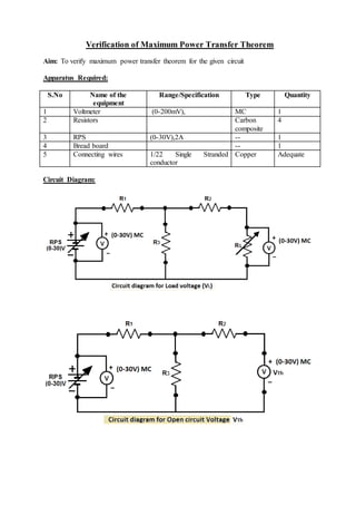
- 1. Verification of Maximum Power Transfer Theorem Aim: To verify maximum power transfer theorem for the given circuit Apparatus Required: S.No Name of the equipment Range/Specification Type Quantity 1 Voltmeter (0-200mV), MC 1 2 Resistors Carbon composite 4 3 RPS (0-30V),2A -- 1 4 Bread board -- 1 5 Connecting wires 1/22 Single Stranded conductor Copper Adequate Circuit Diagram:
- 2. Tabular column: S.No V (Volts) R (Ohms) P=V2/R (Watts)
- 3. Procedure: 1. Connections are given as per the diagram and set a particular voltage in RPS. 2. Vary RL and note down the corresponding voltmeter reading and measure the load resistance. 3. Repeat the procedure for different values of RL & Tabulate it. 4. Calculate the power for each value of RL. To find Vth: 5. Remove the load, and determine the open circuit voltage using multimeter (VTh) To find Rth: 6. Remove the load and short circuit the voltage source (RPS). 7. Find the looking back resistance (RTh) using multimeter. Equivalent Circuit: 8. Set (VTh) using RPS and RTh and note down the voltmeter reading. 9. Calculate the power delivered to the load (RL = RTh) 10. Verify maximum transfer theorem. Theoretical calculation: VTh = I R3 I is the circuit current when RL is removed I = 𝑉 𝑅1+𝑅2 VTh is the drop across R3 when RL is removed RTh = (R1 // R3) + R2 (OR) RTh = VTh / ISC ISC = 𝑉𝑇ℎ 𝑅𝑇ℎ IL = 𝑉𝑇ℎ 𝑅𝑇ℎ+𝑅𝐿 Power P= I2 RL OR P = 𝑉2 𝑅𝐿
- 4. Model graph: Precautions: 1. Voltage control knob of RPS should be kept at minimum position. 2. Current control knob of RPS should be kept at maximum position. Result: