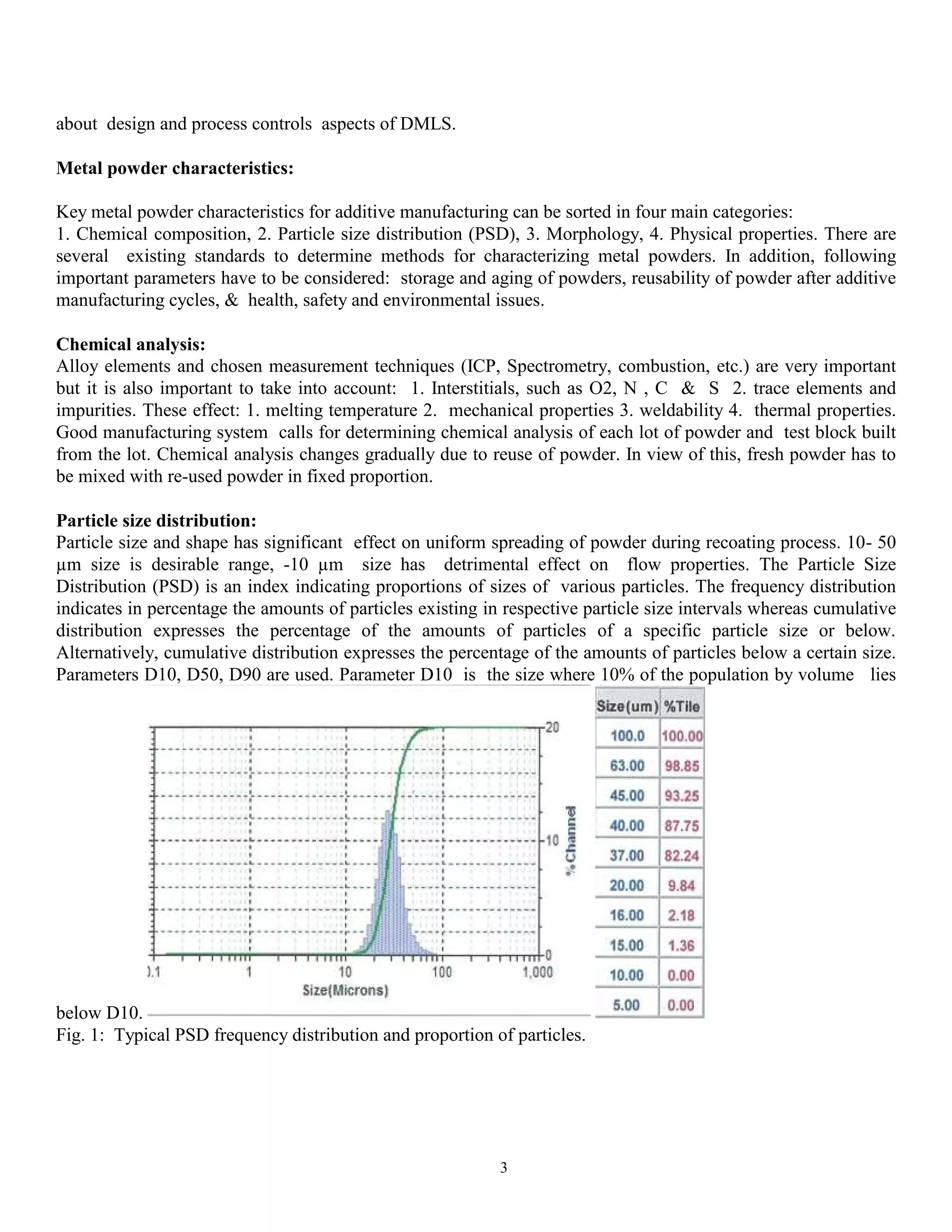
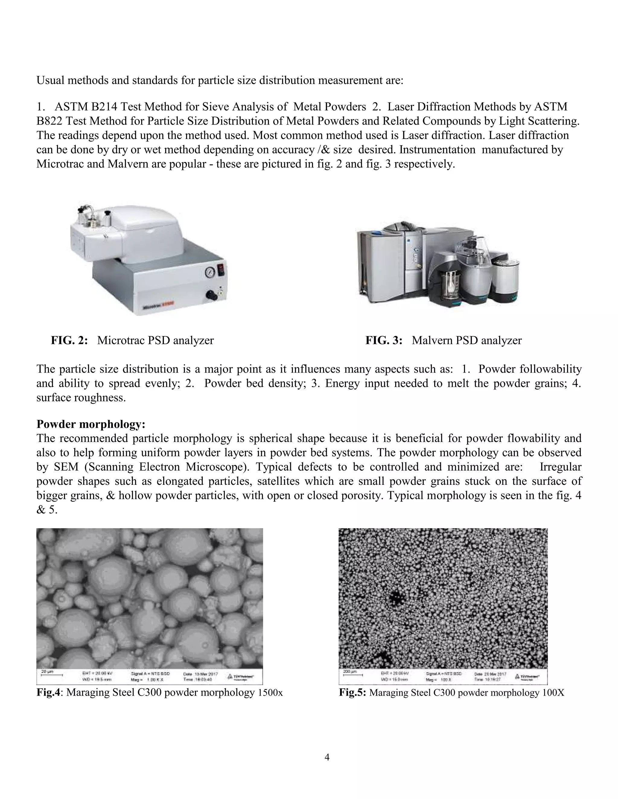
This document provides an overview of Direct Metal Laser Sintering (DMLS), an additive manufacturing technology used to create metal parts layer by layer. It discusses various aspects of process control and research and development, including powder quality, mechanical properties, and post-processing techniques. Key parameters for optimizing the DMLS process are also highlighted, emphasizing their impact on the quality, performance, and capabilities of the manufactured components.

![1
ADMAT 2017 (SkyMat)
December 14-16, 2017, Thiruvananthapuram, INDIA
Process Control & R+D in Metal Additive Manufacturing - An Overview
Jagadish Chandra Achinadkaa,1,
,
Sr. G.M (Tech. Development), 1
Intech DMLS Pvt. Ltd.
3rd Main Rd, Peenya Industrial Area Phase IV,
Peenya, Bengaluru 560058, India
a jagadish.chandra@qmaxim.com
ABSTRACT
DMLS (Direct Metal Laser Sintering), an additive manufacturing technology, is increasingly finding widespread
usage to build intricate high quality functional parts & rapid prototypes. DMLS technology uses a high intensity
laser to build components layer by layer, directly from metal powder. CAD data is directly converted to part
without the need for tooling. It is possible to build internal features and passages that are not possible in
conventional manufacturing routes.
Due to newness of technology, process control and R & D concepts are still being developed. This paper covers
various process control aspects starting with powder quality, additive manufacture, post processing, testing and
long term monitoring of quality. Following process control aspects are covered : powder chemistry, powder
particle size distribution, powder morphology, powder flow properties, DMLS process control aspects, metal
physical & mechanical properties, and NDT. Applicable international standards are also listed. Paper also
briefly touches research and developmental approach for development of new materials.
Key words
Direct Metal Laser Sintering (DMLS), Process control, CMM, powder properties, metal physical and
mechanical properties, metallurgical properties, development approach.
INTRODUCTION
Additive manufacturing (AM), which is also called 3D printing is a process of making a 3D solid object
of virtually any shape directly from a digital model. Paper [2] gives a overview of various AM processes. The
material is deposited layer by layer, unlike subtractive manufacturing which relies on the removal of material
by methods such as cutting or milling. DMLS (also called SLM process) is one of the leading Powder Bed
Fusion technologies that uses laser for fabricating metal parts directly [3]. Build station is lowered after each
melt layer and new powder layer is dispensed. This process is continued until entire part is built. The main](https://image.slidesharecdn.com/processcontrolrdinmetaladditivemanufacturing-191225081831/75/Process-control-and-R-D-in-metal-additive-manufacturing-2-2048.jpg)
![2
advantages of this technology include freedom of design, elimination of tooling, greatly reduced part
development cycle, light-weighting, part consolidation and elimination of production steps[3]. Various metals
can be manufactured by this process, most common ones being - AlSi10Mg, Ti64, IN718, IN 625, Hastealloy-X,
Co-Cr-Mo F75, 18% Maraging Steel C300,SS316L, 17-4PH [3]. DMLS now finds widespread usage in various
industrial sectors such as aerospace, energy, automotive, medical, oil and gas, tooling and consumer goods.
Process description:
In the DLMS process, a powder layer is first applied on a building platform with a recoater (blade or roller) and
a laser beam selectively melts the layer of powder. Then the platform is lowered by 20 μm to 100 μm and a new
powder layer is applied. The laser beam melting operation is repeated. After a few thousand cycles (depending
on height of the part), the built part is removed from the powder bed. Parts are built using with Nd-YAG laser
under N2/Ar atmosphere. The parts are built on a platform 20-45 mm thick made of Steel or other materials
such as Ti64. Most common build envelop is in 250 x 250 x 300mm range, now machines are available with
one dimension >=500 mm size. Laser power typically varies from 200 W up to 1000 W & with one or more
Lasers in different machines. During laser melting the weld pool is heated very rapidly and some of the
powder is converted into a gaseous condensate of the alloy - a mist of nano-particles. Rapid heating can also
lead to some larger droplets of liquid metal being ejected from the weld pool, whilst trapped gas inside powder
grains may also generate 'splatter'. DMLS machines provide inert gas flow across the bed to carry these by-
products away to prevent them from accumulating in the powder. For collecting this byproduct these machines
come with a recirculating filter system. This consists of particle separator, pre-filter and fine filter. The
byproduct, which is called condensate is collected in the recirculating filter system.
Most of the machine DMLS build parameters which number over 200 are user settable. Commonly changed
build parameters are: power, hatch distance, scan speed, scan strategy, layer thickness, offset distance, etc. The
stripe pattern can also be changed. Making these changes influence porosity level, microstructure, surface
roughness, residual stress and heat build-up in the finished the metal components.
The manufacturing of a metal part starts with 3D modeling. Then data preparation is organized & includes the
definition of part orientation, the positioning of support structures and the slicing of the model. After part
manufacturing by DMLS, post processing operations are done. These includes removal of powder, support
structures and platform. This may be followed by CMM, NDT, heat treatment, Hot isostatic pressing (HIP),
surface finish, polishing, etc.
PROCESS CONTROL
Metal Powder manufacture
Metal powder plays a very important role in the additive manufacturing processes. Powder quality has major
influence on mechanical properties but it can also influence - build-to-build consistency, reproducibility,
production of defect-free components, surface quality. Metal powders are usually produced using the gas
atomization process, where a molten metal stream is atomized due to a high pressure neutral gas jet into small
metal droplets thus forming metal powder particles after rapid solidification. Gas atomization results in
spherical shape of the powder, which is very beneficial for powder flowability. Gas atomization is the preferred
method because it leads to - a good powder density, due to the spherical shape and particle size distribution, a
good reproducibility of particle size distribution. In the VIM gas atomization process, the melting takes place in
a vacuum chamber. This process is recommended for superalloys so as to avoid gas pickup particularly
oxygen which is not desirable for Superalloys or reactive metals such as Ti. Source [1] provides a overview](https://image.slidesharecdn.com/processcontrolrdinmetaladditivemanufacturing-191225081831/75/Process-control-and-R-D-in-metal-additive-manufacturing-3-2048.jpg)

![6
Test artifact to highlight the capabilities of machine & process :
Establishing criteria for identifying and quantifying system errors is complicated mainly because of the
difficulty in separating machine characteristics from process characteristics. For evaluating the machine &
process performance a test artifact has been developed by National Institute of Standards and Technology
(NIST), USA. Paper [4] has detailed information about the artifact. This is shown in fig. 7 .
Fig.7: Test artifact showing a top view (left) and an oblique view (right) (credit: NIST)
The artifact was designed to determine the following : 1. Errors in positioning of the laser beam (resulting from
geometric errors of the two axes of rotation holding the laser beam positioning mirrors or form errors in the f-θ
lens that focuses and shapes the laser beam spot), 2. geometric errors of the axis positioning the build platform,
3. alignment errors between the axes, 4. errors in the laser beam size and shape, 5. variation in the beam power.
The part should be built in the center of the building platform with the 4 mm pins and holes aligned along the
machine x- and y-axes. Part as built is 17 mm tall and has a volume of approximately 101000 mm3
. The
diamond shape was chosen because it minimizes the impact between the recoating blade and each layer of the
part, and it allows simple vertical mounting for various measurements. Periodically this test is done to monitor
state of machine and the process. Machine is adjusted/ recalibrated based on the findings.
Measurements of metal properties:
For good process control it is necessary to periodically measure some of the following metal properties :
dimension, density, hardness, roughness, hardness, tensile properties, microstructure. Depending on application,
mechanical properties such as high temperature tensile, stress rupture, creep test, creep rupture, fatigue are also
measured. Mechanical properties are measured in as built and heat treated condition. Common heat treatments
given are : stress relief, aging, solutionizing + aging treatment. Test cubes or specimens are built along with
build platform. Mechanical properties of the parts built by this process display some amount of anisotropy,
hence properties have to be tested in various orientations, at the least in horizontal and vertical directions.
Physical properties:
Coordinate measuring system (CMM) is used for measuring dimensional accuracy. Measurements are done by
probe. Probes could be mechanical, optical, laser or white light. Measurement could be manual or computer
controlled or combination of the two.](https://image.slidesharecdn.com/processcontrolrdinmetaladditivemanufacturing-191225081831/75/Process-control-and-R-D-in-metal-additive-manufacturing-7-2048.jpg)

![8
Fig.8: Slice of tracking plot showing roughness histogram of various alloys
RESEARCH AND DEVELOPMENT
Several materials are certified for production of quality parts by DMLS process – more are being added.
However, quite often it is necessary to tweak operating conditions to improve one or more of the following–
productivity, yield, cost reduction, room temperature mechanical properties, elevated temperature mechanical
properties, surface roughness, microstructure, etc. To achieve this one or more of the following is fine-tuned viz.
machine operating parameters, process conditions, heat treatment, post processing, etc. If the standard operating
conditions do not exist they have to developed from scratch. There are several approaches for doing this. Papers
[5], [6] describe two such approaches. Another approach is use of statistical technique of design of experiment
(DoE) - which is explained in this paper.
Following is a broad approach for process development and parameter optimization. For each material a
specific range of parameters combination exists that result in satisfactory quality such as - high density,
microstructure or surface roughness. Productivity also should be considered. The optimum parameter window is
experimentally determined - most common method being DoE. Taguchi method (TM) and Response surface
methodology (RSM) are most common DoE methodologies. In statistical-based approaches, RSM has been
extensively used for optimization. RSM is a collection of statistical techniques for designing experiments,
building models, evaluating the effects of factors and searching for the optimum conditions. It is a statistically
designed experimental protocol in which several factors are simultaneously varied. In RSM, the experimental
responses of experiments (DoEs) are fitted to quadratic function. Artificial neural network (ANN) has emerged
as an attractive tool for non-linear multivariate modeling. The power of ANN is that it is generic in structure and
possesses the ability to learn from historical data. The main advantage of ANN compared to RSM are: (i) ANN
does not require a prior specification of suitable fitting function and (ii) ANN has universal approximation
capability, i.e. it can approximate almost all kinds of non-linear functions including quadratic functions,
whereas RSM is useful only for quadratic approximations.
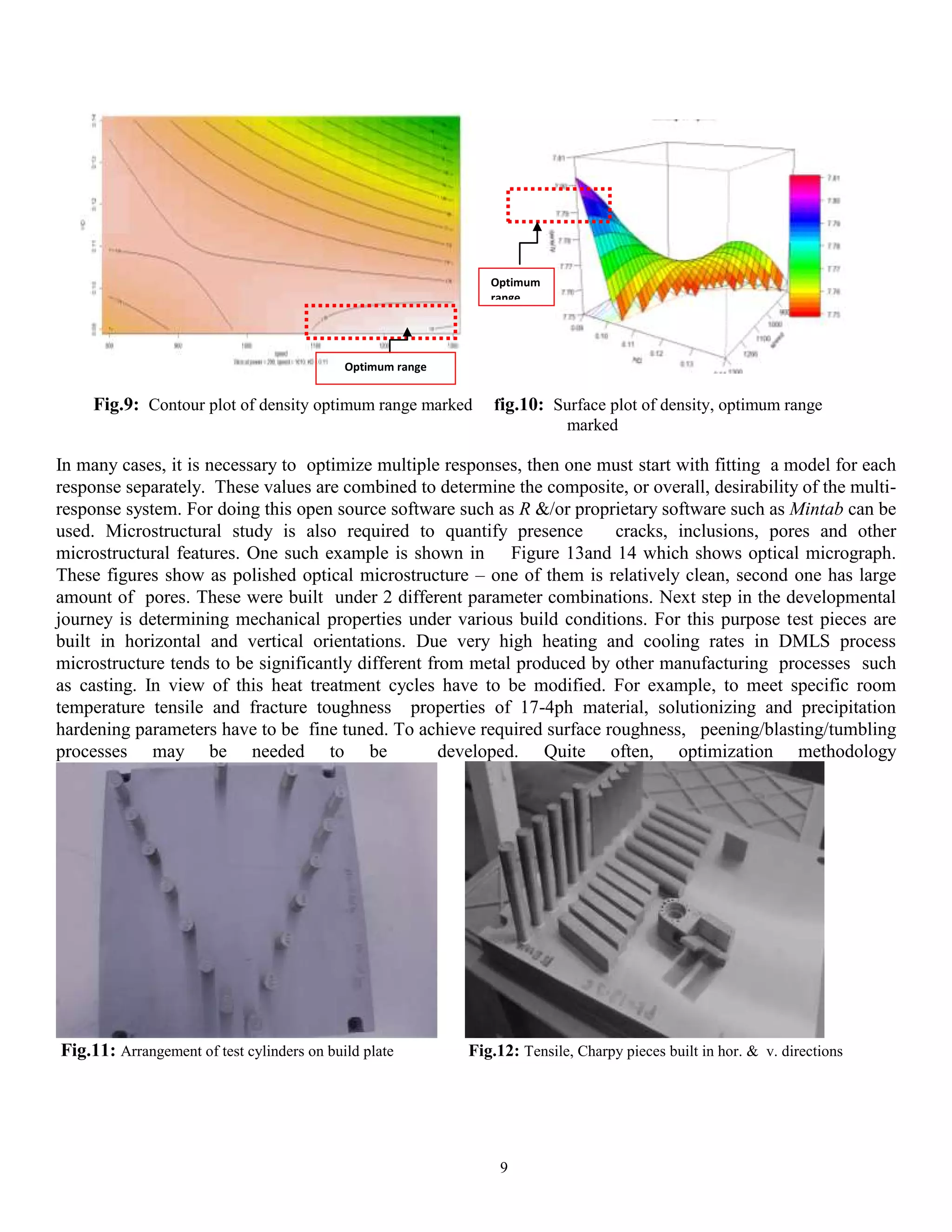
Series of test blocks are built under statistically determined conditions and responses are measured. Examples
are shown in figures 11 and 12. Several builds may be required to arrive at optimum operating window. In
many cases, interactions may exist between factors thus necessitating plotting of contour and surface plots.
Figures 9 and 10 show such an example. From this optimum operating range is extracted.](https://image.slidesharecdn.com/processcontrolrdinmetaladditivemanufacturing-191225081831/75/Process-control-and-R-D-in-metal-additive-manufacturing-9-2048.jpg)
![10
Fig.13: microstructure as polished 100X, clean Fig.14: microstructure, as polished 100X, more pores
such as DoE has to be used for discovering optimum process conditions.
CONCLUSION
This paper covers various process control aspects of DMLS process starting with powder all the way up to final part
production. A brief overview of research and development aspects of parameter and process optimization are also
covered.
REFERENCES
[1] “Getting the Most Out of Metal 3D Printing: Understanding Design and Process Controls for DMLS”
[2] W. J. Sames, F. A. List, S. Pannala, R. R. Dehoff & S. S. Babu (2016), “The metallurgy and processing
science of metal additive manufacturing”, Second edition , International Materials Reviews Volume 61, 2016 -
Issue 5
[3] Bhavar, V., Kattire, P. and Pawar, P. (2014) “A Review on Powder Bed Fusion Technology
of Additive Manufacturing”, 4th International conference & exhibition on Additive manufacturing
Technologies-AM-2014.
[4] S.P. Moylan, J.A. Slotwinski, A.L. Cooke, K.K. Jurrens, and M.A. Donmez (2012), "Proposal for a
standardized test artifact for additive manufacturing machines and processes," Proceedings of the 23rd
International Solid Free Form Symposium – An Additive Manufacturing Conference, Austin, TX, USA, August
2012, pp. 902-920.
[5] Xuezhi Shi, Shuyuan Ma, Changmeng Liu ,Qianru Wu (2017), “Parameter optimization for Ti-47Al-2Cr-
2Nb in selective laser melting based on geometric characteristics of single scan tracks”, Optics & Laser
Technology Volume 90, 1 May 2017, Pages 71-79
[6] Zhiheng Hu, Haihong Zhun, Hu Zhang, Xiaoyan Zeng (2017), Experimental investigation on selective laser
melting of 17-4PH stainless steel A, Optics & Laser Technology 87 (2017) 17–25
View publication statsView publication stats](https://image.slidesharecdn.com/processcontrolrdinmetaladditivemanufacturing-191225081831/75/Process-control-and-R-D-in-metal-additive-manufacturing-11-2048.jpg)


