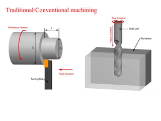
Turning, boring, drilling,milling, shaping, planing, broaching, slotting,
grinding etc.
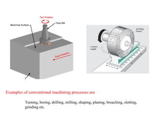
Examples of conventional machining processes are
11.
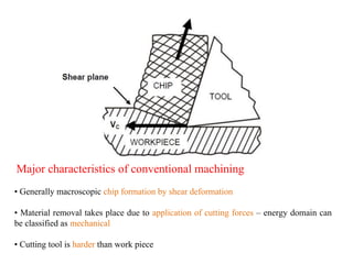
Major characteristics ofconventional machining
• Generally macroscopic chip formation by shear deformation
• Material removal takes place due to application of cutting forces – energy domain can
be classified as mechanical
• Cutting tool is harder than work piece
12.
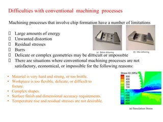
Difficulties with conventionalmachining processes
Machining processes that involve chip formation have a number of limitations
Large amounts of energy
Unwanted distortion
Residual stresses
Burrs
Delicate or complex geometries may be difficult or impossible
There are situations where conventional machining processes are not
satisfactory, economical, or impossible for the following reasons:
• Material is very hard and strong, or too brittle.
• Workpiece is too flexible, delicate, or difficult to
fixture.
• Complex shapes.
• Surface finish and dimensional accuracy requirements.
• Temperature rise and residual stresses are not desirable.
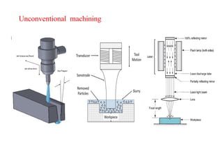
Non-traditional machining (NTM)processes have several advantages
• Complex geometries are possible
• Extreme surface finish
• Tight tolerances
• Delicate components
• Little or no burring or residual stresses
• Brittle materials with high hardness can be machined
• Microelectronic or integrated circuits are possible to mass produce
15.
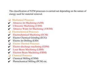
The classification ofNTM processes is carried out depending on the nature of
energy used for material removal.
❑ Mechanical Processes
✔ Abrasive Jet Machining (AJM)
✔ Ultrasonic Machining (USM)
✔ Abrasive Water Jet Machining (AWJM)
❑ Electrochemical Processes
✔ Electrochemical Machining (ECM)
✔ Electro Chemical Grinding (ECG)
✔ Electro Jet Drilling (EJD)
❑ Electro-Thermal Processes
✔ Electro-discharge machining (EDM)
✔ Laser Beam Machining (LBM)
✔ Electron Beam Machining (EBM)
❑ Chemical Processes
✔ Chemical Milling (CHM)
✔ Photochemical Milling (PCM) etc.
16.
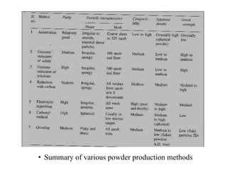
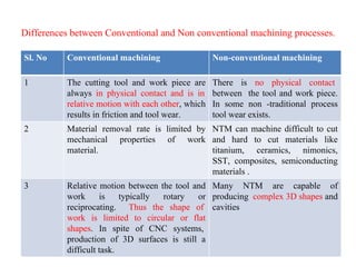
Sl. No Conventionalmachining Non-conventional machining
1 The cutting tool and work piece are
always in physical contact and is in
relative motion with each other, which
results in friction and tool wear.
There is no physical contact
between the tool and work piece.
In some non -traditional process
tool wear exists.
2 Material removal rate is limited by
mechanical properties of work
material.
NTM can machine difficult to cut
and hard to cut materials like
titanium, ceramics, nimonics,
SST, composites, semiconducting
materials .
3 Relative motion between the tool and
work is typically rotary or
reciprocating. Thus the shape of
work is limited to circular or flat
shapes. In spite of CNC systems,
production of 3D surfaces is still a
difficult task.
Many NTM are capable of
producing complex 3D shapes and
cavities
Differences between Conventional and Non conventional machining processes.
17.
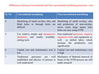
Sl. No Conventionalmachining Non-conventional machining
4 Machining of small cavities, slits, and
blind holes or through holes are
difficult
Machining of small cavities, slits
and production of non-circular,
micro sized, large aspect ratio
holes are easy using NTM
5 Use relative simple and inexpensive
machinery and readily available
cutting tools
Non traditional processes requires
expensive tools and equipment as
well as skilled labor, which
increase the production cost
significantly
6 Capital cost and maintenance cost is
low.
Capital cost and maintenance cost
is high
7 Traditional processes are well
established and physics of process is
well understood
Mechanics of Material removal of
Some of the NTM process are still
under research
Differences between Conventional and Non conventional machining processes- cont.
18.
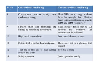
Sl. No Conventionalmachining Non-conventional machining
8 Conventional process mostly uses
mechanical energy
Most NTM uses energy in direct
form. For example : laser, Electron
beam in its direct forms are used in
LBM and EBM respectively
9 Surface finish and tolerances are
limited by machining inaccuracies
High surface finish (up to 0.1
micron) and tolerances (25
microns) can be achieved
10 High metal removal rate. Low material removal rate.
11 Cutting tool is harder than workpiece. There may not be a physical tool
present
12 Tool life is less due to high surface
contact and wear
Tool life is more
13 Noisy operation Quiet operation mostly
Why Micro Machining?
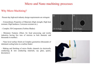
Presentday high-tech industry design requirements are stringent.
– Extraordinary Properties of Materials (High strength, High heat
resistant, High hardness, Corrosion resistant etc.)
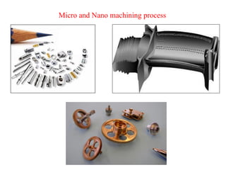
– Complex 3D Components (Turbine Blades)
– Miniature Features (filters for food processing and textile
industries having few tens of microns as hole diameter and
thousands in number)
– Nano level surface finish on Complex geometries (thousands of
tubulated cooling holes in a turbine blade)
– Making and finishing of micro fluidic channels (in electrically
conducting & non conducting materials, say glass, quartz,
&ceramics)
21.
Why Micro Machining?
❖Final finishing operations in manufacturing of precise parts are always
of concern owing to their most critical, labor intensive and least
controllable nature.
❖ In the era of nanotechnology, deterministic high precision finishing
methods are of utmost importance and are the need of present
manufacturing scenario.
❖ The need for high precision in manufacturing was felt by
manufacturers worldwide to improve interchangeability of
components, improve quality control and longer wear/fatigue life.
22.
Micro and Nanomachining processes
❖ High cost processes equipments
❖ Sensitive to environmental conditions
❖ Strict standardization is required.
❖ Tool holder and tool manufacturing is highly expensive.
❖ Less available research and date.
Challenges:
23.
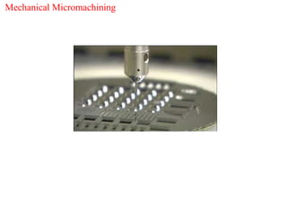
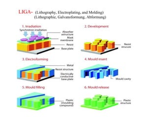
Different Micro/nano machiningtechniques
• Mechanical Micromachining
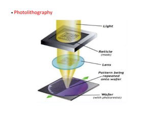
• Photolithography
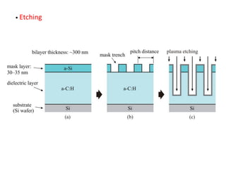
• Etching
• Silicon Micromachining
• LIGA
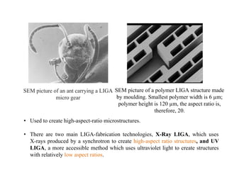
SEM picture ofan ant carrying a LIGA
micro gear
SEM picture of a polymer LIGA structure made
by moulding. Smallest polymer width is 6 µm;
polymer height is 120 µm, the aspect ratio is,
therefore, 20.
• Used to create high-aspect-ratio microstructures.
• There are two main LIGA-fabrication technologies, X-Ray LIGA, which uses
X-rays produced by a synchrotron to create high-aspect ratio structures, and UV
LIGA, a more accessible method which uses ultraviolet light to create structures
with relatively low aspect ratios.
29.
The notable characteristicsof X-ray LIGA-fabricated
structures include:
•high aspect ratios on the order of 100:1
•parallel side walls with a flank angle on the order of
89.95°
•smooth side walls with Ra = 10 nm, suitable for optical
mirrors
•structural heights from tens of micrometers to several
millimeters
•structural details in the order of micrometers over
distances of centimeters
30.
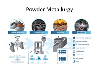
Part 2: POWDERMETALLURGY
Need of P/M- Powder production methods: Atomization,
electrolysis, reduction of oxides, carbonyls (Process parameters,
characteristics of powder produced in each method)
Introduction
⚫ Powder metallurgymay be defined as the art of producing
metal powders and using them to make serviceable objects.
⚫ Powder metallurgy principles were used far back in 3000 B.C.
by the Egyptians to make iron parts.
⚫ The use of gold, silver, copper & brass powders for ornaments
was common during the middle age.
⚫ Recently, materials with mechanical properties far better than
those of conventional materials have been developed by
improving heat-treatment, powder composition and processing
methods to achieve higher densities.
33.
Importance of P/M
•Attainment of precise compositions and properties not possible
by the conventional methods of melting and casting.
• Economically viable mass production method for structural
components to very close tolerance.
• The process involves producing metallic parts from metallic
powders of a single metal, of several metals or of a combination
of metals and non-metals by applying pressure.
• The powders are mixed mechanically, compacted into a
particular shape and then heated at elevated temperature below
the melting point of the main constituent.
Basic process ofpowder metallurgy
The four basic operation of the powder metallurgy
technique are:
1. Manufacture of powder
2. Mixing or blending powder particles
3. Compacting and,
4. Sintering
36.
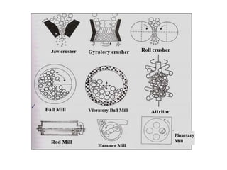
Production of metalpowder
1.Mechanical methods
Cheapest of the powder production methods; These
methods involve using mechanical forces such as
compressive forces, shear or impact to facilitate particle
size reduction of bulk materials; Eg.:Milling
38.
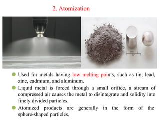
2. Atomization
⚫ Usedfor metals having low melting points, such as tin, lead,
zinc, cadmium, and aluminum.
⚫ Liquid metal is forced through a small orifice, a stream of
compressed air causes the metal to disintegrate and solidity into
finely divided particles.
⚫ Atomized products are generally in the form of the
sphere-shaped particles.
39.
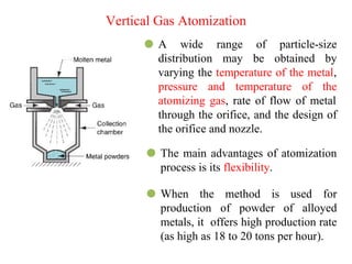
⚫ A widerange of particle-size
distribution may be obtained by
varying the temperature of the metal,
pressure and temperature of the
atomizing gas, rate of flow of metal
through the orifice, and the design of
the orifice and nozzle.
⚫ The main advantages of atomization
process is its flexibility.
⚫ When the method is used for
production of powder of alloyed
metals, it offers high production rate
(as high as 18 to 20 tons per hour).
Vertical Gas Atomization
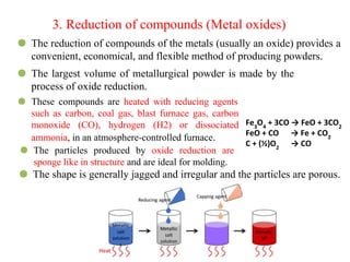
3. Reduction ofcompounds (Metal oxides)
⚫ The reduction of compounds of the metals (usually an oxide) provides a
convenient, economical, and flexible method of producing powders.
⚫ The largest volume of metallurgical powder is made by the
process of oxide reduction.
⚫ These compounds are heated with reducing agents
such as carbon, coal gas, blast furnace gas, carbon
monoxide (CO), hydrogen (H2) or dissociated
ammonia, in an atmosphere-controlled furnace.
⚫ The particles produced by oxide reduction are
sponge like in structure and are ideal for molding.
⚫ The shape is generally jagged and irregular and the particles are porous.
Fe3
O4
+ 3CO → FeO + 3CO2
FeO + CO → Fe + CO2
C + (½)O2
→ CO
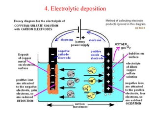
⚫ The methodof electrolytic deposition is most suitable for the
production of extremely pure powder of principally copper
and iron.
⚫ Electrolysis is similar to electroplating.
⚫ By regulation of current density, temperature, circulation of
electrolyte, and proper choice of electrolyte, the powder may
be directly deposited from the electrolyte.
⚫ The deposit at the bottom of cathode in the tank is periodically
removed during the process.
⚫ The deposit may be a soft spongy substance which is
subsequently ground to powder, or the deposit may be a hard,
brittle metal.
46.
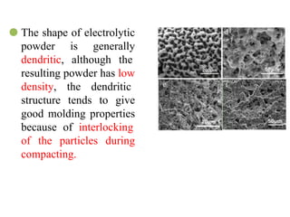
⚫ The shapeof electrolytic
powder is generally
dendritic, although the
resulting powder has low
density, the dendritic
structure tends to give
good molding properties
because of interlocking
of the particles during
compacting.
47.
5. The CarbonylProcess
• This method is based on the fact that metals can react with CO to
form carbonyls
• When iron and nickel ores react under high pressure (70 – 300
atm.) with carbon monoxide, iron pentacarbonyl [Fe(CO)5] or
nickel tetracarbonyl [Ni(CO)4] is formed, respectively.
• Both compounds are liquids at room temperature.
• The liquid carbonyles are stored under pressure in tanks
submerged in water.
• The distilled and filtered liquids are conveyed to steam heating
cylinders, where they are vaporized.
48.
• The vaporsof liquid are sent to decomposers which are
cylinders having 9 – 10 feet high with an internal dia. of 3 feet,
with conical bottoms.
• The incoming stream of vapors meets a tangential stream of
ammonia gas. CO is removed here and precipitates of metals are
formed which are then sieved, dried and may be milled to break
up the agglomerates.
• The CO gas arising from the decomposition is recovered and
re-used.
• Carbonyl iron powder is used for the production of magnetic
powder cores for radio or television applications.
Powder Characterization
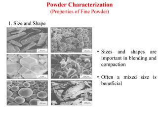
(Properties ofFine Powder)
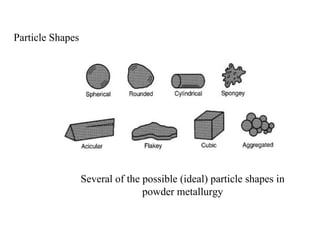
1. Size and Shape
• Sizes and shapes are
important in blending and
compaction
• Often a mixed size is
beneficial
51.
51
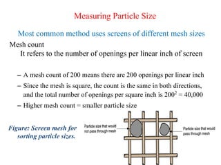
Measuring Particle Size
Mostcommon method uses screens of different mesh sizes
Mesh count
It refers to the number of openings per linear inch of screen
– A mesh count of 200 means there are 200 openings per linear inch
– Since the mesh is square, the count is the same in both directions,
and the total number of openings per square inch is 2002
= 40,000
– Higher mesh count = smaller particle size
Figure: Screen mesh for
sorting particle sizes.
53
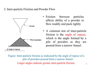
2. Inter-particle Frictionand Powder Flow
• Friction between particles
affects ability of a powder to
flow readily and pack tightly
Figure: Inter-particle friction as indicated by the angle of repose of a
pile of powders poured from a narrow funnel.
Larger angles indicate greater inter-particle friction.
• A common test of inter-particle
friction is the angle of repose,
which is the angle formed by a
pile of powders as they are
poured from a narrow funnel.
54.
54
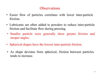
Observations
• Easier flowof particles correlates with lower inter-particle
friction.
• Lubricants are often added to powders to reduce inter-particle
friction and facilitate flow during pressing.
• Smaller particle sizes generally show greater friction and
steeper angles.
• Spherical shapes have the lowest inter-particle friction.
• As shape deviates from spherical, friction between particles
tends to increase.
55.
55
3. Particle Density
Truedensity
density of the true volume of the material
– The density of the material, if the powders were
melted into a solid mass
Because of pores between particles, bulk density is
less than true density.
Bulk density
- density of the powders in the loose state after
pouring
56.
56
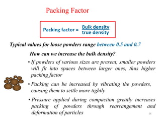
Packing Factor
Typical valuesfor loose powders range between 0.5 and 0.7
Bulk density
true density
Packing factor =
• If powders of various sizes are present, smaller powders
will fit into spaces between larger ones, thus higher
packing factor
How can we increase the bulk density?
• Packing can be increased by vibrating the powders,
causing them to settle more tightly
• Pressure applied during compaction greatly increases
packing of powders through rearrangement and
deformation of particles
57.
57
4. Porosity
Ratio ofvolume of the pores (empty spaces) in the powder to the
bulk volume
•In principle
Porosity + Packing factor = 1.0
• During compaction of powder these spaces are eliminated
• If any amount of space remains after processing, it will result in
porosity in the manufactured part.
58.
5. Surface area
•Powders have an extremely high surface area and it increases with
reduction in particle size.
• High surface area enhances the interactions during compacting
6. Compressibility
• Indicates the ability of a powder to undergo compression.
• Presence of lubricants can improve compressibility
7. Purity
• Powders should be free from impurities.
59.
59
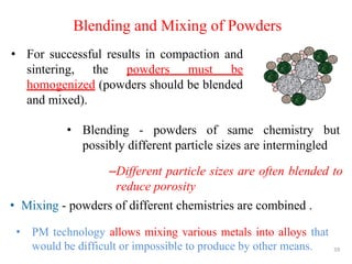
Blending and Mixingof Powders
• Mixing - powders of different chemistries are combined .
• For successful results in compaction and
sintering, the powders must be
homogenized (powders should be blended
and mixed).
• Blending - powders of same chemistry but
possibly different particle sizes are intermingled
–Different particle sizes are often blended to
reduce porosity
• PM technology allows mixing various metals into alloys that
would be difficult or impossible to produce by other means.
60.
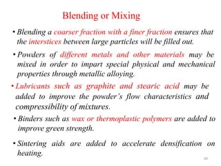
Blending or Mixing
•Blending a coarser fraction with a finer fraction ensures that
the interstices between large particles will be filled out.
60
• Powders of different metals and other materials may be
mixed in order to impart special physical and mechanical
properties through metallic alloying.
• Lubricants such as graphite and stearic acid may be
added to improve the powder’s flow characteristics and
compressibility of mixtures.
• Binders such as wax or thermoplastic polymers are added to
improve green strength.
• Sintering aids are added to accelerate densification on
heating.
61.
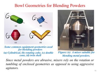
Bowl Geometries forBlending Powders
Figure: (e) A mixer suitable for
blending metal powders.
Since metal powders are abrasive, mixers rely on the rotation or
tumbling of enclosed geometries as opposed to using aggressive
agitators.
61
Some common equipment geometries used
for blending powders
(a) Cylindrical, (b) rotating cube, (c) double
cone, (d) twin shell
62.
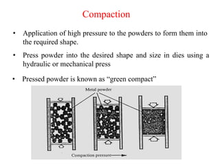
• Application ofhigh pressure to the powders to form them into
the required shape.
Compaction
• Press powder into the desired shape and size in dies using a
hydraulic or mechanical press
• Pressed powder is known as “green compact”
63.
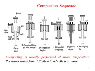
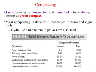
Compacting is usuallyperformed at room temperature.
Pressures range from 138 MPa to 827 MPa or more.
63
Compaction Sequence
64.
Compacting
• Loose powderis compacted and densified into a shape,
known as green compact.
64
• Most compacting is done with mechanical presses and rigid
tools.
– Hydraulic and pneumatic presses are also used.
65.
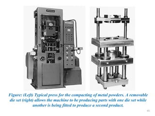
Figure: (Left) Typicalpress for the compacting of metal powders. A removable
die set (right) allows the machine to be producing parts with one die set while
another is being fitted to produce a second product.
65
66.
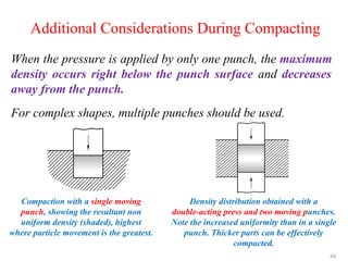
Additional Considerations DuringCompacting
When the pressure is applied by only one punch, the maximum
density occurs right below the punch surface and decreases
away from the punch.
For complex shapes, multiple punches should be used.
Compaction with a single moving
punch, showing the resultant non
uniform density (shaded), highest
where particle movement is the greatest.
Density distribution obtained with a
double-acting press and two moving punches.
Note the increased uniformity than in a single
punch. Thicker parts can be effectively
compacted.
66
67.
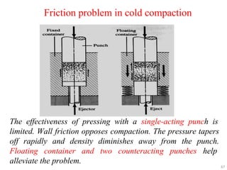
Friction problem incold compaction
The effectiveness of pressing with a single-acting punch is
limited. Wall friction opposes compaction. The pressure tapers
off rapidly and density diminishes away from the punch.
Floating container and two counteracting punches help
alleviate the problem.
67
68.
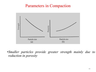
•Smaller particles providegreater strength mainly due to
reduction in porosity
68
Parameters in Compaction
69.
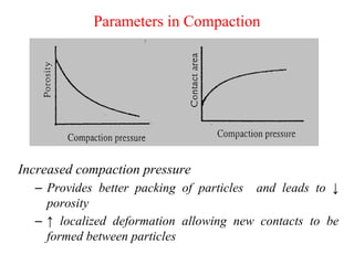
Increased compaction pressure
–Provides better packing of particles and leads to ↓
porosity
– ↑ localized deformation allowing new contacts to be
formed between particles
Parameters in Compaction
70.
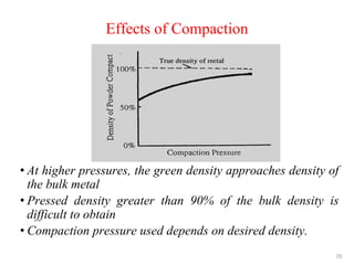
• At higherpressures, the green density approaches density of
the bulk metal
• Pressed density greater than 90% of the bulk density is
difficult to obtain
• Compaction pressure used depends on desired density.
Effects of Compaction
70
71.
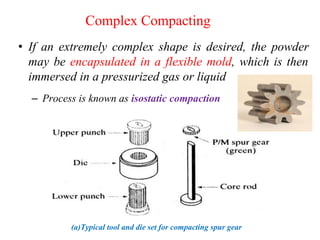
Complex Compacting
• Ifan extremely complex shape is desired, the powder
may be encapsulated in a flexible mold, which is then
immersed in a pressurized gas or liquid
– Process is known as isostatic compaction
(a)Typical tool and die set for compacting spur gear
72.
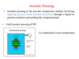
Isostatic Pressing
• Isostaticpressing is the powder compaction method involving
applying pressure from multiple directions through a liquid or
gaseous medium surrounding the compacted part.
• Cold isostatic pressing (CIP)
- Is conducted at room temperature.
73.
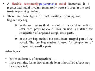
• A flexible(commonly polyurethane) mold immersed in a
pressurized liquid medium (commonly water) is used in the cold
isostatic pressing method.
• There are two types of cold isostatic pressing: wet
bag and dry bag.
❖ In the wet bag method the mold is removed and refilled
after each pressure cycle. This method is suitable for
compaction of large and complicated parts.
Advantages
• better uniformity of compaction;
• more complex forms (for example long thin-walled tubes) may
be compacted;
❖ In the dry bag method the mold is an integral part of the
vessel. The dry bag method is used for compaction of
simpler and smaller parts.
75.
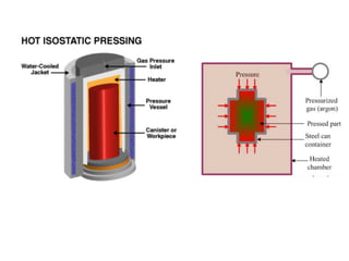
• Involves isostaticpressing conducted at increased
temperature.
Hot isostatic pressing (HIP)
• As a pressure medium a gas (Nitrogen or Argon) is used.
• The work pressures, which are applied in the hot isostatic
pressing method, are commonly between 15,000 psi to 44,000
psi (100 MPa to 300 MPa).
• Hot isostatic method (HIP) combines pressing and sintering,
causing consolidation of powder particles, healing voids and
pores. The part shrinks and densifies, forming sound high
strength structure.
76.
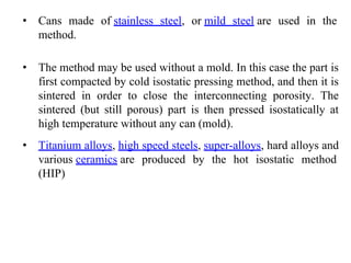
• Cans madeof stainless steel, or mild steel are used in the
method.
• The method may be used without a mold. In this case the part is
first compacted by cold isostatic pressing method, and then it is
sintered in order to close the interconnecting porosity. The
sintered (but still porous) part is then pressed isostatically at
high temperature without any can (mold).
• Titanium alloys, high speed steels, super-alloys, hard alloys and
various ceramics are produced by the hot isostatic method
(HIP)
77.
Sintering
• Sintering bondsindividual metallic particles, thereby increasing
strength and hardness of the final part.
• Compressed metal powder is heated in a controlled furnace
atmosphere to a temperature below its melting point (70% to 90%
of Tm), but high enough to cause diffusion thereby ensuring
bonding between neighboring particles.
• Powder preforms are heated in a controlled, inert or reducing
atmosphere or in vacuum to prevent oxidation.
• The primary driving force for sintering is the formation and
growth of bonds between particles due to reduced surface energy.
• Part shrinkage occurs during sintering due to pore size reduction.
• Density increases due to filling up of incipient holes and
increasing area of contact among powder particles.
78.
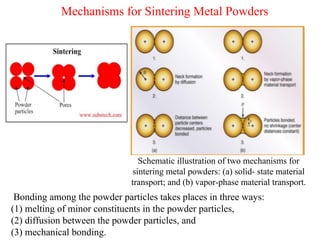
Mechanisms for SinteringMetal Powders
Bonding among the powder particles takes places in three ways:
(1) melting of minor constituents in the powder particles,
(2) diffusion between the powder particles, and
(3) mechanical bonding.
Schematic illustration of two mechanisms for
sintering metal powders: (a) solid- state material
transport; and (b) vapor-phase material transport.
79.
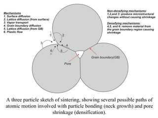
A three particlesketch of sintering, showing several possible paths of
atomic motion involved with particle bonding (neck growth) and pore
shrinkage (densification).
80.
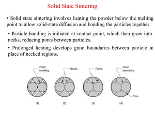
Solid State Sintering
•Solid state sintering involves heating the powder below the melting
point to allow solid-state diffusion and bonding the particles together.
• Particle bonding is initiated at contact point, which then grow into
necks, reducing pores between particles.
• Prolonged heating develops grain boundaries between particle in
place of necked regions.
81.
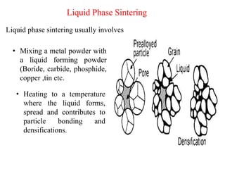
Liquid Phase Sintering
Liquidphase sintering usually involves
• Mixing a metal powder with
a liquid forming powder
(Boride, carbide, phosphide,
copper ,tin etc.
• Heating to a temperature
where the liquid forms,
spread and contributes to
particle bonding and
densifications.
82.
• The natureand strength of the bond between the particles
depends on:
1.The mechanism of diffusion,
2.Plastic flow of the powder particles, and
3.Evaporation of volatile material from the compacted preform.
• The three critical factors that control the sintering
process are:
1) time,
2) temperature and
3) the furnace atmosphere
Factors in Sintering
83.
• Joining: Bysinter bonding, staking, brazing, infiltrating, or
welding
Secondary Operations
• Sizing: To tighten dimensional tolerances, usually in the radial
direction, relative to the direction of compacting pressure
• Coining: To change axial dimensions and tolerances
• Machining: To obtain shapes that cannot be compacted, such as by
tapping holes or cutting undercut grooves
• Forming: To change the shape of the part; can be done hot or cold
• Re-pressing: To reduce porosity and increase strength and
ductility; may be accompanied by resintering
• Infiltration: To increase strength and decrease porosity
• Heat treating: To increase hardness or strength
• Finishing: Includes deburring, polishing, impregnating,
84.
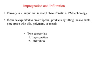
• Porosity isa unique and inherent characteristic of PM technology.
Impregnation and Infiltration
• It can be exploited to create special products by filling the available
pore space with oils, polymers, or metals
• Two categories:
1. Impregnation
2. Infiltration
85.
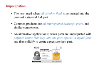
• The termused when oil or other fluid is permeated into the
pores of a sintered PM part
Impregnation
• Common products are oil-impregnated bearings, gears, and
similar components.
• An alternative application is when parts are impregnated with
polymer resins that seep into the pore spaces in liquid form
and then solidify to create a pressure tight part.
86.
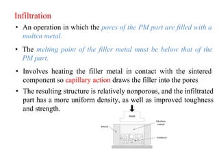
• An operationin which the pores of the PM part are filled with a
molten metal.
Infiltration
• The melting point of the filler metal must be below that of the
PM part.
• Involves heating the filler metal in contact with the sintered
component so capillary action draws the filler into the pores
• The resulting structure is relatively nonporous, and the infiltrated
part has a more uniform density, as well as improved toughness
and strength.
87.
Advantages
• Parts canbe produced from high melting point refractory metals
with respectively less difficulty and at less cost.
• Production rates are high even for complex parts. This is
primarily because of the use of automated equipment in the
process
• Near net shape components are produced. The dimensional
tolerances on components are mostly such that no further
machining is needed. Scrap is almost negligible.
• Parts can be made from a great variety of compositions. It is
therefore much easy to have parts of desired mechanical and
physical properties like density, hardness toughness, stiffness,
damping, and specific electrical or magnetic properties.
• Extremely good surface finish
88.
• Parts canbe produced with impregnation and infiltration of
other materials to obtain special characteristics needed for
specific applications
• Skilled machinists are not needed, so labour cost is low
• Parts with controlled porosity can be produced
• Bi-metallic products, sintered carbides and porous bearings can
be produced only by this process
• The production can be fully automated, therefore,
Mass production is possible
Production rate is high
Over-head costs are low
Break even point is not too large
Material loss is small
89.
Limitations
• High costof metal powders compared to the cost of raw
material used for casting or forging a component. A few
powders are even difficult to store without some deterioration.
• High cost of tooling and equipment. This is particularly a
limitation when production volumes are small.
• Large or complex shaped parts are difficult to produce by PM
process
• Parts have lower ductility and strength than those produced by
forging
• Uniformly high density products are difficult to produce.
• Problems in storing and handling metal powders.
90.
• Some powders(such as aluminum, magnesium, titanium and
zirconium) in a finally divided state present fire hazard and risk of
explosion.
• Low melting point metal powders (such as of zinc, tin, cadmium)
give thermal difficulties during sintering operation, as most oxides
of these metals cannot be reduced at temperatures below the
melting point.
• Degradation over time
• Limitations on part geometry due to limited flowability of
powders.
• Copper-based materials which are hot-worked have not so far
been made by PM successfully.
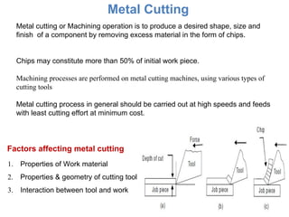
Metal Cutting
99
Metal cuttingor Machining operation is to produce a desired shape, size and
finish of a component by removing excess material in the form of chips.
Chips may constitute more than 50% of initial work piece.
Machining processes are performed on metal cutting machines, using various types of
cutting tools
Metal cutting process in general should be carried out at high speeds and feeds
with least cutting effort at minimum cost.
Factors affecting metal cutting
1. Properties of Work material
2. Properties & geometry of cutting tool
3. Interaction between tool and work
101
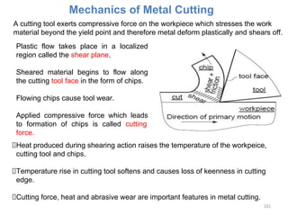
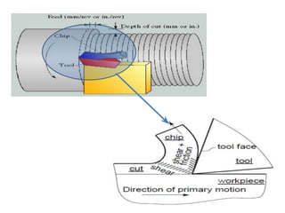
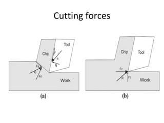
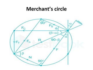
Mechanics of MetalCutting
A cutting tool exerts compressive force on the workpiece which stresses the work
material beyond the yield point and therefore metal deform plastically and shears off.
Plastic flow takes place in a localized
region called the shear plane.
Sheared material begins to flow along
the cutting tool face in the form of chips.
Flowing chips cause tool wear.
Applied compressive force which leads
to formation of chips is called cutting
force.
Heat produced during shearing action raises the temperature of the workpeice,
cutting tool and chips.
Temperature rise in cutting tool softens and causes loss of keenness in cutting
edge.
Cutting force, heat and abrasive wear are important features in metal cutting.
103
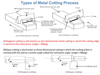
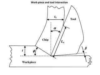
Types of MetalCutting Process
Orthogonal cutting is also known as two dimensional metal cutting in which the cutting edge
is normal to the work piece. (angle = 90deg)
Oblique cutting is also known as three dimensional cutting in which the cutting action is
inclined with the job by a certain angle called the inclination angle. (angle ≠ 90deg)
104.
104
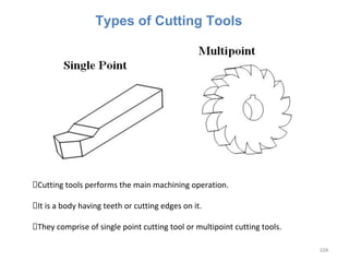
Cutting tools performsthe main machining operation.
It is a body having teeth or cutting edges on it.
They comprise of single point cutting tool or multipoint cutting tools.
Types of Cutting Tools
105.
105
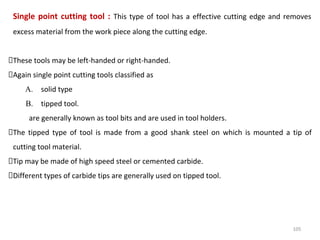
Single point cuttingtool : This type of tool has a effective cutting edge and removes
excess material from the work piece along the cutting edge.
These tools may be left-handed or right-handed.
Again single point cutting tools classified as
A. solid type
B. tipped tool.
are generally known as tool bits and are used in tool holders.
The tipped type of tool is made from a good shank steel on which is mounted a tip of
cutting tool material.
Tip may be made of high speed steel or cemented carbide.
Different types of carbide tips are generally used on tipped tool.
106.
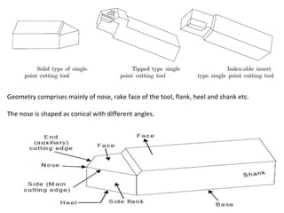
106
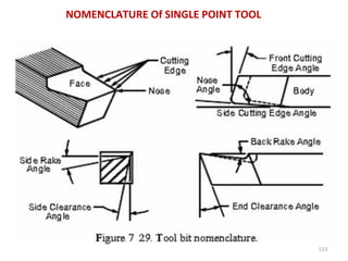
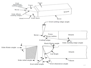
Geometry comprises mainlyof nose, rake face of the tool, flank, heel and shank etc.
The nose is shaped as conical with different angles.
107.
107
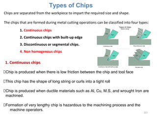
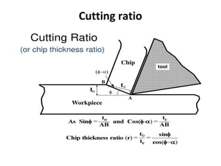
Types of Chips
Chipsare separated from the workpiece to impart the required size and shape.
The chips that are formed during metal cutting operations can be classified into four types:
1. Continuous chips
2. Continuous chips with built-up edge
3. Discontinuous or segmental chips.
4. Non homogenous chips
1. Continuous chips
Chip is produced when there is low friction between the chip and tool face
This chip has the shape of long string or curls into a tight roll
Chip is produced when ductile materials such as Al, Cu, M.S, and wrought Iron are
machined.
Formation of very lengthy chip is hazardous to the machining process and the
machine operators.
108.
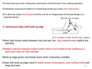
108
It may wrapup on the cutting tool, work piece and interrupt in the cutting operation.
It becomes necessary to deform or break long continuous chips into small pieces.
It is done by using chip breakers and this can be an integral part of the tool design or a
separate device.
2. Continuous chips with built-up edge
When high friction exists between chip and tool, the chip material welds itself to the
tool face.
Welded material increases friction further which in turn leads to the building up a
layer upon layer of chip material.
Build up edge grows and breaks down when it becomes unstable.
Chips with build up edge result in higher power consumption, poor surface finish and
large tool wear
109.
109
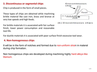
3. Discontinuous orsegmental chips
Chip is produced in the form of small pieces.
These types of chips are obtained while machining
brittle material like cast iron, brass and bronze at
very low speeds and high feeds.
For brittle materials it is associated with fair surface
finish, lower power consumption and reasonable
tool life.
For ductile materials it is associated with poor surface finish excessive tool wear.
4. Non-homogeneous chips
It will be in the form of notches and formed due to non-uniform strain in materal
during chip formation.
Non homogenous chips are developed during machining highly hard alloys like
titanium.
110.
110
Chip Control andChip Breakers
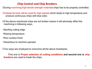
During machining high tensile strength materials chips has to be properly controlled.
Carbide tip tools will be used for high speeds which leads to high temperature and
produce continuous chips with blue color.
If the above mentioned chips are not broken means it will adversely effect the
machining in following ways,
•Spoiling cutting edge
•Raising temperature
•Poor surface finish
•Hazardous to machine operator
Two ways are employed to overcome all the above drawbacks.
First one is Proper selection of cutting conditions and second one is chip
breakers are used to break the chips.
111.
111
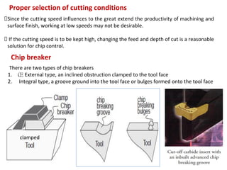
Proper selection ofcutting conditions
Since the cutting speed influences to the great extend the productivity of machining and
surface finish, working at low speeds may not be desirable.
If the cutting speed is to be kept high, changing the feed and depth of cut is a reasonable
solution for chip control.
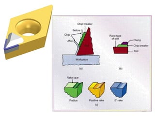
Chip breaker
There are two types of chip breakers
1. ΠExternal type, an inclined obstruction clamped to the tool face
2. Integral type, a groove ground into the tool face or bulges formed onto the tool face
clamped
115
Feed
Back rake angle(αb
)
It is the angle between the face of the tool and a line parallel with base of the tool
measured in a perpendicular plane through the side cutting edge.
This angle helps in removing the chips away from the work piece.
116.
116
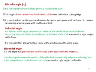
Side rake angle(αs
)
It is the angle by which the face of tool is inclined side ways.
This angle of tool determines the thickness of the tool behind the cutting edge.
It is provided on tool to provide clearance between work piece and tool so as to prevent
the rubbing of work- piece with end flank of tool.
End relief angle
It is defined as the angle between the portion of the end flank immediately below
the cutting edge and a line perpendicular to the base of the tool, measured at right angles
to the flank.
It is the angle that allows the tool to cut without rubbing on the work- piece.
Side relief angle
It is the angle that prevents the interference as the tool enters the material.
It is the angle between the portion of the side flank immediately below the side edge and
a line perpendicular to the base of the tool measured at right angles to the side.
117.
117
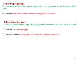
End cutting edgeangle
It is the angle between the end cutting edge and a line perpendicular to the shank of the
tool.
It provides clearance between tool cutting edge and work piece.
Side cutting edge angle
It is the angle between straight cutting edge on the side of tool and the side of the shank.
It is also known as lead angle.
It is responsible for turning the chip away from the finished surface.
118.
118
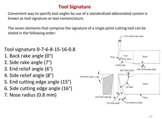
Tool Signature
Convenient wayto specify tool angles by use of a standardized abbreviated system is
known as tool signature or tool nomenclature.
The seven elements that comprise the signature of a single point cutting tool can be
stated in the following order:
Tool signature 0-7-6-8-15-16-0.8
1. Back rake angle (0°)
2. Side rake angle (7°)
3. End relief angle (6°)
4. Side relief angle (8°)
5. End cutting edge angle (15°)
6. Side cutting edge angle (16°)
7. Nose radius (0.8 mm)
119.
119
Properties of cuttingtool materials
1. Red hardness or Hot Hardness: It is the ability of a material to retain its hardness
at high temperature
2. Wear resistance: It enables the cutting tool to retain its shape and cutting efficiency
3. Toughness: It relates to the ability of a material to resist shock or impact loads
associated with interrupted cuts
Classification tool materials
1. Carbon-Tool Steels:
0.6-1.5% carbon + little amount of Mn, Si, Cr, V to increase hardness.
Low carbon varieties possess good toughness & shock resistance.
High carbon varieties possess good abrasion resistance
2. High Speed Steels (HSS):
High carbon+ little amount Tungsten, Molybdenum, Cr, V & cobalt to increase
hardness, toughness and wear résistance.
High operating temperatures upto 600o
C.
120.
120
Two types ofHSS i.e, is T-type and M-Type
Vanadium increases abrasion resistance but higher percentage will decreases
grindability.
Chromium increases hardenability
Cobalt is added to HSS to increase red hardness.
3. Cast Cobalt Base Alloys:
It is a combination of W, Cr, carbon and Cobalt which form an alloy with red
hardness, wear resistance and toughness. It is prepare by casting.
Used for machining Cast iron, alloy steels, non-ferrous metals and super alloys
4. Cemented Carbides:
These are carbides of W, Titanium and tantalum with small amount of cobalt
produced by means of powder metallurgy route.
Two types i.e, Straight Tungsten Carbide Cobalt Grade and Alloyed Tungsten
Carbide Grade
121.
121
Straight Tungsten CarbideCobalt Grade : Cast iron, non ferrous alloys, plastics, wood,
glass etc.
Alloyed Tungsten Carbide Grade: All grades of steel at 3 to 4 times more speeds than
HSS
5. Ceramic Tools:
Aluminium Oxide, Silicon Carbide, Boron Carbide, Titanium Carbide, Titanium
Boride
High speed, longer tool life, superior surface finish, No coolant is required.
6. Diamond Tools:
More abrasion resistance
Used for turning grinding wheels
Used to produce mirror surface finish.
Diamond abrassive belts are used to produce TV screens
Poly crystalline diamond inserts are brazed into cutting edges of circular saws for
cutting construction materials like concrete, refractories, stone etc.
122.
122
Tool Life
❑Properly designedcutting tool is expected to perform the metal cutting operation in
an effective an smooth manner
❑If a tool is not giving satisfactory performance it is an indicative of tool failure.
❑Following are the adverse effects observed during operation;
❑During operation cutting tool may fail due to following;
Extremely poor surface finish on the workpiece
Higher consumption of power
Work dimensions are not produced as specified
Overheating of cutting tool
Appearance of burnishing band on the work surface
Thermal cracking and softening
Mechanical Chipping
Gradual wear
123.
123
1.Thermal Cracking andSoftening
During cutting operation lot of heat will be generated due to this cutting tool tip
and area closer to cutting edge will become hot.
Cutting tool material will be harder up to certain limit (temperature & pressure), if
it crosses the limit it starts deforming plastically at tip and adjacent to the cutting
edge under the action of cutting pressure and high temperature.
Tool looses its cutting ability and it is said to have failed due to softening.
Main factors responsible for this condition are;
▪High cutting speed
▪High feed rate
▪More depth of cut
▪Small nose radius
▪Choice of wrong tool material
Tool life is defined as the time interval for which tool works satisfactorily between
two successive grinding or re-sharpening of the tool.
124.
124
Working temperatures forcommon tool materials are;
Carbon tool steels 200o
C - 250o
C
High speed steel 560o
C - 600o
C
Cemented Carbides 800o
C - 1000o
C
Tool material is subjected to local expansion and contraction due to severe
temperature gradient.
Gives rise to thermal stresses further leads to thermal cracks.
125.
125
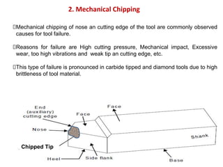
2. Mechanical Chipping
Mechanicalchipping of nose an cutting edge of the tool are commonly observed
causes for tool failure.
Reasons for failure are High cutting pressure, Mechanical impact, Excessive
wear, too high vibrations and weak tip an cutting edge, etc.
This type of failure is pronounced in carbide tipped and diamond tools due to high
brittleness of tool material.
Chipped Tip
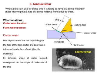
126.
126
3. Gradual wear
Whena tool is in use for some time it is found to have lost some weight or
mass implying that it has lost some material from it due to wear.
Wear locations:
Crater wear location
Flank wear location
Crater wear
Due to pressure of the hot chip sliding up
the face of the tool, crater or a depression
is formed on the face of tool. (Ductile
materials)
By diffusion shape of crater formed
corresponds to the shape of underside of
the chip
Crater wear
127.
127
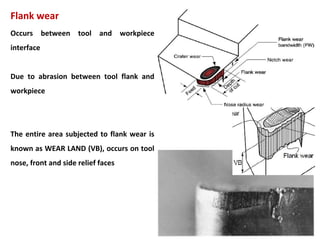
Flank wear
Occurs betweentool and workpiece
interface
Due to abrasion between tool flank and
workpiece
The entire area subjected to flank wear is
known as WEAR LAND (VB), occurs on tool
nose, front and side relief faces
128.
Machinability
The major factorinvolved in metal cutting are,
Forces and power absorbed
Tool wear and tool life
Surface finish
Dimensional accuracy
Machining cost
This factor depend upon a large variables, such as
Property of work material
Tool geometry
Cutting condition
Machine tool rigidity
128
129.
Qualitative measure ofmachinability
1. The easy with which it could be machined,
2. The life of tool before tool failure or re
sharpening
3. The quality of machined surface.
4. The power consumption per unit volume of
material removed.
129
130.
The machinability maybe evaluated as given below
• Long tool life at a given cutting speed
• Low power consumption per unit volume of
material removed.
• Maximum metal removal per tool re sharpening
• High quality of surface finish
• Good and uniform dimensional accuracy of
successive parts
• Easy disposable chips.
130
131.
131
Cutting Fluids—Types andApplications
Cutting Fluids
Essential in metal-cutting operations to reduce heat and friction
Centuries ago, water used on grindstones
100 years ago, tallow used (did not cool)
Lard oils came later but turned rancid
Early 20th
century saw soap added to water
Soluble oils came in 1936
Chemical cutting fluids introduced in 1944
132.
132
Cutting fluid isa type of coolant and lubricant designed specifically for metalworking and
machining processes.
There are various kinds of cutting fluids, which include oils, oil-water emulsions, pastes, gels
and other gases.
They may be made from petroleum distillates, animal fats, plant oils, water and other raw
ingredients.
Depending on context, type of cutting fluid is being considered, it may be referred to as
cutting fluid, cutting oil, cutting compound, coolant, or lubricant.
What is Cutting Fluid ?
133.
133
Economic Advantages toUsing Cutting Fluids
Reduction of tool costs
Reduce tool wear, tools life longer
Increased speed of production
Reduce heat and friction so higher cutting speeds
Reduction of labor costs
Tools life longer and require less regrinding, less downtime, reducing cost
per part
Reduction of power costs
Friction reduced so less power required by machining
134.
134
Characteristics of aGood Cutting Fluid
Good cooling capacity
Good lubricating qualities
Relatively low viscosity
Stability (long life)
Rust resistance
Nontoxic
Transparent
Nonflammable
135.
135
Types of CuttingFluids
⚫ Most commonly used cutting fluids
⚫ Either aqueous based solutions or cutting oils
⚫ Three categories
⚫ Cutting oils
⚫ Emulsifiable oils
⚫ Chemical (synthetic) cutting fluids


![5. The Carbonyl Process
• This method is based on the fact that metals can react with CO to
form carbonyls
• When iron and nickel ores react under high pressure (70 – 300
atm.) with carbon monoxide, iron pentacarbonyl [Fe(CO)5] or
nickel tetracarbonyl [Ni(CO)4] is formed, respectively.
• Both compounds are liquids at room temperature.
• The liquid carbonyles are stored under pressure in tanks
submerged in water.
• The distilled and filtered liquids are conveyed to steam heating
cylinders, where they are vaporized.](https://image.slidesharecdn.com/module1-250505080332-19a5f250/85/Advanced-manufacturing-engineering-non-conventional-machining-47-320.jpg)