The document describes a proposed mobile application for an electronic bus ticketing system. The proposed system would allow passengers to purchase tickets using a smartphone app and store tickets digitally. It would also allow ticket checkers to validate tickets digitally by searching the ticket number in a database. The system aims to address issues with the current manual ticketing system, such as time wasted purchasing paper tickets and the risk of losing tickets. It also outlines the design of the proposed system, including its system architecture, data flow diagram, and class diagram. The technical specifications, advantages, and limitations of the system are also discussed.
2. International Journal of Trend in Scientific Research and Development (IJTSRD) @ www.ijtsrd.com eISSN: 2456-6470
@ IJTSRD | Unique Paper ID - IJTSRD23927 | Volume – 3 | Issue – 4 | May-Jun 2019 Page: 753
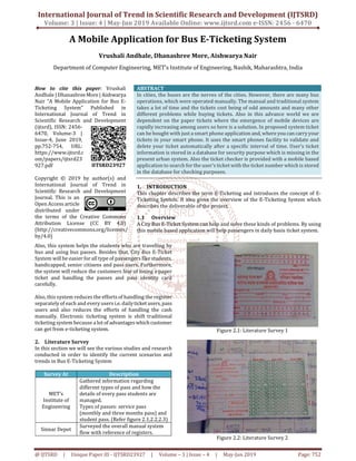
Figure 2.3: Literature Survey 3
3. Problem Definition
Our proposed system is being designed to solve theproblem
of using traditional E-Ticketing system and there are many
problems such as use of paper tickets, handling the pass and
identity card carefully, handling the cash manually and
maintaining of the records manually.
4. Design
In this Section explains the architecture of the system. We
have also describe the Data Flow Diagram which explains
flow of the project.
4.1 System Architecture
In the current scenario, there are the various hardware
platforms available as shown above. Above these the
Operating Systems reside. The application programming
interfaces are above the Operating Systems and provide the
interaction between the applications built on them and the
underlying Operating System and the Hardware Platform.
Figure 4.1: Bus E-Ticket System Architecture
4.2 Operating Environment
An operating system (OS) is a set of programs that manages
computer hard-ware resources, and provides common
services for application software. The operating system is
the most important type of system software in a computer
system. Without an operating system, a user cannot run an
application program on their computer, unless the
application program is self-booting. An Application
Programming Interface (API) is a particular set of rules
(code) and specifications that software programs canfollow
to communicate with each other.It serves as an interface
between different software programs and facilitates their
interaction, similar to the way the user interface facilitates
interaction between humans and computers. An API can be
created for applications, libraries, operating systems, etc., as
a way of defining their vocabularies and resources request
conventions (e.g. function-calling conventions). It may
include specifications for routines, data structures, object
classes, and protocols used to communicate between the
consumer program and theimplementerprogramofthe API.
4.3 Data Flow Diagram
A data flow diagram (DFD) maps out the flow of information
for any process or system. It uses defined symbols like
rectangles, circles and arrows, plus short textlabels, toshow
data inputs, outputs, storage points and the routes between
each destination.
Data flowcharts can range from simple, even hand-drawn
process overviews, to in-depth, multi-level DFDs that dig
progressively deeper into how the data is handled. They can
be used to analyze an existing system or model a new one.
While a DFD illustrates how data flows through a system,
UML is a modeling language used in Object Oriented
Software Design to provide a more detailed view.ADFDmay
still provide a good starting point, but when actually
developing the system, developers may turn to UML
diagrams such as class diagrams and structure diagrams to
achieve the required specificity.4.3.1DFD Level 0
DFD Level 0 is also called a Context Diagram. It’s a basic
overview of the whole system or process being analyzed or
modeled. Its designed to be an at-a-glance view, showingthe
system as a single high-level process, with its relationshipto
external entities. It should be easily understood by a wide
audience, including stakeholders, business analysts, data
analysts and developers.
Figure 4.3: DFD Level 0
5. Modeling
This section includes the modeling technique which
describes the Bus E-Ticketing System. It also describes the
functionality of the different features of the Bus E-Ticketing
System.
5.1 Class Diagram
The class diagram shows the building blocks of any object
oriented system. Class diagram depicts a static view of the
3. International Journal of Trend in Scientific Research and Development (IJTSRD) @ www.ijtsrd.com eISSN: 2456-6470
@ IJTSRD | Unique Paper ID - IJTSRD23927 | Volume – 3 | Issue – 4 | May-Jun 2019 Page: 754
model or part of the model, describing what attributes and
behavior it has rather that the detailing the methods of
achieving operations. Class diagrams are most useful in
illustrating relationships between classes and interfaces.
Generalizations, aggregations, and associations are all
valuable in reflecting interface, composition or usage and
connections respectively.
Figure 5.1: Class Diagram
6. Technical Specifications
6.1 Advantages
1. The effective way of transaction using in this system
make payment easy and safe.
2. Making digitalized ticket and making digital identity
card and pass for all type of pass users.
3. Time Saving.
6.2 Limitations
1. Internet is required for overall purpose of the system.
2. Not able to track the location of passenger while
entering into the bus.
6.3 Hardware Requirements
4GB RAM minimum, 8GB RAM recommended
Disk space: 2GB min
1.5GB for android SDK and Emulator system image
500MB for IDE
6.4 Software Requirements
Android Studio
Wampserver 64 bit (PHP version 7.0 and MySQL
Version 5.7.21)
JSON and PHP
Adobe Dreamweaver CC 2015 Portable
7. Conclusion
The main and important aspect of this system is to change
the overall scenario of the traditional or manual bus e-
ticketing system. This system mainly focuses on the social
issue of people who are facing the problem of travelling in
day to day life. Searching and retrieving of records would be
easier since there would be a searchmodulethatwould filter
all the needed records. Having a search module will lessen
the time of looking for records that is done manually on the
existing system. There are many aspects still to be assessed
regarding the implementation of an online ticketing system
in a bus depot, with special attention to the routines and
facilities that the new system brings to the operational
management of the whole depot system.
We believe that the methodological procedure described in
this project can contribute for minimizingpossibleproblems
faced by bus depot in the process of moving from a
conductor fare collection to an automated one. It should
finally be highlighted that under the regulation, competition,
planning, management and operation perspectives for the
bus depot, Bus E-Ticket systems will probably facilitate and
subsidize the decision making process. The Bus E-Ticket
System should make easier bus depot process.