Microcontroller-Based Intelligent Blood Collection System
•
1 like•401 views

In Hospitals Blood Plays major role, so to collect blood doctor has to conduct blood camps. To this blood camps we need more number of equipment and heavy man power. This paper mainly introduces a system to collect blood automatically and also reduce the manpower and time. In this system microcontroller is used to control all the equipment like RFID, BP Sensor, DC motor and fingerprint scanner. Here RFID is used to collect donor details of health condition to avoid accident like HIV etc. BP Sensor will sense the blood pressure in digital value. In this paper DC motor used to collect blood and Fingerprint is for doctor authentication. Finally by internetworking we can collect the blood.

Recommended
Recommended
More Related Content
What's hot
What's hot (20)
Viewers also liked
Viewers also liked (16)
Similar to Microcontroller-Based Intelligent Blood Collection System
Similar to Microcontroller-Based Intelligent Blood Collection System (20)
More from ijsrd.com
More from ijsrd.com (20)
Recently uploaded
Recently uploaded (20)
Microcontroller-Based Intelligent Blood Collection System
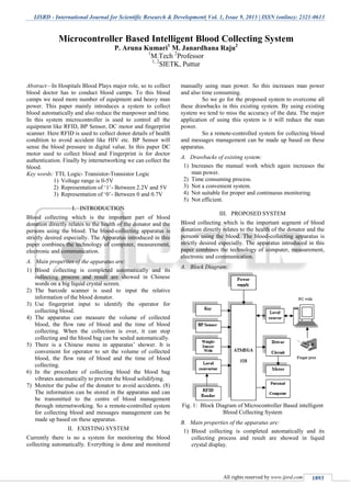
- 1. IJSRD - International Journal for Scientific Research & Development| Vol. 1, Issue 9, 2013 | ISSN (online): 2321-0613 All rights reserved by www.ijsrd.com 1893 Abstract—In Hospitals Blood Plays major role, so to collect blood doctor has to conduct blood camps. To this blood camps we need more number of equipment and heavy man power. This paper mainly introduces a system to collect blood automatically and also reduce the manpower and time. In this system microcontroller is used to control all the equipment like RFID, BP Sensor, DC motor and fingerprint scanner. Here RFID is used to collect donor details of health condition to avoid accident like HIV etc. BP Sensor will sense the blood pressure in digital value. In this paper DC motor used to collect blood and Fingerprint is for doctor authentication. Finally by internetworking we can collect the blood. Key words: TTL Logic- Transistor-Transistor Logic 1) Voltage range is 0-5V 2) Representation of ‘1’- Between 2.2V and 5V 3) Representation of ‘0’- Between 0 and 0.7V I. INTRODUCTION Blood collecting which is the important part of blood donation directly relates to the health of the donator and the persons using the blood. The blood-collecting apparatus is strictly desired especially. The Apparatus introduced in this paper combines the technology of computer, measurement, electronic and communication. A. Main properties of the apparatus are: 1) Blood collecting is completed automatically and its collecting process and result are showed in Chinese words on a big liquid crystal screen. 2) The barcode scanner is used to input the relative information of the blood donator. 3) Use fingerprint input to identify the operator for collecting blood. 4) The apparatus can measure the volume of collected blood, the flow rate of blood and the time of blood collecting. When the collection is over, it can stop collecting and the blood bag can be sealed automatically. 5) There is a Chinese menu in apparatus’ shower. It is convenient for operator to set the volume of collected blood, the flow rate of blood and the time of blood collecting. 6) In the procedure of collecting blood the blood bag vibrates automatically to prevent the blood solidifying. 7) Monitor the pulse of the donator to avoid accidents. (8) The information can be stored in the apparatus and can be transmitted to the centre of blood management through internetworking. So a remote-controlled system for collecting blood and messages management can be made up based on these apparatus. II. EXISTING SYSTEM Currently there is no a system for monitoring the blood collecting automatically. Everything is done and monitored manually using man power. So this increases man power and also time consuming. So we go for the proposed system to overcome all these drawbacks in this existing system. By using existing system we tend to miss the accuracy of the data. The major application of using this system is it will reduce the man power. So a remote-controlled system for collecting blood and messages management can be made up based on these apparatus. A. Drawbacks of existing system: 1) Increases the manual work which again increases the man power. 2) Time consuming process. 3) Not a convenient system. 4) Not suitable for proper and continuous monitoring. 5) Not efficient. III. PROPOSED SYSTEM Blood collecting which is the important segment of blood donation directly relates to the health of the donator and the persons using the blood. The blood-collecting apparatus is strictly desired especially. The apparatus introduced in this paper combines the technology of computer, measurement, electronic and communication. A. Block Diagram: Fig. 1: Block Diagram of Microcontroller Based intelligent Blood Collecting System B. Main properties of the apparatus are: 1) Blood collecting is completed automatically and its collecting process and result are showed in liquid crystal display. Microcontroller Based Intelligent Blood Collecting System P. Aruna Kumari1 M. Janardhana Raju2 1 M.Tech 2 Professor 1, 2 SIETK, Puttur
- 2. Microcontroller Based Intelligent Blood Collecting System (IJSRD/Vol. 1/Issue 9/2013/0050) All rights reserved by www.ijsrd.com 1894 2) The RFID reader is used to input the relative information of the blood donator. 3) Use fingerprint input to identify the operator for collecting blood the apparatus can measure collected blood. (4) Monitor the pulse of the donator to avoid accidents using BP sensor. In this project, the fingerprint scanner is used to identify the operator for collecting blood and RFID reader is used to identify the donator information to get from RFID tag and given information to ARM processor. The BP sensor is used to check blood pressure of donator. If BP is normal only blood will be collected from donator, blood collecting key is on to collect the blood , the blood is collected from patient as well as monitoring donator BP condition and level of blood collecting apparatus using weight sensor. ARM processor stops Collection blood immediately either any abnormalities in BP value or collection apparatus is filled using sensed by weight sensor. The blood collecting apparatus is strictly desired especially. In this project, the fingerprint scanner is used to identify the operator for collecting blood and RFID reader is used to identify the donator information to get from RFID tag and given information to ARM 7 processor. IV. HARDWARE AND SOFTWARE REQUIREMENTS A. HARDWARE REQUIREMENTS: The world’s most efficient 32-bit microcontroller. The 32- bit AVR UC3 microcontroller takes efficiency to a new level, going beyond high performance and low power consumption. Native fixed point DSP support, dual port SRAM, multi-layer data bus, peripheral DMA controller, peripheral event system and intelligent peripherals move performance and power consumption to the next step. B. Pin diagram for ATMEGA328: Fig. 2: Pin diagram The peripheral DMA controller and multi-layer high-speed bus architecture make the UC3 microcontrollers ideal for high throughput applications. Intelligent peripherals and dynamic power control make UC3 devices the obvious choice for portable and battery-powered applications. Selected UC3 devices include an integrated floating point unit (FPU) which improves arithmetic performance on decimal numbers, with better precision and wider dynamic range. For sensor fusion processing applications, UC3L devices can work with your own sensor fusion code and sensors provided by our extensive range of partners. Fig. 2: Pin diagram for ATMEGA328 C. Key Features: 1) Connectivity: USB device and host, Ethernet MAC, SDRAM, NAND flash, and fast serial interfaces are ideal for complex applications. 2) Arithmetic performance: Integrated FPU increases precision and dynamic range in digital signal processing. 3) High data throughput: Peripheral DMA, multi-layered data bus and large on-chip SRAM remove bottlenecks in high-speed communication. 4) Low power consumption: picoPower® technology delivers the industry's lowest power consumption in active and sleep modes. 5) Software Library: All UC3 devices are supported by AVR Software Framework, a complete library of device drivers and middleware. D. RF ID Tag and RF Reader: An RFID tag is a microchip combined with an antenna in a compact package; the packaging is structured to allow the RFID tag to be attached to an object to be tracked. "RFID" stands for Radio Frequency Identification. The tag's antenna picks up signals from an RFID reader or scanner and then returns the signal, usually with some additional data (like a unique serial number or other customized information). RFID tags can be very small - the size of a large rice grain. Others may be the size of a small paperback book. An RFID reader is a device that is used to interrogate an RFID tag. The reader has an antenna that emits radio waves; the tag responds by sending back its data. A number of factors can affect the distance at which a tag can be read (the read range). The frequency used for identification, the antenna
- 3. Microcontroller Based Intelligent Blood Collecting System (IJSRD/Vol. 1/Issue 9/2013/0050) All rights reserved by www.ijsrd.com 1895 gain, the orientation and polarization of the reader antenna and the transponder antenna, as well as the placement of the tag on the object to be identified will all have an impact on the RFID system’s read range. We use RFID module for authentication purpose of the blood donor. 1) Fingerprint Scanner: Fingerprint recognition or fingerprint authentication refers to the automated method of verifying a match between two human fingerprints. Fingerprints are one of many forms of biometrics used to identify individuals and verify their identity. This article touches on two major classes of algorithms (minutia and pattern) and four 2) Keypad: A keypad is a set of buttons arranged in a block or "pad" which usually bear digits, symbols and usually a complete set of alphabetical letters. If it mostly contains numbers then it can also be called a numeric keypad. 3) BP Sensor: It is used to measure the blood pressure of a patient. Produce voltage level for corresponding Blood pressure level. 4) Weight sensor: It is used to measure the weight of the desired the blood which needs to be collected. Voltage is produced for appropriate weight. V. SOFTWARE REQUIREMENTS A. Embedded C: This is for people who already know how to program desktop computers and now wish to develop software for embedded systems. In this introductory chapter, we consider some important decisions that must be made at the start of any embedded project: 1) The choice of processor. 2) The choice of programming language. 3) The choice of operating system. 4) We begin by considering the meaning of the phrase ‘embedded system’. B. Programming embedded systems in C: An embedded system is an application that contains at least one programmable computer (typically in the form of a microcontroller, a microprocessor or digital signal processor chip) and which is used by individuals who are, in the main, unaware that the system is computer-based. C. Arduino Compiler: Arduino is a tool for making computers that can sense and control more of the physical world than your desktop computer. It's an open-source physical computing platform based on a simple microcontroller board, and a development environment for writing software for the board. Arduino can be used to develop interactive objects, taking inputs from a variety of switches or sensors, and controlling a variety of lights, motors, and other physical outputs. Arduino projects can be stand-alone, or they can be communicating with software running on your computer (e.g. Flash, Processing, and MaxMSP.) The boards can be assembled by hand or purchased preassembled; the open- source IDE can be downloaded for free. The Arduino programming language is an implementation of Wiring, a similar physical computing platform, which is based on the Processing multimedia programming environment. There are many other microcontrollers and microcontroller platforms available for physical computing. Parallax Basic Stamp, Netmedia's BX-24, Phidgets, MIT's Handy board, and many others offer similar functionality. All of these tools take the messy details of microcontroller programming and wrap it up in an easy-to-use package. Arduino also simplifies the process of working with microcontrollers, but it offers some advantage for teachers, students, and interested amateurs over other systems: 1) Inexpensive - Arduino boards are relatively inexpensive compared to other microcontroller platforms. The least expensive version of the Arduino module can be assembled by hand, and even the pre-assembled Arduino modules cost less than $50 2) Cross-platform - The Arduino software runs on Windows, Macintosh OSX, and Linux operating systems. Most microcontroller systems are limited to Windows. 3) Simple, clear programming environment - The Arduino programming environment is easy-to-use for beginners, yet flexible enough for advanced users to take advantage of as well. For teachers, it's conveniently based on the Processing programming environment, so students learning to program in that environment will be familiar with the look and feel of Arduino 4) Open source and extensible software- The Arduino software is published as open source tools, available for extension by experienced programmers. The language can be expanded through C++ libraries, and people wanting to understand the technical details can make the leap from Arduino to the AVR-C programming language on which it's based. Similarly, you can add AVR-C code directly into your Arduino programs if you want to. 5) Open source and extensible hardware - The Arduino is based on Atmel's ATMEGA328 microcontrollers. The plans for the modules are published under a Creative Commons license, so experienced circuit designers can make their own version of the module, extending it and improving it. Even relative in experienced users can build the breadboard version of the module in order to understand how it works and save money. D. Dot Net: Dot Net is basically a programming framework created by Microsoft. It is intended to use only in the Windows platform. It includes a large library of pre-coded solutions to common programming problems and a virtual machine that manages the execution of programs written specifically for the frame work. Programs written for the .NET Framework execute in a software environment that manages the program's runtime requirements. We use Dot Net Frame work at the back end to display and manage the outputs of the entire system and maintain a database of the obtained outputs. VI. COMPARISON OF PROPOSED AND EXISTING SYSTEM Existing System Proposed System Increases the manual Every operation is done by
- 4. Microcontroller Based Intelligent Blood Collecting System (IJSRD/Vol. 1/Issue 9/2013/0050) All rights reserved by www.ijsrd.com 1896 operation the microcontroller so need for manual operation. Not possible to get the accurate ml of blood from the blood donator It is possible to get the accurate ml of blood from the blood Not efficient and flexible to use in all the places. Efficient and proper system for continuous Monitoring Not portable and not convenient Portable and convenient. A. APPLICATION: In hospital this system can be used to collect the blood from the blood donator and get the data of blood donator and as well as to get the data of the boll collector is possible using this system. In blood collecting camps these systems can be used to monitor the blood collection and to ensure the fast process. B. RS232 Logic: 1) VOLTAGE RANGE IS -25V TO +25V 2) REPRESENTATION OF ‘1’- BETWEEN -25V AND -3V 3) REPRESENTATION OF ‘0’- BETWEEN +3V AND +25V C. RFID Tag and Reader: 1) Type- Passive (No Power Source is available) and Active (With power source, Example- Battery) 2) Power Source for Passive tag- Inductive or Radioactive Coupling is employed 3) Frequency Range- Frequencies of 125/134 KHz (LF) or 13.56 MHz (HF) is used. 4) We use Passive RFID Tag with a frequency of 125 KHz VII. FUTURE ENHANCEMENT The system can be expanded in future by increasing the number of sensors to measure the other parameters of the body to make this an more suitable and appropriate one for blood collecting and for other health care purposes. VIII. EXPERIMENTAL RESULTS Using this apparatus we can collect the blood automatically by reducing the man power. Here this apparatus is operated by Arduino Software. A. When the apparatus is connected to PC using Max232 cable and power is given B. When the apparatus is connected if the donor is valid then it will ask for measuring Blood Pressure C. If BP is normal then we are going to collect the blood shown below By using weight sensor we going to collect accurate ml of blood and finally fingerprint authentication for doctor is to collect blood D. Figure shown is the image representation of fingerprint E. Comparing with enrolled image if the previous image is matched with enrolled image then it will give message to collect blood.
- 5. Microcontroller Based Intelligent Blood Collecting System (IJSRD/Vol. 1/Issue 9/2013/0050) All rights reserved by www.ijsrd.com 1897 F. Finally collecting the blood with given safety precautions IX. CONCLUSION The automatic collect-blood apparatus uses the advanced technology of MCU, fingerprint identifying and barcode. So the degree of the automation is enhanced greatly. It controls the operator of collect-blood strictly to prevent the errors caused by man. It strengthens the scientific management of the message of the blood donator and the collected blood to prove the safety of the blood collecting. This apparatus makes automatic collect-blood and high reliability come true and lay a foundation for automatic management of blood. A remote-controlled system for collecting blood and messages management can be made up based on these apparatus. A. Advantages of Proposed System: 1) Can get the accurate ml of blood from the blood donator. 2) Efficient and suitable for continuous monitoring. 3) Low cost and less time consuming 4) Secured and portable. REFERENCES [1] Pan Zuojin, Shi Guojun Principle of C8051FXXX High Speed SOC and its Application, 2002. [2] Atmel Corporation. AT29C256, 2002. [3] Atmel Corporation. AT29 Flash memories, 1998. [4] Veridicom Inc. Solid-state Fingerprint Sensor, 1998. [5] Douglas E. Comer. Internetworking With TCP/IP Vol I: Principles, Protocols, and Architecture, Third Edition [M]. Qinghua University Press, 1998. [6] M. Tim Jones. TCP/IP Application Layer Protocols for Embedded Systems [M]. Electronic Industry Press, 2003. [7] W3100A technical datasheet v1.1.