Igbt based on vector control of induction motor drive
•
1 like•454 views

IJRET : International Journal of Research in Engineering and Technology is an international peer reviewed, online journal published by eSAT Publishing House for the enhancement of research in various disciplines of Engineering and Technology. The aim and scope of the journal is to provide an academic medium and an important reference for the advancement and dissemination of research results that support high-level learning, teaching and research in the fields of Engineering and Technology. We bring together Scientists, Academician, Field Engineers, Scholars and Students of related fields of Engineering and Technology

Recommended
Recommended
More Related Content
What's hot
What's hot (20)
Viewers also liked
Viewers also liked (20)
Similar to Igbt based on vector control of induction motor drive
Similar to Igbt based on vector control of induction motor drive (20)
More from eSAT Publishing House
More from eSAT Publishing House (20)
Recently uploaded
Recently uploaded (20)
Igbt based on vector control of induction motor drive
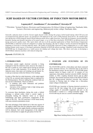
- 1. IJRET: International Journal of Research in Engineering and Technology eISSN: 2319-1163 | pISSN: 2321-7308 __________________________________________________________________________________________ Volume: 03 Issue: 02 | Feb-2014, Available @ http://www.ijret.org 20 IGBT BASED ON VECTOR CONTROL OF INDUCTION MOTOR DRIVE Loganayaki.N1 , Anandkumar.V2 , Jeevananthan.S3 , Kowsalya.M4 1, 4 PGscholar, 2 Assitant Professor, Electronics and Communication, Sri Eshwar College of engineering, Tamilnadu, India, 3 Lecturer, Electronics and engineering, Maharani poly technic college, Tamilnadu, India, Abstract Generally, induction motor is fed by Current supply Inverter (CSI). During this project, hybrid model during which CSI area unit accustomed feed the induction motor, are introduced. CSI employed in this work is SCR primarily based device. the standard gate turn-off thyristor (GTO) primarily based CSI-fed induction motor drives suffer from draw- backs like low-frequency torsion pulsation, harmonic heating and unstable operation at low-speed ranges. so as to beat these drawbacks, STATCOM is an efficient answer for facing such power quality issues. This report deals with one in all the potential applications of Static Synchronous Compensator (STATCOM) to industrial systems for mitigation of voltage dip drawback. The dip in voltage is mostly encountered throughout the beginning of Associate in nursing induction motor. The model of STATCOM connected in shunt configuration to a 3 part supply feeding dynamic motor masses is developed exploitation Simulink of MATLAB software package. Simulated results demonstrate that STATCOM may be thought-about as a viable answer for finding such voltage dip issues. This thesis work aims at developing a STATCOM for induction machines with reduced voltage dip. Keywords: STATCOM, CSI, -----------------------------------------------------------------------***----------------------------------------------------------------------- 1. INTRODUCTION Now-a-days current supply electrical converter is being employed to feed the induction motor. however the output of the CSI is similar sq. wave output and it's having an outsized quantity of low order harmonics. If it's directly fed to the induction motor, then stator coil windings can get heated. So, it ends up in decrease within the lifetime of the windings. In order to filter that low order harmonics, at the output aspect of the CSI, an outsized rated condenser bank is employed for the filtering purpose. However adding the condenser bank can turn out lots of drawbacks. They're as follows. 1) It combines with motor inductance and produces resonance drawback. 2) And price of the condenser bank is high relying upon the rating of the capacitors To overcome these drawbacks, during this work, a hybrid technique is utilized within which a current supply is principally feeding the induction motor as in typical methodology and Static synchronous compensator at the output of the CSI. The CSI used here is SCR based mostly with none external commutation circuit. The main advantage of this hybrid sort is that once anyone of the supply is didn't feed, then the induction motor will be pass victimization another one supply thereby continuous operation will be obtained. And vector management of the induction motor is utilized here to supply the gate pulses for the CSI. 2 STATCOM AND FUNCTIONS OF ITS CONTROLLER The STATCOM could be a three-phase and shunt connected power electronic devices. it's connected close to the load at the distribution systems. the key parts of a STATCOM square measure shown in Figure a pair of.1. It consists of a dc capacitance, three-phase electrical converter (IGBT, thyristor) module, ac filter, coupling electrical device and an effect technique. the essential electronic block of the DSTATCOM is that the voltage-sourced electrical converter that converts Associate in Nursing input dc voltage into a three-phase output voltage at fundamental. STATCOM uses Associate in Nursing electrical converter to convert the DC link voltage Vdc on the capacitance to a voltage supply of correctable magnitude and part. so the STATCOM is treated as a voltage-controlled supply. The STATCOM may be seen as a current controlled supply. Fig.1 Basic building blocks of the STATCOM
- 2. IJRET: International Journal of Research in Engineering and Technology eISSN: 2319-1163 | pISSN: 2321-7308 __________________________________________________________________________________________ Volume: 03 Issue: 02 | Feb-2014, Available @ http://www.ijret.org 21 STATCOM uses Associate in Nursing electrical converter to convert the DC link voltage Vdc on the capacitance to a voltage supply of correctable magnitude and part. so the STATCOM is treated as a voltage-controlled supply. The STATCOM may be seen as a current controlled supply. The inductance L and resistance R that represents the equivalent circuit parts of the transformer and therefore the electrical converter is that the main part of the STATCOM. The voltage Vi is that the effective output voltage of the STATCOM and δ is that the power angle. The reactive power output of the STATCOM is either inductive or electrical phenomenon counting on the operation mode of the STATCOM the controller of the STATCOM is employed to work the electrical converter in such the way that the point in time between the electrical converter voltage and therefore the line voltage is dynamically adjusted so the STATCOM generates or absorbs the specified power unit at the purpose of association. The part of the output voltage of the thyristor-based electrical converter, Vi, is controlled within the same method because the distribution system voltage, Vs. Figure 2 shows the 3 basic operation modes of the STATCOM output current (I), that varies relying upon voltage Vi. If Vi is adequate to system voltage Vs, the reactive power is zero and therefore the STATCOM doesn't generate or absorb reactive power. once Vi is larger than Vs, the STATCOM acts as Associate in Nursing inductive electrical phenomenon connected at its terminal. the present, I, flows through the electrical device electrical phenomenon from the STATCOM to the ac system, and therefore the device generates electrical phenomenon reactive power. If Vs is larger than Vi, the STATCOM acts as a electrical phenomenon electrical phenomenon connected to its terminal. Then the present flows from the ac system to the STATCOM, leading to the device to soak up inductive reactive power. (a) No-Load mode (Vs=Vi) (b) Electrical phenomenon mode (Vi >Vs) (c) Inductive mode (Vi<Vs) Fig 2 Operation modes of STATCOM 2.1 Main Options Of STATCOM 1. Power issue correction. 2. Current harmonics elimination. 3. Voltage regulation and compensate of reactive power. 2.2 STATCOM Controllers 1. PI Controller 2. physical phenomenon Controller 2.2.1 Style of PI Controller PI controller is shown in Figure 3. PI controller is one among the foremost wide needed controller within the trade because it is that the simplest to style. In projected system, one PI controller is developed over the DC link voltage of
- 3. IJRET: International Journal of Research in Engineering and Technology eISSN: 2319-1163 | pISSN: 2321-7308 __________________________________________________________________________________________ Volume: 03 Issue: 02 | Feb-2014, Available @ http://www.ijret.org 22 STATCOM. The DC bus voltage is filtered then compared with the reference worth. so the ensuing error signal ( ve (n) = Vdcr - Vdc(n) ) is obtained and therefore the output Vo(n) is obtained as: Vo (n) = Vo(n-1) + Kp (Ve(n)-Ve(n-I)) + Ki Ve(n) Fig 3 PI controller 2.3 Style of Physical Phenomenon Controller Physical phenomenon controller for the trailing of reference supply currents is shown in Figure 4. The error signals of the reference and therefore the actual (instantaneous) supply currents ar calculated and compared at intervals a little physical phenomenon band that is usually one hundred and twenty fifth to5% of the present level. The management logic used is given as isa < isa* - haemoglobin, then the higher switch of VSC is turned OFF and lower switch is turned ON. The higher and therefore the lower shift device (IGBT in our model) ar switched ON and OFF during a complementary fashion. The physical phenomenon band haemoglobin is often varied. A slim physical phenomenon band ends up in superb and quick trailing of currents however shift frequency might become too high. a good physical phenomenon band might not offer effective trailing so resulting in the system turning into unstable. Fig 4 Schematic illustration of PWM physical phenomenon management 2.4 Management Theme Fig 5 Schematic diagram of STATCOM management theme Figure 5 shows the management theme for voltage regulation of the motor. Here we tend to use 2 PI controllers. One PI controller theme is accomplished over the detected and reference values of dc bus voltage of the STATCOM. The second PI controller is accomplished over the detected and reference values of ac voltage at PCC.The output of the primary PI controller (Ispdr) is taken into account as amplitude of in-phase elements of reference provide currents and therefore the output of second PI controller (Ispqr) is taken into account to be the amplitude of construction elements of reference provide currents. a collection of in- phase unit vectors (ua, ub and uc) ar calculated by dividing the terminal voltages (vta, vtb and vtc) by their amplitude (vtm). Another set of three-phase construction unit current vectors (wa, magnetic flux unit and wc) ar calculated victimization in- phase unit current vectors (ua, ub and uc) The multiplication of in-phase amplitude with in-phase unit current vectors ends up in part elements (isadr, isbdr and iscdr) of three-phase reference provide currents and equally multiplication of construction amplitude with construction unit current vectors ends up in the construction elements (isaqr, isbqr and iscqr) of three-phase reference provide currents. Algebraical total of those in-phase and construction elements leads to the three-phase reference provide currents (isar, isbr, and iscr). These three-phase reference provide currents ar calculated exploitation three-phase provide voltages and dc bus voltage of the STATCOM. 2.4.1 Computation of In-Phase Elements of Reference Provide Currents The amplitude of in-phase part of reference provide currents (Ispdr) are often calculated exploitation initial PI controller over the typical price of dc bus voltage of the STATCOM and its reference counterpart.
- 4. IJRET: International Journal of Research in Engineering and Technology eISSN: 2319-1163 | pISSN: 2321-7308 __________________________________________________________________________________________ Volume: 03 Issue: 02 | Feb-2014, Available @ http://www.ijret.org 23 Ispdr(n) = Ispdr(n-1) + Kpd+ child vde(n) (1) wherever vde(n) = vdcr- vdca(n) denotes the error in vdc calculated over reference vdcr andaverage price of vdc and Kpd and child ar proportional and integral gains of the dc bus voltage PI controller. The output of this PI controller provides the amplitude of in- phase part of the reference provide currents. 3 section elements of the reference provide currents ar computed exploitation their amplitude and in-phase unit current vectors ar derived from the availability voltages. The amplitude of the availability voltage is calculated as following: vtm2 = 2/3(vta2 + vtb2 + Vtc2) (2) The unit vectors (ua, ub, uc ) ar calculated as: ua = vta/ vtm ub = vtb/ vtm uc = American statec/ vt (3) The in-phase magnitudes of reference currents (isadr, isbdr, iscdr) ar calculated as: isadr = lspdr ua isbdr = lspdr ub iscdr= lspdruc (4) 2.4.2 Computation of construction elements of Reference provide Currents The amplitude of construction part of reference provide currents (Ispqr) is computed exploitation second PI controller over the typical values of the amplitude of provide voltage and its reference counterpart. Ispqr(n) =Ispqr(n-l) + Kpq + Kiq vae(n) (5) where vae(n)= vtmr- vtm(n) denotes the error in vtm calculated over reference vtmr and average price of Vtm and Kpq and Kiq ar the proportional and integral gains of the second PI controller. The construction unit current vectors (wa, wb, wc) ar derived from in-phase unit current vectors (ua, ub, uc) as: wa=I/ (3)1/2 wb=/ 2(3)1/2 wc=/2(3)1/2 (6) 2.4.3 Computation of Total Reference Provide Currents The overall reference currents ar calculated by the addition of various in-phase and construction current elements as: isar = isadr + isaqr isbr = isbdr + isbqr iscr = iscdr + iscqr (7) A PWM physical phenomenon controller is applied over the perceived (isa, isb and isc) and therefore the reference values of provide currents (isar, isbr and iscr) to get six gating pulses for the six IGBT switches utilized in the STATCOM. 3 LOAD COMMUTATED CURRENT SUPPLY ELECTRICAL CONVERTER In Auto-Sequential Current supply electrical converter (ASCSI), 2 commutating capacitors, beside four diodes, are used for commutation from one combine of thyristors to the second combine. So, during this projected work load commutated electrical converter is employed. Load commutation means the thyristors change by reversal by the influence of the load elicited e.m.f. unremarkably load commutated electrical converter for the induction motor is employed for the aim of power reversal i.e for regeneration method. during this work, SCR based mostly load commutated current supply electrical converter is employed. Single section load commutated electrical converter CSI is shown in Figure . Fig 6 single phase LCI 3.1 Load Commutated CSI Current supply electrical converter utilized in this projected is load commutated current supply electrical converter that is of SCR primarily based sort. ordinarily self commutating
- 5. IJRET: International Journal of Research in Engineering and Technology eISSN: 2319-1163 | pISSN: 2321-7308 __________________________________________________________________________________________ Volume: 03 Issue: 02 | Feb-2014, Available @ http://www.ijret.org 24 switches like GTO, IGBT square measure utilized in CSI. however in load commutated CSI electrical converter, thyristors square measure used with none external circuit during this project. Load commutation is outlined because the commutation or turning off of the thyristors by the influence of iatrogenic voltage within the load. The load commutation is clearly shown in figure 7 . that this through the switches attains zero before the voltage attains. Fig. 7 Undulation Of Load Commutation In this projected hybrid technique, this load commutated SCR based mostly current supply electrical converter provides the important power demand of the induction motor. The SCRs utilized in this LCI square measure commutated by operative this CSI in leading power issue. that's done attributable to the injection of reactive current into the circuit by exploitation 3 level diode clamped electrical converter that is mentioned on top of. LCI utilized in this technique is shown in figure 8. These square measure principally utilized in industrial applications for feeding the ac motor drives. Fig 8 LCI used in hybrid technique 4. PROPOSED HYBRID TECHNIQUE Normally, the output of CSI could be a similar sq. wave output with a coffee order harmonics. It can’t be directly fed to the Induction Motor. If it's directly fed thereto, then it'll turn out heat in stator coil Windings and its life time are reduced. so as to avoid this downside, in typical technique, an oversized rating condenser bank is connected at the output aspect of CSI that filters the low order harmonics and therefore it converts the similar sq. wave into part curving wave shape. But, there's plenty of downside during this technique (i.e) 1. The price of condenser bank is high, 2. That condenser combines with the motor inductance and creates resonance issues. To beat the drawbacks of typical technique, this hybrid technique [4], [5], [6] during which a STATCOM is connected at the output of the CSI, is enforced here. One Active filter used here. 4.1 Hybrid Technique Figure 9 diagram of the planned hybrid technique. In that, current supply electrical converter and STACOM square measure used. CSI is connected on to the induction motor. And STATCOM is connected to the input of the induction motor. By victimisation this method, the induction motor is operated within the leading power issue. STATCOM connected as shunt compensator. It consists of a three-phase, current controlled voltage supply device (CC-VSC) associated an electrolytic DC condenser. The DC bus condenser during this case is employed to produce a self supporting DC bus AC output terminals of the STATCOM square measure connected through filter electrical phenomenon or electrical phenomenon of the connecting electrical device STATCOM therefore provides quick and economical reactive power compensation. Fig. 9 Block diagram of the planned system STATCOMs area unit usually applied in long distance transmission systems, power substations and significant industries wherever voltage stability is that the primary concern. Additionally, static synchronous compensators area unit put in choose points within the facility to perform the following: 1. Voltage support and management 2. Voltage fluctuation and flicker mitigation 3. Unsymmetrical load equalization 4. Power issue correction 5. Active harmonics cancellation 6. Improve transient stability of the facility system
- 6. IJRET: International Journal of Research in Engineering and Technology eISSN: 2319-1163 | pISSN: 2321-7308 __________________________________________________________________________________________ Volume: 03 Issue: 02 | Feb-2014, Available @ http://www.ijret.org 25 4.2 Description of Load Commutated CSI Fed Induction Motor Drive A current supply electrical converter accepts input from an influence provide that acts as a current supply instead of a voltage supply. among some limits, a DC current supply delivers a group current to a load while not respect to the resistance of the load or the voltage needed. Most DC power sources, like generators and batteries, area unit voltage sources that deliver a group voltage to the load despite the present drawn by the load with in some limits where as a voltage supply electrical converter produces associate AC voltage by switch the input voltage to supply positive and negative voltage pulses, a current supply electrical converter produces associate AC current by switch or steering the input current to divide the present into positive and negative pulses. Current supply electrical converters are used because the inverter section of AC to AC adjustable frequency power conversion units like those used for AC motor speed management. an oversized inductance between the controlled rectifier and electrical converter sections permits the controlled rectifier to act as a current supply. The feedback circuit contains associate inner loop current regulator associated an outer loop voltage or speed regulator. Some of the benefits of the planned system area unit 1. The gate drive circuits for the thyristors area unit easy com- pared to those of the GTOs. 2. because the thyristors area unit employed in place of GTOs, in the CSI, the drive will directly feed medium-voltage dynamical motors [8]. 3. The commutation method of the thyristors within the CSI doesn't rely on the load. 4. The motor experiences curving voltage and current that overcomes the drawbacks of the PWM voltage fed adjustable speed drive like insulation failure and heating of the stator coil windings attributable to overvoltage. 5. Low frequency torsion pulsation is completely small even supposing the CSI operational is working} in six step operating mode. 6. The motor doesn't need an oversized rating electrical device bank that was needed just in case of standard methodology (i.e) in GTO primarily based CSI. 4.3 Details of System of the Planned Hybrid Scheme: The management theme for LCI-fed induction motor drive with curving voltage and curving current is accomplished through harmonic and reactive current injection by the active filter (VSI) in an exceedingly desired manner. Figure 10 shows the careful diagram of the system of the planned drive theme. The active current needed by the motor is controlled by dominant the dc link current of the LCI. so as to style such a controller, field-oriented management is utilized. Rotor flux orientation may be a natural selection for decoupling the flux and torsion manufacturing currents of the induction motor. Contrary to the sphere orientating management of a PWM VSI-fed induction motor drive, flux and torsion manufacturing currents of the induction motor don't seem to be directly controlled. Instead, the torsion manufacturing current is controlled, by dominant the dc link current of the LCI; the flux manufacturing current of the motor is controlled by dominant the reactive current injection by the active filter connected at the motor terminal. Broadly, the system of the full drive has 2 main objectives. a) Speed and torsion management of the induction motor, keeping the motor flux constant, i.e., freelance management of motor flux and torsion. b) Management of reactive current and harmonic current injection by the active filter. The main aim of this system details is to explain the subsequent. 1) Vector management or field orientating management of CSI-fed induction motor drive 2) Reactive current compensation by the active filter for eminent load commutation of the SCRs within the LCI. 3) Harmonic current compensation by the active filter (VSI) to realize curving motor current and voltage wave form. From then on top of statements, we are able to say that, the $64000 power is provided by the CSI and reactive power is provided by the VSI. and also the reactive power injection helps in load commutation of thyristors employed in CSI. Fig 10 Block diagram of the control structure of the drive scheme
- 7. IJRET: International Journal of Research in Engineering and Technology eISSN: 2319-1163 | pISSN: 2321-7308 __________________________________________________________________________________________ Volume: 03 Issue: 02 | Feb-2014, Available @ http://www.ijret.org 26 5. EXPERIMENTAL RESULTS The STATCOM controller is shown in the graph. The speed is rating is reach 1500rpm.And also controls the THD in the input voltage and current. Fig 11 Output waveform of vector control of load commutated CSI fed induction motor drive CONCLUSIONS A model of three phase source feeding motor loads has been developed using PSB and Simulink of standard MATLAB software. The size of the capacitor used is very small and operation without capacitor is also possible. Because of the presence of current loops, vector control is implemented and it is ensured that active power is always sourced by the CSI Sudden application of an induction motor load results in large starting currents which results in sudden dip in ac terminal voltage at PCC The extent of voltage dip with and without STATCOM controller is compared This voltage dip is of the order of 563% without any controller. This dip is very large and it may affect the functioning of other sensitive equipment connected at PCC Model of STATCOM system applied in shunt configuration has been developed The STATCOM control utilizes two PI controllers for regulating DC link voltage and also the ac terminal voltage at PCC The Simulated results have shown that STATCOM application reduces the momentary dip to from 563% to 407% only The voltage dip can be reduced by proper tuning of PI controllers and use of fixed value of AC capacitor. The future scope in the control method used here is vector control of induction motor. Instead of this control method, sensor less vector control can be used to improve the performance factors of inverters as well as the induction motor. And the rating of capacitor bank can be reduced by using three level current source inverter thereby we can reduce switching losses, THD and the output can be improved ACKNOWLEDGEMENTS The authors would like to thank Asst.Professor V.Anandkumar for his valuable guidance and the anonymous reviewers for their helpful comments on earlier drafts of the work. REFERENCES [1]. A. M. Trzynadlowski, N. Patriciu, F. Blaabjerg, and J. K. Pedersen, Nov. 2001, “A hybrid, current-source/voltage- source power inverter circuit,” IEEE Trans. Power Electron., vol. 16, no. 6, pp. 866–871. [2]. C. Dietrich , S. Gediga, M. Hiller, R. Sommer, and H. Tischmacher, “A new medium voltage 3-level-NPC inverter using 6.5 kV-IGBTs,” in Proc. Eur. Power Electron. Conf. 2007, Aalborg, Denmark, Sep. 2--5, pp. 1–9. [3]. R.Krishnan, Electric Motor Drives; Modeling, Analysis, and Control, Prentice Hall 2001 [4]. Mukhtar Ahmed, High Performance AC Drives: Modeling Analysis and Control, Springer-Verlag London Limited 2010 [5]. S. Kwak and H. A. Toliyat, Jan./Feb. 200,“A hybrid solution for load-commutatedinverter- fed induction motor drives,” IEEE Trans. Ind. Appl., vol. 41, no. 1, pp. 3 –90. [6]. B.Wu , S. B. Dewan, and G. R. Slemon, Jan./Feb. 1992 “PWM CSI inverter for induction motor drives,” IEEE Trans. Ind. Appl., vol. 28, no. 1, pp. 64–71. [7]. A. R. Beig, Apr. 2004, “Application of three level voltage source inverters to voltage fed and current fed high power induction motor drives,,” Ph.D. dissertation, Dept. Electr. Eng., Ind. Inst. Sci. (IISc), Bengaluru, India. [8]. S. Kwak and H. A. Toliyat, Sep. 2005 “A hybrid converter system for high-performance large induction motor drives,” IEEE Trans. Energy Convers., vol. 20, no. 3, pp. 504–511, BIOGRAPHIES Loganayaki received BE degree from Sri Subramanya college of engineering and technology in 2012 and the M.E degree in Sri Eshwar college of engineering in 2014.The research interest include in power electronics. V.Anandkumar received the BE degree in Electronics and communication Engineering from Anna university Chennai in 2008,ME degree in applied electronics from Anna university Chennai 2010 and currently working as an Asst .Professor in Department of ECE, Sri Eshwar college of engineering Coimbatore, Presently he is also working towards the area of Wave Pipelining. He has published about 2 papers in international journals. Jeevananthan received BE degree from Sri Subramanya college of engineering in 2012 and technology and currently working as an lecture of Department of ECE, Magarani polytechnic
- 8. IJRET: International Journal of Research in Engineering and Technology eISSN: 2319-1163 | pISSN: 2321-7308 __________________________________________________________________________________________ Volume: 03 Issue: 02 | Feb-2014, Available @ http://www.ijret.org 27 college. Kowsalya received BE degree from PA college of engineering and technology in 2012 and the M.E degree in Sri Eshwar college of engineering in 2014.The research interest include in power electronics.