One Dimensional Steady State Modeling And Simulation Of Fluidized Bed Biomass Gasification With Carbon Dioxidesorption

Biomass is considered as a potential source of energy production.Gasification can be employed to convert dilute biomass energy source in to gaseous products holding concentrated form of energy. A steady state model for fluidized bed biomass gasifier is developed based on reaction kinetics and hydrodynamic aspects of fluidization. The presence of sorbent for absorption of carbon dioxide from the product gas is also incorporated in the model.The developed model predicts the variation of syngas composition, temperature, pressure and velocity along the height of gasifier. Experiments were carried out in a lab scale fluidized bed biomass gasifier and the results were used to validate the model.An increase of 50.35% in H2 mole fraction and a decrease of 50.88 % in CO2 mole fraction were observed when CaO was used as the sorbent.

Recommended
Recommended
More Related Content
What's hot
What's hot (17)
Similar to One Dimensional Steady State Modeling And Simulation Of Fluidized Bed Biomass Gasification With Carbon Dioxidesorption
Similar to One Dimensional Steady State Modeling And Simulation Of Fluidized Bed Biomass Gasification With Carbon Dioxidesorption (20)
More from International Journal of Modern Research in Engineering and Technology
More from International Journal of Modern Research in Engineering and Technology (20)
Recently uploaded
Recently uploaded (20)
One Dimensional Steady State Modeling And Simulation Of Fluidized Bed Biomass Gasification With Carbon Dioxidesorption
- 1. International Journal of Modern Research in Engineering and Technology (IJMRET) www.ijmret.org Volume 1 Issue 1 ǁ June 2016. w w w . i j m r e t . o r g Page 1 One Dimensional Steady State Modeling And Simulation Of Fluidized Bed Biomass Gasification With Carbon Dioxidesorption Ojus Mohana , RupeshShanmughoma , Chandrasekharan Muraleedharana , Arun Palatela a National Institute of Technology Calicut, NIT Campus (P.O), Kozhikode, Kerala. PIN-673601, India Abstract : Biomass is considered as a potential source of energy production.Gasification can be employed to convert dilute biomass energy source in to gaseous products holding concentrated form of energy. A steady state model for fluidized bed biomass gasifier is developed based on reaction kinetics and hydrodynamic aspects of fluidization. The presence of sorbent for absorption of carbon dioxide from the product gas is also incorporated in the model.The developed model predicts the variation of syngas composition, temperature, pressure and velocity along the height of gasifier. Experiments were carried out in a lab scale fluidized bed biomass gasifier and the results were used to validate the model.An increase of 50.35% in H2 mole fraction and a decrease of 50.88 % in CO2 mole fraction were observed when CaO was used as the sorbent. Keywords:Gasification,modelling, fluidized bed, biomass, calcium oxide, carbondioxide I. Introduction In the next few decades, present energy sources like coal, oil and natural gas which are being consumed at an accelerated rate, are getting depleted. Consequently,many oil exporting countries will fail to satisfy world’s energy demand in the near future. Environmental pollution caused by use of fossil fuels is also a concern.Over the last few decades world energy demand has been steadily increasing(Maugeri and Leonardo, 2005;Key world energy statistics, 2014) In order to confront the rising energy crisis and CO2 emissions the energy supply chain need to be revolutionized. Therefore it is important to search for alternative and sustainable energy sources in order to ease environmental stress and confront the rising energy demand. The gap between energy production and energy consumption can be filled by utilizing the energy available in renewable sources like biomass(McKendry, 2002). Various methods have been tried to convert the renewable like biomass to easy-to-use fuels such as gas or liquid fuels (Bridgewater, 2003; McKendry, 2002). One of the most efficient ways to extract energy embedded in biomass is through gasification which converts the biomass through partial oxidation into a gaseous mixture, char and condensable compounds. Gasification is a complex thermo chemical process in which biomass is converted to gaseous fuels and chemical feedstock (Basu, 2010).Mathematical models and simulations have an important role in predicting the performance of gasification systems.Puig-Arnavat et al. (2010) and Baruah and Baruah (2014) presented detailed review on different gasification models. Models are capable of delivering useful inputs fordesign, fabrication and optimisation of gasification systems.Kinetic models use kinetic rate expressions from experiments and allow better simulation considering relatively short residence time for gas and biomass. Wang and Kinoshita (1993) developed a kinetic model based on a mechanism of surface reactions in the reduction zone ata given reaction temperature and residence time to analyze the effect of type of gasifying agent, residence time, temperature, pressure, equivalence ratio and char particle size on biomass gasification. Xu et al. (2011) developed a mathematical model for steam gasification based on reaction kinetics and the simulation result is used to explain the impact of structure of char on reaction rate.Sravankumar et al. (2011)analyzed the performance characteristics of an updraft gasifier. The model was able to predict the effect of particle size of char, moisture content in fuel, height of gasifier and inlet air velocity on gasifier performance. A kinetic model to simulate pyrolysis and steam gasification of coke is developed byTrommer et al. (2006).Theydeveloped empirical relation to express how reaction rate varies with active site availability.Giltrapet al. (2003)modeled steady state operation of a downdraft gasifier.Mass and energy balanceswere used to develop differential equations for change in concentration and temperature along the gasifier height. Axial temperature distribution at different char reactivity factors along with product gas mole fraction was predicted. A MATLAB code considering reaction kinetics was developed by Inayatet al. (2012)for steam gasification in the presence of carbon dioxide sorbent. It was also concluded from the study that gasification temperature had a higher impact on hydrogen yield
- 2. International Journal of Modern Research in Engineering and Technology (IJMRET) www.ijmret.org Volume 1 Issue 1 ǁ June 2016. w w w . i j m r e t . o r g Page 2 than steam to biomass ratio.A steady state model using finite rate chemical kinetics was developed by Sharma (2008) considering pryrooxidation, without char combustion zone, prior to reduction zone and neglecting methane formation. This model was extended by Roy et al. (2009) by considering chemical equilibrium and finite rate reaction kinetics for pyrooxidation zone and reduction zone, respectively. Pengmei et al. (2008) developed a two phase kinetic model considering reactions in both bubble phase and emulsion phase.Axial variation of the components was considered in this model and the results obtained were validated using experimental results. This work deals with the development of a steady state one dimensional model for gasification in a fluidized bed reactor using CO2 sorbent. Inclusion of kinetic and hydrodynamic aspects of fluidization in the model enabled it to predict the variation of syngas composition, temperature, pressure and velocity along the gasifier height.Experiments were carried out and temperature distribution obtained is compared with that from the model. II. Modeling Methodology Only major gasification reactions are considered in the model and it assumes that entire oxygen present in inlet air is converted to carbon dioxide.The gasification process can be represented by five major reactions. However, in this study calcination reaction is also considered to enable CO2 sorption. The model also assumes that pyrolysis products are completely cracked. 3.1. Chemical Reactions The major chemical reactions involving hydrogen, carbon monoxide, carbon dioxide, methane and steam that are considered for developing the model are given below (Babu et al. 2003; Inayat et al. 2010): Boudouard reaction C + CO2 ↔ 2CO (-172,600 J/mol) (R1) Water gas reaction C + H2O ↔ CO + H2 (-131,400 J/mol) (R2) Methanation reaction C + 2H2 ↔ CH4 (+75,000 J/mol) (R3) Steam reforming reaction CH4 + H2O ↔ CO + 3H2 (-206,400 J/mol) (R4) Water gas shift reaction CO + H2O ↔ CO2 + H2 (-41,200 J/mol) (R5) Calcination reaction CaO + CO2 ↔ CaCO3 (-178,300 J/mol) (R6) Rates of reactions (R1) to (R4) and (R6) are given by, ri = ki.CA.CB, where CA and CB are concentrations of the species in reaction side, and ki is the rate constant given by Inayat et al. (2012). Rate of reaction (R5) is given by, r5 = k5 (CCO CH2O + CCO2CH2 Kw ) (1) The chemical species that has to be tracked and their net generation rate are given in Table 1. Table 1 Rate of generation of gas species Species Rate of generation Rx (mol-1 m-3 s-1 ) N2 0 CO2 -r1+r5-r6 CO 2r1+r2+r4-r5 CH4 r3-r4 H2O -r2-r4-r5 H2 r2-2r3-3r4+r5 3.2.Governing Equations For developing the governing equations, gasifier having a cylindrical bed of uniform cross section areaA is considered. The variations of properties in radial direction are neglected. Ideal gas behavior is assumed for
- 3. International Journal of Modern Research in Engineering and Technology (IJMRET) www.ijmret.org Volume 1 Issue 1 ǁ June 2016. w w w . i j m r e t . o r g Page 3 gases. Governing equations are developed by applying mass and energy balance across a cross section of ∆z thickness along the gasifier height. From mass balance, for species x, the net molar flow across ∆z is equal to the rate at which chemical species are generated within the volume. nx z Av z = nx z + ∆z Av z + ∆z + RxA∆z(2) where nx is molar density of species x in mol/m3 , v is the superficial gas velocity in m/s. Equation (2) can be extended for generating equations for six gaseous species considered. Rearranging equation (2) and simplifying it after taking the limit as ∆z→0, dnx dz = − 1 v Rx + nx dv dz (3) Equation (3) can be extended for generating equations for six gaseous species considered. From energy balance, the net energy flow rate across ∆z is obtained as the difference of the energy released by the system and the work done by the gas. 𝑣𝑧 𝐴 𝑛 𝑥 𝑐 𝑥 𝑇𝑥 𝑧 − 𝑣 𝑧+∆𝑧 𝐴 𝑛 𝑥 𝑐 𝑥 𝑇𝑥 𝑧+∆𝑧 = − 𝑟𝑖. ∆𝐻𝑖 𝐴. ∆𝑧 − ∆(𝑃𝐴𝑣)𝑖 (4) where P is the total pressure in Pa, cx is the molar heat capacity of gas in J/kmol, ∆H is the enthalpy of reaction in J/mol. Rearranging equation (4) and simplifying it after taking the limit as ∆z→0, 𝑑𝑇 𝑑𝑧 = 1 𝑣. 𝑛 𝑥 𝑐 𝑥𝑥 − 𝑟𝑖∆𝐻𝑖 − 𝑣 𝑑𝑃 𝑑𝑧 − 𝑃 𝑑𝑣 𝑑𝑧 − 𝑅 𝑥 𝑐 𝑥 𝑇𝑥𝑖 (5) The state of gasifier at any location is given by the concentration of six species, temperature, pressure and velocity. So to complete the set of differential equation expressions for dP/dz and dv/dz are needed. Following empirical relation relates pressure gradient across the gasifier height to the superficial velocity (Basu 2006), − dP dz = 150μ 1−ε 2 DP 2 ε3 v + 1.75ρ(1−ε) DP ε3 v2 (6) where ε is the void fraction of bed, µ is the fluid viscosity in kgm-1 s-1 , Dp is the average particle diameter in m. To get an expression for dv/dz, ideal gas equation, Pv = nRT, is considered. Differentiating on both sides and substituting equations (3) and (5) in it, dv dz = 1 nx cx +nRx nx cxx Rxx n − ri∆Hii T − dP dz v T + v nx cxx P − Rxcxx (7) Equations (3), (5), (6) and (7) represent nine mutually coupled differential equations in variables nx, T, v and P. Six gas species; temperature, pressure and velocity are the unknowns to be determined along the gasifier height. These nine unknowns are determined by solving equations (3), (5), (6) and (7) using ODE function of MATLAB software. Initial values required for solving differential equations are taken from experimentally observed values.The parameters used in model simulation are given in Table 2. Table 2 Parameters used in model simulation Parameter Value Bed height 1 m Velocity 0.8 m/s Temperature 1073 K
- 4. International Journal of Modern Research in Engineering and Technology (IJMRET) www.ijmret.org Volume 1 Issue 1 ǁ June 2016. w w w . i j m r e t . o r g Page 4 The flow diagram of computational process is given in Fig. 1. Fig. 1Flow diagram of computational process III. Experimental Study Validation of themodel is done by comparing predicted axial temperature variation with experimentally determined values. Experiments were conductedin abubbling fluidized bed biomass gasifier having a reaction chamber of diameter 0.15 mand an overall height of 1.5 m. The reactor subsystem consists of a reaction chamber with lining and insulation,air distribution system and a plenum. The reaction chamber is made up of stainless steel sheet having a lining of6 cm thick fire clay at the inner surface. The space between the stainless steel chamber and the outer mild steel sheet cover is filled with glass wool. For better air distribution a distributor plate 0.002 m thickness with 622 holes (each 0.002 m diameter) is used. Sawdust is used as biomass feedstock and CaO is used as the sorbent. Air is used as the fluidization medium.The temperature is measured using K-type thermocouples. The thermocouples are connected to a multipoint temperature indicator.All the thermocouples are calibrated using the constant temperature bath and the multi-point indicator. They are placed at five different locations along the height of gasifier for measuring axial temperature variation.Fig. 2 shows the experimental setup and location of thermocouples.Characterization of feedstock and sorbent were carried out and physical and chemical properties were analyzed. Proximate and ultimate analyses results of saw dust are given in Table 3 and 4 (Ojus et al., 2015). For fluidizing the sand bed, air is supplied from the bottom with the aid of a blower. The minimum fluidization velocity is found to be 0.1395 m/s andsuperficial gas velocity is kept above that. The biomass feed rate was determined over a range of screw speeds and selected as 4.5 kg/h. Keeping the biomass flow rate constant, the superficial velocity is varied between minimum and terminal velocities so that equivalence ratio ranging from 0 to 0.4 are obtained. CaO is mixed with sawdust for removing carbon dioxide. This mixture is supplied using a screw feeder having axis diameter 0.03175 m and pitch 0.06 m. Table 3 Proximate Analysis Results Component Wt % Fixed Carbon 16 Volatile Matter 76 Moisture 7 Ash 1 Table 4 Ultimate Analysis Results Element % N 0.19 C 46.46 S 0 H O 5.82 47.51 START COMPUTING KINETIC PARAMETERS COMPUTING GEOMETRIC PARAMETERS INITIAL GUESS SOLUTION SOLVING DIFFERENTIAL EQUATION GROUP RESULT OUTPUT
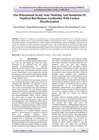
- 5. International Journal of Modern Research in Engineering and Technology (IJMRET) www.ijmret.org Volume 1 Issue 1 ǁ June 2016. w w w . i j m r e t . o r g Page 5 Fig. 2 Experimental setup Figure3 shows the comparison of axial temperature distribution of gasifier obtained from experiment and model. Fig. 3 Comparison of axial temperature distribution of gasifier The temperature is decreasing continuously along the gasifier height. The temperature drop is found to be 130 o C. From Fig. 3 it is clear that there is slight deviation in temperature distribution obtained from model and experiment. This is due to the assumptions made while modeling and due to heat loses in experiment. 0 0.2 0.4 0.6 0.8 1 1.2 500 600 700 800 GasifierHeight(m) Temperature(oC) Code Experimental
- 6. International Journal of Modern Research in Engineering and Technology (IJMRET) www.ijmret.org Volume 1 Issue 1 ǁ June 2016. w w w . i j m r e t . o r g Page 6 3. Results and discussion Fig. 4 Axial mole fraction variation Axial variation of mole fractions of H2, CO2, CO, N2 and CH4 are shown in Fig. 4.It is observed that the fractions of hydrogen and carbon monoxide are increasing and that of carbon dioxide, nitrogen and methane are continuously decreasing. Being an inert gas amount of nitrogen is not changing. But its mole fraction is decreasing due to the net increase in total number of moles of the gas mixture. The decreasing trend of CO2 mole fraction is due to its conversion to CO according to Boudouard reaction whereas increase in H2 concentration is attributed to water gas reaction. Pressure drop across gasifier is found to be 2155 Pa which is matching with the calculated pressure drop, using the relation given by Basu (2006). Pressure drop through bed (theoretical), ∆𝑃𝑏 = 𝜌 𝑝 1 − 𝜀 𝐻𝑔 = 𝜌 𝑝 (1 − 𝜀 𝑚𝑓 )𝐻 𝑚𝑓 𝑔 = 2133.20 Pa Experimentsare conducted with and without CaO at atemperature of 923 K, equivalence ratio of 0.2 and sorbent to biomass ratio of 1.The mole fraction of syngas constituents obtained is shown in Fig. 5. Fig. 5 Effect of sorbent With the use of CaO hydrogen yield is increased. This increase can be justified using Le-Chatelier’s principle, a reaction would proceed in forward direction if the product partial pressure is lower than the reactant partial pressure. Instantaneous removal of CaO will reduce its partial pressure and the resulted forward direction favoured water gas shift reaction will contribute higher hydrogen yield. CaO(s) + CO2 (g) → CaCO3 (s) Another reason for increase in hydrogen 0 0.2 0.4 0.6 0.8 1 1.2 0 0.1 0.2 0.3 0.4 0.5 GasifierHeight(m) Mole fraction CO2 CO CH4 H2 N2 0 5 10 15 20 25 H2 CO CO2 CH4 Molefraction(%) WithoutCaO With CaO
- 7. International Journal of Modern Research in Engineering and Technology (IJMRET) www.ijmret.org Volume 1 Issue 1 ǁ June 2016. w w w . i j m r e t . o r g Page 7 composition is due to the tar cracking. Heat is released inside the gasifier (Acharya et al., 2010)due to exothermic calcination reaction. This will increase the temperature of surrounding producer gas and result in the conversion of more tar to gas which will ultimately leadto an increase in hydrogen yield. IV. Conclusion A steady state one dimensional model for fluidized bed gasifier using CO2 sorbent is developed using MATLAB software. Variation of temperature, pressure, hydrogen, carbon monoxide, carbon dioxide, nitrogen and methane is determined along the gasifier height.Experiments were carried out in a lab scale fluidized bed biomass gasifier and the results were used to validate the model. The proposed model serves as a useful tool for the preliminary performance prediction of fluidized bed reactors. A percentage increase of 50.35 in H2 mole fraction and a similardecrease of 50.88 percentage in CO2 is obtained when CaO is used as sorbent. Ethical responsibility statement The manuscript submitting here has not been submitted/ published previously (partly or in full) to any journal and no data for the preparation of this paper have been fabricated or manipulated. The text and theories of the paper are generated by the authors themselves and all the contributions from other researchers in the theory making are properly acknowledged by including in the paper reference. The authors whose names appear on the submission have contributed sufficiently to the scientific work and therefore share collective responsibility and accountability for the results. In addition to these, consent to submit this paper has been received explicitly from the responsible authorities of our parent institution, National Institute of Technology Calicut. Acknowledgment Authors gratefully acknowledge the financial support provided by MNRE through R&D project on ‘Investigation on bio-hydrogen production by thermo-chemical method in fluidized bed gasifier under catalytic support and its utilization’ (No. 103/181/2010-NT). References [1] Acharya B, Dutta A, Basu P (2010) An investigation into steam gasification of biomass for hydrogen enriched gas production in presence of CaO. International Journal of Hydrogen Energy 35: 1582–1589. doi:10.1016/j.ijhydene.2009.11.109 [2] Babu BV, Sheth PN (2006)Modeling and simulation of reduction zone of downdraft biomass gasifier: Effect of char reactivity factor. Energy Conversion and Management 47: 2602– 2611.doi:10.1016/j.enconman.2005.10.032 [3] Baruah D, Baruah DC (2014) Modeling of biomass gasification: A review. Renewable and Sustainable Energy Reviews 39: 806- 815.doi:10.1016/j.rser.2014.07.129 [4] Basu P (2006) Combustion and Gasification in Fluidized bed. Pergamon press, New York. [5] Basu P (2010) Gasification and Pyrolysis - Practical Design and Theory. Academic press, U K. [6] Bridgwater AV, Renewable fuels and chemicals by thermal processing of biomass. Chemical Engineering Journal 91: 87–102. doi:10.1016/S1385-8947(02)00142-0 [7] Giltrap DL,McKibbin R,Barnes GRG (2003) A steady state model of gas-char reactions in a downdraft biomass gasifier. Solar Energy 74:85–91. doi:10.1016/S0038- 092X(03)00091-4 [8] Inayat A, Ahmad MM, Yusup S, Mutalib MIA (2010) Biomass Steam Gasification with In-Situ CO2 Capture for Enriched Hydrogen Gas Production: A Reaction Kinetics Modelling Approach. Energies 3: 1472-1484.doi:10.3390/en3081472 [9] Inayat A, Ahmad MM, Yusup S, Mutalib MIA (2012)Process modeling for parametric study on oil palm empty fruit bunch steam gasification for hydrogen production. Fuel Processing Technology 93:26– 34.doi:10.1016/j.fuproc.2011.08.014 [10] Maugeri, Leonardo (2006). The Age of Oil: The Mythology, History, and Future of the World's Most Controversial Resource. Lyons Press, USA. [11] McKendry P (2002) Energy production from biomass (part 1): overview of biomass. Bioresource Technology 83: 37-46. doi:10.1016/S0960-8524(01)00118-3 [12] McKendry P (2002) Energy production from biomass (part 3): gasification technologies. Bioresource Technology 83: 55-63. doi:10.1016/S0960-8524(01)00120-1 [13] Ni M, Leung DYC, Leung M KH, Sumathy K (2006) An overview of hydrogen production from biomass. Fuel Processing Technology 87: 461-472.doi:10.1016/j.fuproc.2005.11.0033 [14] Ojus Mohan, Rupesh S, Muraleedharan C, Arun P (2015) Design of Fluidized Bed Reactor for Conversion of Biomass Energy in to Concentrated Gaseous Fuel. IEEE International Conference on Signal Processing, Informatics, Communication and Energy Systems, IEEE Xplore, pp. 1- 5.doi:10.1109/SPICES.2015.7091422 [15] Puig-Arnavat M, Bruno J Coronas A (2010) Review and analysis of biomass gasification models. Renewable and Sustainable Energy
- 8. International Journal of Modern Research in Engineering and Technology (IJMRET) www.ijmret.org Volume 1 Issue 1 ǁ June 2016. w w w . i j m r e t . o r g Page 8 Reviews 14: 2841-285. doi:10.1016/j.rser.2010.07.030 [16] Roy PC, Datta A, ChakrabortyN (2009) Modelling of a downdraft biomass gasifier with finite rate kinetics in the reduction zone. International Journal of Energy Research 33:833–51. doi: 10.1002/er.1517 [17] SaravanakumarA, Hagge MJ, Haridasan TM, Bryden KM (2011) Numerical modeling of a fixed bedupdraft longstick wood gasifier. Biomass and Bioenergy 35:4248–6 doi:10.1016/j.biombioe.2011.07.012 [18] Sharma AK (2008) Equilibrium and kinetic modelling of char reduction reactions in a downdraft biomass gasifier: a comparison. Solar Energy 52:918–28. doi:10.1016/j.solener.2008.03.004 [19] TrommerD, Steinfeld A (2006) Gasification of Petroleum Coke and Experimental Determination ofthe Rate Constants by Dynamic Thermogravimetry in the 500- 1520K Range.Energy& Fuels 20:1250–1258. doi:10.1021/ef050290a [20] Wang Y, Kinoshita CM (1993) Kinetic model of biomass gasification. Solar Energy 51:19– 25. doi:10.1016/0038-092X(93)90037-O Xu Q, Pang S, Levi T (2011) Reaction kinetics and producer gas compositions of steam gasification of coal and biomass blend chars, part 2: mathematicalmodeling and model validation.Chemical Engineering Science 66:2232–40. doi:10.1016/j.ces.2011.02.054